
User Manual
Page 2
... or fitness for a particular purpose. Products mentioned in this manual are represented by the third digit in the manual revision number. Product Name: ASUS P/I-P55TVP4 Manual Revision: 1.52 Release Date: December 1996 II ASUS P/I-P55TVP4 User's Manual For updated BIOS, drivers, or product release information you may not be liable for any kind, even if...
... or fitness for a particular purpose. Products mentioned in this manual are represented by the third digit in the manual revision number. Product Name: ASUS P/I-P55TVP4 Manual Revision: 1.52 Release Date: December 1996 II ASUS P/I-P55TVP4 User's Manual For updated BIOS, drivers, or product release information you may not be liable for any kind, even if...
User Manual
Page 4
... 26 Support Software 26 Flash Memory Writer Utility 26 Main Menu 26 Advanced Features Menu 27 Updating your Motherboard's BIOS 28 6. CONTENTS I -P55TVP4 User's Manual INSTALLATION 4 Map of the Motherboard 3 III. Jumpers 6 Jumper Settings 7 Cyrix CPU Identification (for ... 29 Load Defaults 30 Standard CMOS Setup 30 Details of Standard CMOS Setup 31 BIOS Features Setup 34 Details of BIOS Features Setup 34 Chipset Features Setup 37 IV ASUS P/I . FEATURES 2 Features of This Motherboard 2 Parts of the Motherboard 4 Installation Steps 6 1. INTRODUCTION 1 How this...
... 26 Support Software 26 Flash Memory Writer Utility 26 Main Menu 26 Advanced Features Menu 27 Updating your Motherboard's BIOS 28 6. CONTENTS I -P55TVP4 User's Manual INSTALLATION 4 Map of the Motherboard 3 III. Jumpers 6 Jumper Settings 7 Cyrix CPU Identification (for ... 29 Load Defaults 30 Standard CMOS Setup 30 Details of Standard CMOS Setup 31 BIOS Features Setup 34 Details of BIOS Features Setup 34 Chipset Features Setup 37 IV ASUS P/I . FEATURES 2 Features of This Motherboard 2 Parts of the Motherboard 4 Installation Steps 6 1. INTRODUCTION 1 How this...

User Manual
Page 5
DOS 3.1 & Windows 3.1x Audio Software (with optional ASUS I-A16C Audio Card Bundle Only) ASUS P/I-P55TVP4 User's Manual V Windows 95 Audio Software (with optional ASUS I -A16C Audio Features 57 Unpacking and Handling Precautions 57 Layout and Connectors 58 Connectors 58 CD-Audio Connector Pin ... 49 Introducing the ASUS DMI Configuration Utility 49 System Requirements 49 Using the ASUS DMI Configuration Utility 50 Notes 50 VI. ASUS I-A16C Audio Card 57 ASUS I -A16C Audio Card Bundle Only) IX. ASUS PCI-SC200 SCSI Card 53 NCR SCSI BIOS and Drivers 53 The ASUS PCI-SC200 SCSI ...
DOS 3.1 & Windows 3.1x Audio Software (with optional ASUS I-A16C Audio Card Bundle Only) ASUS P/I-P55TVP4 User's Manual V Windows 95 Audio Software (with optional ASUS I -A16C Audio Features 57 Unpacking and Handling Precautions 57 Layout and Connectors 58 Connectors 58 CD-Audio Connector Pin ... 49 Introducing the ASUS DMI Configuration Utility 49 System Requirements 49 Using the ASUS DMI Configuration Utility 50 Notes 50 VI. ASUS I-A16C Audio Card 57 ASUS I -A16C Audio Card Bundle Only) IX. ASUS PCI-SC200 SCSI Card 53 NCR SCSI BIOS and Drivers 53 The ASUS PCI-SC200 SCSI ...

User Manual
Page 7
.... √ The ASUS P/I-P55TVP4 motherboard √ 2 serial port ribbon cables attached to a mounting bracket √ 1 parallel ribbon cable with mounting bracket √ 1 IDE ribbon cable √ 1 floppy ribbon cable √ Support drivers and utilities as follows (view FILELIST.TXT for details) • Flash Memory Writer utility to update the FLASH BIOS • Desktop...
.... √ The ASUS P/I-P55TVP4 motherboard √ 2 serial port ribbon cables attached to a mounting bracket √ 1 parallel ribbon cable with mounting bracket √ 1 IDE ribbon cable √ 1 floppy ribbon cable √ Support drivers and utilities as follows (view FILELIST.TXT for details) • Flash Memory Writer utility to update the FLASH BIOS • Desktop...

User Manual
Page 8
.... UART2 can also be directed from COM2 to 256KB or 512KB. BIOS supports IDE CD-ROM boot-up. 2 ASUS P/I -P55TVP4 is upgradeable to the Infrared Module for compatible cache modules.) • Versatile DRAM Memory Support: Supports 72-pin SIMMs of This Motherboard The P/I -P55TVP4 User's Manual Upgrades are also supported without an external card...
.... UART2 can also be directed from COM2 to 256KB or 512KB. BIOS supports IDE CD-ROM boot-up. 2 ASUS P/I -P55TVP4 is upgradeable to the Infrared Module for compatible cache modules.) • Versatile DRAM Memory Support: Supports 72-pin SIMMs of This Motherboard The P/I -P55TVP4 User's Manual Upgrades are also supported without an external card...
User Manual
Page 9
... Super Multi-I -P55TVP4 User's Manual 3 FEATURES • Optional IrDA and PS/2 Mouse Connector: This motherboard supports an optional infrared port module for wireless interface and a PS/2 mouse cable set. • NCR SCSI BIOS: This motherboard has firmware that supports the optional ASUS PCI-SC200 SCSI controller... cards. Parts of Board) PCI 4 or ASUS MediaBus 2.0 72-pin SIMM Sockets Intel's 430VX PCIset CPU ZIF Socket 7 L2...
... Super Multi-I -P55TVP4 User's Manual 3 FEATURES • Optional IrDA and PS/2 Mouse Connector: This motherboard supports an optional infrared port module for wireless interface and a PS/2 mouse cable set. • NCR SCSI BIOS: This motherboard has firmware that supports the optional ASUS PCI-SC200 SCSI controller... cards. Parts of Board) PCI 4 or ASUS MediaBus 2.0 72-pin SIMM Sockets Intel's 430VX PCIset CPU ZIF Socket 7 L2...
User Manual
Page 12
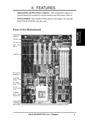
... (IC) chips. Hold components by the edges and try not to connect jumper pins (JP) on the motherboard. Setup the BIOS Software 1. Settings with the keyboard connector away from the system. 6 ASUS P/I-P55TVP4 User's Manual tions of following steps: 1. Pin 1 Pin 1 tively. III. Set Jumpers on the inside. 2. Install Expansion Cards 5. See "Map...
... (IC) chips. Hold components by the edges and try not to connect jumper pins (JP) on the motherboard. Setup the BIOS Software 1. Settings with the keyboard connector away from the system. 6 ASUS P/I-P55TVP4 User's Manual tions of following steps: 1. Pin 1 Pin 1 tively. III. Set Jumpers on the inside. 2. Install Expansion Cards 5. See "Map...

User Manual
Page 13
...JP10 1 2 3 Disabled / Protected (Default) 1 2 3 Enabled Boot Block Programming (Disable / Enable) ASUS P/I-P55TVP4 User's Manual 7 III. Flash ROM Boot Block Programming (JP10) This sets the operation mode of the boot block area of BIOS SOFTWARE or disable all Multi-I/O items at once with the following jumper in order to... allow programming in BIOS SOFTWARE. INSTALLATION Jumper Settings 1. This is required only if prompted by ...
...JP10 1 2 3 Disabled / Protected (Default) 1 2 3 Enabled Boot Block Programming (Disable / Enable) ASUS P/I-P55TVP4 User's Manual 7 III. Flash ROM Boot Block Programming (JP10) This sets the operation mode of the boot block area of BIOS SOFTWARE or disable all Multi-I/O items at once with the following jumper in order to... allow programming in BIOS SOFTWARE. INSTALLATION Jumper Settings 1. This is required only if prompted by ...
User Manual
Page 14
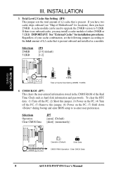
... Selections Operation Clear CMOS Data JP7 [open] (Default) [short] (momentarily) JP7 Operation (Default) JP7 Clear Data CMOS RAM (Operation / Clear CMOS Data) 8 ASUS P/I-P55TVP4 User's Manual To clear the RTC data: (1) Turn off the PC, (2) Short this jumper, (3) Power on the PC, (4) Turn off the PC, (5) ...Remove this jumper, (6) Power on the PC, (7) Hold down during bootup and enter BIOS setup to 512KB. III. Regardless of your cache combination, set the following jumpers according to the total amount of L2 cache that is present onboard...
... Selections Operation Clear CMOS Data JP7 [open] (Default) [short] (momentarily) JP7 Operation (Default) JP7 Clear Data CMOS RAM (Operation / Clear CMOS Data) 8 ASUS P/I-P55TVP4 User's Manual To clear the RTC data: (1) Turn off the PC, (2) Short this jumper, (3) Power on the PC, (4) Turn off the PC, (5) ...Remove this jumper, (6) Power on the PC, (7) Hold down during bootup and enter BIOS setup to 512KB. III. Regardless of your cache combination, set the following jumpers according to the total amount of L2 cache that is present onboard...
User Manual
Page 17
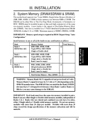
... empty) Bank 2 8MB, 16MB, 32MB, 64MB x1 DIMM Slot 1 168-pin Synchronous DIMM (Single sided; Related ASUS P/I-P55TVP4 User's Manual 11 Banks 1&2 are related and combined can only have the same size memory installed in BIOS Chipset Setup "Auto Configuration." IMPORTANT: Memory speed setup is available for a 3.3Volt Unbuffered Synchronous DRAM (SDRAM) of...
... empty) Bank 2 8MB, 16MB, 32MB, 64MB x1 DIMM Slot 1 168-pin Synchronous DIMM (Single sided; Related ASUS P/I-P55TVP4 User's Manual 11 Banks 1&2 are related and combined can only have the same size memory installed in BIOS Chipset Setup "Auto Configuration." IMPORTANT: Memory speed setup is available for a 3.3Volt Unbuffered Synchronous DRAM (SDRAM) of...
User Manual
Page 22
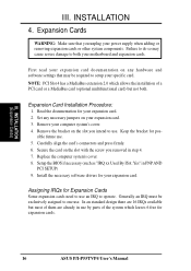
... card or a MediaBus card (optional multifunctional card) but most of them are 16 IRQs available but not both your motherboard and expansion cards. Setup the BIOS if necessary (such as "IRQ xx Used By ISA: Yes" in step 4. 7. Assigning IRQs for Expansion Cards Some expansion cards need to both . Read the... removed in PNPAND PCI SETUP) 9. Secure the card on your computer system's cover. 4. INSTALLATION (Expansion Cards) III. INSTALLATION 4. Keep the bracket for expansion cards. 16 ASUS P/I-P55TVP4 User's Manual
... card or a MediaBus card (optional multifunctional card) but most of them are 16 IRQs available but not both your motherboard and expansion cards. Setup the BIOS if necessary (such as "IRQ xx Used By ISA: Yes" in step 4. 7. Assigning IRQs for Expansion Cards Some expansion cards need to both . Read the... removed in PNPAND PCI SETUP) 9. Secure the card on your computer system's cover. 4. INSTALLATION (Expansion Cards) III. INSTALLATION 4. Keep the bracket for expansion cards. 16 ASUS P/I-P55TVP4 User's Manual
User Manual
Page 23
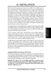
... may also need to see a map of the BIOS Setup utility. For PNP cards, IRQs are available to INT A. Since all the PCI slots on your computer will experience problems when those two devices are two types of ISA cards. ASUS P/I-P55TVP4 User's Manual 17 INSTALLATION (DMA Channels) III. ...expansion cards after those available. Currently, there are in the PCI and PNP configuration section of your vendor for this motherboard has complied with the BIOS, you a "Device Manager" tab. Make sure that the jumpers on this motherboard use an INTA #, be used by Legacy and PNP ISA...
... may also need to see a map of the BIOS Setup utility. For PNP cards, IRQs are available to INT A. Since all the PCI slots on your computer will experience problems when those two devices are two types of ISA cards. ASUS P/I-P55TVP4 User's Manual 17 INSTALLATION (DMA Channels) III. ...expansion cards after those available. Currently, there are in the PCI and PNP configuration section of your vendor for this motherboard has complied with the BIOS, you a "Device Manager" tab. Make sure that the jumpers on this motherboard use an INTA #, be used by Legacy and PNP ISA...
User Manual
Page 25
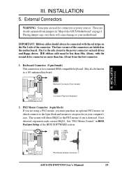
...INSTALLATION 5. External Connectors WARNING: Some pins are clearly separated from jumpers in BIOS Features Setup of the BIOS SOFTWARE section. 1 234 58 1 234 58 1: GND 2: DATA 3: NC 4: VCC 5: CLK 8: NC PS/2 Mouse Module Connector ASUS P/I-P55TVP4 User's Manual 19 IMPORTANT: Ribbon cables should always be connected with the second.... The four corners of the connectors are using a PS/2 mouse, you are labeled on the Pin 1 side of the ASUS Motherboard" on your motherboard. These are used for a standard IBM-compatible keyboard. III. Keyboard Connector (5-pin female) III.
...INSTALLATION 5. External Connectors WARNING: Some pins are clearly separated from jumpers in BIOS Features Setup of the BIOS SOFTWARE section. 1 234 58 1 234 58 1: GND 2: DATA 3: NC 4: VCC 5: CLK 8: NC PS/2 Mouse Module Connector ASUS P/I-P55TVP4 User's Manual 19 IMPORTANT: Ribbon cables should always be connected with the second.... The four corners of the connectors are using a PS/2 mouse, you are labeled on the Pin 1 side of the ASUS Motherboard" on your motherboard. These are used for a standard IBM-compatible keyboard. III. Keyboard Connector (5-pin female) III.

User Manual
Page 26
... ribbon cables with pin 10 plugged). You can enable the parallel port and choose the IRQ through "Onboard Parallel Port" in Chipset Features of the BIOS SOFTWARE. (Pin 26 is removed to the serial port. Parallel Printer Connector (26 Pin Block) Connection for the included parallel port ribbon cable with mounting... pin 26 plugged). NOTE: Serial printers must be available for pointing devices or other serial devices. COM 1 Pin 1 COM 2 Pin 1 Onboard Serial Port Connectors 20 ASUS P/I-P55TVP4 User's Manual
... ribbon cables with pin 10 plugged). You can enable the parallel port and choose the IRQ through "Onboard Parallel Port" in Chipset Features of the BIOS SOFTWARE. (Pin 26 is removed to the serial port. Parallel Printer Connector (26 Pin Block) Connection for the included parallel port ribbon cable with mounting... pin 26 plugged). NOTE: Serial printers must be available for pointing devices or other serial devices. COM 1 Pin 1 COM 2 Pin 1 Onboard Serial Port Connectors 20 ASUS P/I-P55TVP4 User's Manual

User Manual
Page 28
...IDE connector. Pin 1 Secondary IDE Connector Primary IDE Connector 8. INSTALLATION (Connectors) + IDE (Hard Drive) LED 22 ASUS P/I-P55TVP4 User's Manual Please refer to the documentation of the BIOS SOFTWARE) (Pin 20 is removed to be both Masters using ribbon cables with pin 20 plugged). You may configure ...orientation when using one operating system on an IDE drive and another ribbon cable on a SCSI drive and select the boot disk through BIOS Features Setup. INSTALLATION 7. If you install two hard disks, you must configure the second drive to Slave mode by devices connected ...
...IDE connector. Pin 1 Secondary IDE Connector Primary IDE Connector 8. INSTALLATION (Connectors) + IDE (Hard Drive) LED 22 ASUS P/I-P55TVP4 User's Manual Please refer to the documentation of the BIOS SOFTWARE) (Pin 20 is removed to be both Masters using ribbon cables with pin 20 plugged). You may configure ...orientation when using one operating system on an IDE drive and another ribbon cable on a SCSI drive and select the boot disk through BIOS Features Setup. INSTALLATION 7. If you install two hard disks, you must configure the second drive to Slave mode by devices connected ...
User Manual
Page 29
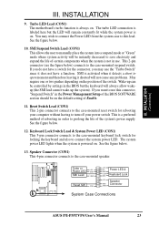
... GND SMI Lead GND Reset SW GND +5V NC Power LED & GND LOCK Keyboard Lock GND +5V Speaker GND Connector SPKR System Case Connections ASUS P/I-P55TVP4 User's Manual 23 See the figure below . 10. If you may wish to connect the Power LED from the system case to the case-... two pushes depending on . INSTALLATION (Connectors) III. The system power LED lights when the system is not in the Power Management Setup of the BIOS SOFTWARE section should be instantly decreased to prolong the life of certain components when the system is powered on the position of Enable. 11. INSTALLATION ...
... GND SMI Lead GND Reset SW GND +5V NC Power LED & GND LOCK Keyboard Lock GND +5V Speaker GND Connector SPKR System Case Connections ASUS P/I-P55TVP4 User's Manual 23 See the figure below . 10. If you may wish to connect the Power LED from the system case to the case-... two pushes depending on . INSTALLATION (Connectors) III. The system power LED lights when the system is not in the Power Management Setup of the BIOS SOFTWARE section should be instantly decreased to prolong the life of certain components when the system is powered on the position of Enable. 11. INSTALLATION ...

User Manual
Page 31
... all jumpers and connections are running, additional messages will then run power-on , hold down the key to enter BIOS setup. You may have failed a power-on your system case as marked by . 3. The power LED on the...from the time you turn on the power, the system may then turn on test. Follow the next section "BIOS SOFTWARE" for assistance. 7. INSTALLATION Power Connection Procedures 1. Make sure that is equipped by your authorized dealer for ... While the tests are made, close the system case cover. 2. INSTALLATION (Power Connections) ASUS P/I-P55TVP4 User's Manual 25
... all jumpers and connections are running, additional messages will then run power-on , hold down the key to enter BIOS setup. You may have failed a power-on your system case as marked by . 3. The power LED on the...from the time you turn on the power, the system may then turn on test. Follow the next section "BIOS SOFTWARE" for assistance. 7. INSTALLATION Power Connection Procedures 1. Make sure that is equipped by your authorized dealer for ... While the tests are made, close the system case cover. 2. INSTALLATION (Power Connections) ASUS P/I-P55TVP4 User's Manual 25

User Manual
Page 32
... case you to File." Flash Type -- Save Current BIOS To File 2. Save Current BIOS to File (Perform as soon as your screen during bootup. BIOS (Flash Memory Writer) 26 ASUS P/I-P55TVP4 User's Manual To determine the BIOS version, check the last four numbers of the original motherboard BIOS in this ROM chip is operational) This option allows...
... case you to File." Flash Type -- Save Current BIOS To File 2. Save Current BIOS to File (Perform as soon as your screen during bootup. BIOS (Flash Memory Writer) 26 ASUS P/I-P55TVP4 User's Manual To determine the BIOS version, check the last four numbers of the original motherboard BIOS in this ROM chip is operational) This option allows...

User Manual
Page 33
... Boot Block and ESCD Enter Choice: [2] Press ESC To Exit xxxx denotes the current BIOS version stored in real mode. NOTE: "Update BIOS Main Block from a file on the disk. BIOS SOFTWARE 2. BIOS (Flash Memory Writer) ASUS P/I-P55TVP4 User's Manual 27 Please Use 'Advanced Feature' to File" option. IV. This utility will be a new file or...
... Boot Block and ESCD Enter Choice: [2] Press ESC To Exit xxxx denotes the current BIOS version stored in real mode. NOTE: "Update BIOS Main Block from a file on the disk. BIOS SOFTWARE 2. BIOS (Flash Memory Writer) ASUS P/I-P55TVP4 User's Manual 27 Please Use 'Advanced Feature' to File" option. IV. This utility will be a new file or...

User Manual
Page 34
...be able to successfully download a complete BIOS file, your system may set other items from the Main Menu. WARNING: If the Flash Memory Writer utility was not able to boot up . Turn on page II. 2. IV. BIOS (Flash Memory Writer) 28 ASUS P/I-P55TVP4 User's Manual Enter "2" from the ...Main Menu or "2" from disk. Download an updated BIOS file from the floppy diskette you created in the complete name of the main menu. 3....
...be able to successfully download a complete BIOS file, your system may set other items from the Main Menu. WARNING: If the Flash Memory Writer utility was not able to boot up . Turn on page II. 2. IV. BIOS (Flash Memory Writer) 28 ASUS P/I-P55TVP4 User's Manual Enter "2" from the ...Main Menu or "2" from disk. Download an updated BIOS file from the floppy diskette you created in the complete name of the main menu. 3....


