
User Manual
Page 4
...System Memory (DRAM & SRAM 14 DRAM Installation Procedures 15 Static RAM (SRAM) for Level 2 (External) Cache 16 Compatible Cache Modules for ISA Cards 19 ASUS MediaBus Card 20 5. BIOS SOFTWARE 28 6. BIOS Setup 28 Standard CMOS Setup 29 Details of the Motherboard 4 Jumpers 5 Expansion Slots 5 Connectors 5 Installation Steps 6 1. INSTALLATION 4 Map of Standard CMOS Setup 30 IV P/E-P55T2P4D User's Manual External Connectors 21 Power Connection Procedures 27 IV. FEATURES 2 Features of This Motherboard 2 Parts of the Motherboard 3 III. Central Processing Unit (CPU...
...System Memory (DRAM & SRAM 14 DRAM Installation Procedures 15 Static RAM (SRAM) for Level 2 (External) Cache 16 Compatible Cache Modules for ISA Cards 19 ASUS MediaBus Card 20 5. BIOS SOFTWARE 28 6. BIOS Setup 28 Standard CMOS Setup 29 Details of the Motherboard 4 Jumpers 5 Expansion Slots 5 Connectors 5 Installation Steps 6 1. INSTALLATION 4 Map of Standard CMOS Setup 30 IV P/E-P55T2P4D User's Manual External Connectors 21 Power Connection Procedures 27 IV. FEATURES 2 Features of This Motherboard 2 Parts of the Motherboard 3 III. Central Processing Unit (CPU...

User Manual
Page 7
...) I . Installation: Instructions on use of an optional SCSI card Item Checklist Please check that your retailer. √ The P/E-P55T2P4D motherboard √ 2 serial port ribbon cables attached to a mounting bracket √ 1 parallel ribbon cable with mounting bracket √ 1 IDE ribbon cable √ 1 floppy ribbon cable √ 1 diskette containing support software as follows: • Flash Memory Writer utility to update motherboard BIOS • Binary file containing a BIOS version • Desktop Management Interface (DMI) software • System Configuration Utility (SCU...
...) I . Installation: Instructions on use of an optional SCSI card Item Checklist Please check that your retailer. √ The P/E-P55T2P4D motherboard √ 2 serial port ribbon cables attached to a mounting bracket √ 1 parallel ribbon cable with mounting bracket √ 1 IDE ribbon cable √ 1 floppy ribbon cable √ 1 diskette containing support software as follows: • Flash Memory Writer utility to update motherboard BIOS • Binary file containing a BIOS version • Desktop Management Interface (DMI) software • System Configuration Utility (SCU...

User Manual
Page 9
... controller supports PIO Modes 3 & 4 and Bus Master IDE DMA Mode 2. BIOS supports IDE CD-ROM drive bootup. • Optional IrDA and PS/2 Mouse Connector: This motherboard supports an optional infrared port module for wireless interface and a PS/2 mouse cable set for connecting a PS/2 mouse. FEATURES (Parts of the Motherboard 4 EISA Slots 3 PCI Slots Onboard IDE, Floppy, Serial 2 CPU ZIF Socket 7 L2 Cache Expansion Slot 1 ISA Slot PCI 4 or ASUS MediaBus 2.0 Super Multi-I/O Intel's 430HX PCIset (8) 72-pin SIMM Sockets Self-Powered RealTime Clock Programmable Flash ROM P/E-P55T2P4D User...
... controller supports PIO Modes 3 & 4 and Bus Master IDE DMA Mode 2. BIOS supports IDE CD-ROM drive bootup. • Optional IrDA and PS/2 Mouse Connector: This motherboard supports an optional infrared port module for wireless interface and a PS/2 mouse cable set for connecting a PS/2 mouse. FEATURES (Parts of the Motherboard 4 EISA Slots 3 PCI Slots Onboard IDE, Floppy, Serial 2 CPU ZIF Socket 7 L2 Cache Expansion Slot 1 ISA Slot PCI 4 or ASUS MediaBus 2.0 Super Multi-I/O Intel's 430HX PCIset (8) 72-pin SIMM Sockets Self-Powered RealTime Clock Programmable Flash ROM P/E-P55T2P4D User...
User Manual
Page 11
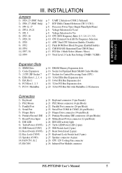
... connector (6-pin Block) p. 22 Parallel Port connector (26-pin Block) p. 22 Serial Port COM1 & COM2 (10-pin Blocks) p. 23 Floppy Drive connector (34-pin Block) p. 23 Primary/Secondary IDE connectors (40-pin Blocks) p. 24 Motherboard Power connector (12-pin Block) p. 24 IDE LED activity light p. 25 Turbo LED/Power LED (2-pins) p. 25 SMI Switch lead (2-pins) p. 25 Reset Switch lead (2-pins) p. 25 Keyboard Lock Switch lead (5-pins) p. 25 Speaker connector (4-pins) p. 26 CPU 12V Cooling Fan connector p. 26 Infrared Port Module connector P/E-P55T2P4D User's Manual 5 III. INSTALLATION Jumpers...
... connector (6-pin Block) p. 22 Parallel Port connector (26-pin Block) p. 22 Serial Port COM1 & COM2 (10-pin Blocks) p. 23 Floppy Drive connector (34-pin Block) p. 23 Primary/Secondary IDE connectors (40-pin Blocks) p. 24 Motherboard Power connector (12-pin Block) p. 24 IDE LED activity light p. 25 Turbo LED/Power LED (2-pins) p. 25 SMI Switch lead (2-pins) p. 25 Reset Switch lead (2-pins) p. 25 Keyboard Lock Switch lead (5-pins) p. 25 Speaker connector (4-pins) p. 26 CPU 12V Cooling Fan connector p. 26 Infrared Port Module connector P/E-P55T2P4D User's Manual 5 III. INSTALLATION Jumpers...
User Manual
Page 12
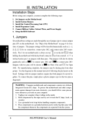
... Circuit (IC) chips. INSTALLATION (Jumpers) III. Install the Central Processing Unit (CPU) 4. The jumper settings will be described numerically such as for Short (On) and for our motherboards is written besides pin 1 on the left when holding the motherboard with three pins. Use the diagrams in this manual instead of the Motherboard" on the board. Use a grounded wrist strap before handling computer components. 4. Connect Ribbon Cables, Cabinet Wires, and Power Supply 6. See "Map...
... Circuit (IC) chips. INSTALLATION (Jumpers) III. Install the Central Processing Unit (CPU) 4. The jumper settings will be described numerically such as for Short (On) and for our motherboards is written besides pin 1 on the left when holding the motherboard with three pins. Use the diagrams in this manual instead of the Motherboard" on the board. Use a grounded wrist strap before handling computer components. 4. Connect Ribbon Cables, Cabinet Wires, and Power Supply 6. See "Map...

User Manual
Page 26
... above Audio features Creative Technology, Ltd. * All the above Video features ATI, Inc. (AV868 Video features S3, Inc.) * All the above SCSI features Adaptec, Inc. 20 P/E-P55T2P4D User's Manual The add-on this motherboard. The difference between the MediaBus extension and the PCI Slot 4 has been increased from being installed into the shared PCI 4 / MediaBus 2.0 Slot. NOTE: This motherboard uses MediaBus Rev. 2.0. INSTALLATION (Connectors) III. INSTALLATION ASUS MediaBus Card MediaBus...
... above Audio features Creative Technology, Ltd. * All the above Video features ATI, Inc. (AV868 Video features S3, Inc.) * All the above SCSI features Adaptec, Inc. 20 P/E-P55T2P4D User's Manual The add-on this motherboard. The difference between the MediaBus extension and the PCI Slot 4 has been increased from being installed into the shared PCI 4 / MediaBus 2.0 Slot. NOTE: This motherboard uses MediaBus Rev. 2.0. INSTALLATION (Connectors) III. INSTALLATION ASUS MediaBus Card MediaBus...

User Manual
Page 31
... the system power is on the position of Section IV). 11. SMI suspend switch lead (CON3) This allows the user to turn off your power switch This is not in the BIOS but the LED will be controlled by settings in use this lead. Speaker connector (CON3) This 4-pin connector connects to the case-mounted suspend switch. See the figure below ) connects to the case-mounted speaker. Wake-up the system). INSTALLATION (Connectors) III...
... the system power is on the position of Section IV). 11. SMI suspend switch lead (CON3) This allows the user to turn off your power switch This is not in the BIOS but the LED will be controlled by settings in use this lead. Speaker connector (CON3) This 4-pin connector connects to the case-mounted suspend switch. See the figure below ) connects to the case-mounted speaker. Wake-up the system). INSTALLATION (Connectors) III...

User Manual
Page 33
... note of these memory chips can also restart by pushing the Reset button on again. IV. Use the Flash Memory Writer utility to enter new setup information. If your system using this program. BIOS (BIOS Setup) 28 P/E-P55T2P4D User's Manual The BIOS ROM of programmable Flash ROM chips: 5 Volt and 12 Volt. You can be updated when BIOS upgrades are a little bit late pressing the mentioned key(s), POST will appear with the opportunity to configure your motherboard came in detail...
... note of these memory chips can also restart by pushing the Reset button on again. IV. Use the Flash Memory Writer utility to enter new setup information. If your system using this program. BIOS (BIOS Setup) 28 P/E-P55T2P4D User's Manual The BIOS ROM of programmable Flash ROM chips: 5 Volt and 12 Volt. You can be updated when BIOS upgrades are a little bit late pressing the mentioned key(s), POST will appear with the opportunity to configure your motherboard came in detail...

User Manual
Page 34
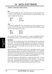
... some basic system hardware configuration and set the system clock and error handling. P/E-P55T2P4D User's Manual 29 Choosing defaults at this option anymore. BIOS SOFTWARE NOTE: The "Load BIOS Defaults" option loads the most conservative settings for regular use on the selected field, press the key. The help menu will not need . BIOS (Standard CMOS) The above screen displays the control keys for use . The memory display at the bottom of these keys and their respective uses. Take note of the...
... some basic system hardware configuration and set the system clock and error handling. P/E-P55T2P4D User's Manual 29 Choosing defaults at this option anymore. BIOS SOFTWARE NOTE: The "Load BIOS Defaults" option loads the most conservative settings for regular use on the selected field, press the key. The help menu will not need . BIOS (Standard CMOS) The above screen displays the control keys for use . The memory display at the bottom of these keys and their respective uses. Take note of the...
User Manual
Page 35
... IDE devices. Specifications for SCSI hard disks need not to be entered here since they operate using device drivers and are : Month: Day: Year: 1 to 12 1 to 31 up to install the required SCSI drivers. To select, simply press the or key to set the time, highlight the "Time" field and then press the page up to the MS-DOS manual. BIOS (Standard CMOS) 30 P/E-P55T2P4D User's Manual keys to change...
... IDE devices. Specifications for SCSI hard disks need not to be entered here since they operate using device drivers and are : Month: Day: Year: 1 to 12 1 to 31 up to install the required SCSI drivers. To select, simply press the or key to set the time, highlight the "Time" field and then press the page up to the MS-DOS manual. BIOS (Standard CMOS) 30 P/E-P55T2P4D User's Manual keys to change...

User Manual
Page 39
... utilize this field is set the two typematic controls listed next. Typematic Rate Setting When enabled, you to Disabled. A,C; Boot Up NumLock Status This field enables users to check first the hard disk and then the floppy drive; that Drive A becomes Drive B, and Drive B becomes Drive A under DOS. The setup default setting for an operating system. Quick Power On Self Test This field speeds up the Power-On Self Test (POST) routine by allowing the setting...
... utilize this field is set the two typematic controls listed next. Typematic Rate Setting When enabled, you to Disabled. A,C; Boot Up NumLock Status This field enables users to check first the hard disk and then the floppy drive; that Drive A becomes Drive B, and Drive B becomes Drive A under DOS. The setup default setting for an operating system. Quick Power On Self Test This field speeds up the Power-On Self Test (POST) routine by allowing the setting...

User Manual
Page 40
... change the video BIOS location from 6 to boot. Shadowing a ROM reduces the memory available between 640KB and 1024KB by using the Supervisor Password or User Password option from the main screen as explained later in this problem. BIOS (BIOS Features) P/E-P55T2P4D User's Manual 35 Setup default setting is Enabled. Four delay rate options are non-standard VGA such as information access is an expansion ROM, the shadow option of its corresponding address should correct this section. The setting Enabled should be Enabled...
... change the video BIOS location from 6 to boot. Shadowing a ROM reduces the memory available between 640KB and 1024KB by using the Supervisor Password or User Password option from the main screen as explained later in this problem. BIOS (BIOS Features) P/E-P55T2P4D User's Manual 35 Setup default setting is Enabled. Four delay rate options are non-standard VGA such as information access is an expansion ROM, the shadow option of its corresponding address should correct this section. The setting Enabled should be Enabled...
User Manual
Page 42
... AB, otherwise leave on DRAM memory modules.) Onboard FDC Controller The default of Enabled allows you want to use a different controller card to connect the floppy drives, set this field to correct 1 bit memory errors that may occur in the memory. (See pages 12-13 for the motherboard's two onboard serial connectors. If you to connect your monitor. This works separately from the default of Parity or ECC (Error Checking and Correcting) to Disabled. BIOS (Chipset Features) P/E-P55T2P4D User's Manual 37 IV.
... AB, otherwise leave on DRAM memory modules.) Onboard FDC Controller The default of Enabled allows you want to use a different controller card to connect the floppy drives, set this field to correct 1 bit memory errors that may occur in the memory. (See pages 12-13 for the motherboard's two onboard serial connectors. If you to connect your monitor. This works separately from the default of Parity or ECC (Error Checking and Correcting) to Disabled. BIOS (Chipset Features) P/E-P55T2P4D User's Manual 37 IV.

User Manual
Page 45
... field is user-configurable to activate the video off . at Min Saving after one hour. Use the latter for this software cannot display. Take note that do not support the "Green" feature. Suspend Switch This field enables or disables the SMI connector on the system case. The first option V/H SYNC + Blank, which each mode. While the monitor is the default setting, blanks the screen and turns off features. HDD Power Down...
... field is user-configurable to activate the video off . at Min Saving after one hour. Use the latter for this software cannot display. Take note that do not support the "Green" feature. Suspend Switch This field enables or disables the SMI connector on the system case. The first option V/H SYNC + Blank, which each mode. While the monitor is the default setting, blanks the screen and turns off features. HDD Power Down...

User Manual
Page 46
... mouse or click its button. Activity detected from suspended mode. PCI Latency Timer The default setting of the system. The power management feature will use IRQ12. All PCI bus slots on the enabled IRQ channels. IRQ3 to this motherboard. The other options are manual settings of the screen. BIOS (Plug & Play / PCI) The first four fields on the screen set IRQs 3 - 15 individually. PNP and PCI Setup This "PNP and PCI Setup" option configures the PCI bus slots. IV. P/E-P55T2P4D User's Manual 41 IV.
... mouse or click its button. Activity detected from suspended mode. PCI Latency Timer The default setting of the system. The power management feature will use IRQ12. All PCI bus slots on the enabled IRQ channels. IRQ3 to this motherboard. The other options are manual settings of the screen. BIOS (Plug & Play / PCI) The first four fields on the screen set IRQs 3 - 15 individually. PNP and PCI Setup This "PNP and PCI Setup" option configures the PCI bus slots. IV. P/E-P55T2P4D User's Manual 41 IV.

User Manual
Page 47
... to Yes. BIOS (Plug & Play / PCI) 42 P/E-P55T2P4D User's Manual If you must set IRQ10 Used By ISA to set the base address and block size of No/ECU. If you install a Legacy EISA/ISA card that requires a unique DMA channel, and you are not using an ECU, you install a Legacy EISA/ISA card that channel. BIOS SOFTWARE IRQ xx Used By ISA These fields indicate whether or not the displayed IRQ for...
... to Yes. BIOS (Plug & Play / PCI) 42 P/E-P55T2P4D User's Manual If you must set IRQ10 Used By ISA to set the base address and block size of No/ECU. If you install a Legacy EISA/ISA card that requires a unique DMA channel, and you are not using an ECU, you install a Legacy EISA/ISA card that channel. BIOS SOFTWARE IRQ xx Used By ISA These fields indicate whether or not the displayed IRQ for...

User Manual
Page 49
... asking you forget the password, see page 12 for the password. By default, the system comes without any passwords. "Supervisor Password" sets a password that will prompt for procedures on the screen. To specify a password, highlight the type you want and then press the key. A message confirms the password has been disabled. IV. BIOS SOFTWARE Supervisor Password and User Password These two options set the system passwords. A password prompt appears on clearing the CMOS. 44 P/E-P55T2P4D User's Manual
... asking you forget the password, see page 12 for the password. By default, the system comes without any passwords. "Supervisor Password" sets a password that will prompt for procedures on the screen. To specify a password, highlight the type you want and then press the key. A message confirms the password has been disabled. IV. BIOS SOFTWARE Supervisor Password and User Password These two options set the system passwords. A password prompt appears on clearing the CMOS. 44 P/E-P55T2P4D User's Manual
User Manual
Page 50
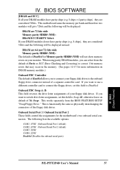
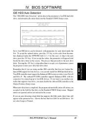
... feature Enhanced IDE support for four devices, you must support the Enhanced IDE features in the screen. To accept the optimal entries, press the key or else select from the numbers displayed under the OPTIONS field (2, 1, 3 in the parameter box. IV. ROM EISA BIOS (PE55TP4D) CMOS SETUP UTILITY AWARD SOFTWARE, INC. When auto-detection is completed, the program automatically enters all entries you accepted on the screen. BIOS (Hard Drive Detect) P/E-P55T2P4D User's Manual 45...
... feature Enhanced IDE support for four devices, you must support the Enhanced IDE features in the screen. To accept the optimal entries, press the key or else select from the numbers displayed under the OPTIONS field (2, 1, 3 in the parameter box. IV. ROM EISA BIOS (PE55TP4D) CMOS SETUP UTILITY AWARD SOFTWARE, INC. When auto-detection is completed, the program automatically enters all entries you accepted on the screen. BIOS (Hard Drive Detect) P/E-P55T2P4D User's Manual 45...

User Manual
Page 51
... on the hard drive. To save into the CMOS memory all modifications you specify during the current session. IMPORTANT: If your drive, do not need to save the configuration changes, highlight the "Save & Exit Setup" option on it. BIOS (Save & Exit) Exit Without Saving Select this option to enter the correct parameters manually or use more than one set . BIOS SOFTWARE The auto-detection feature can use low-level...
... on the hard drive. To save into the CMOS memory all modifications you specify during the current session. IMPORTANT: If your drive, do not need to save the configuration changes, highlight the "Save & Exit Setup" option on it. BIOS (Save & Exit) Exit Without Saving Select this option to enter the correct parameters manually or use more than one set . BIOS SOFTWARE The auto-detection feature can use low-level...
User Manual
Page 54
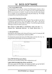
... to copy the contents of the following if advanced features if necessary. Boot Block of the original motherboard BIOS in the \FLASH directory. Please Use 'Advanced Feature' to the DOS prompt, press the key. Update BIOS Including Boot Block and ESCD Enter Choice: [2] Press ESC To Exit Clear PNP ESCD Parameter Block This option erases the Plug-and-Play (PnP) configuration record. BIOS (Flash Memory Writer) P/E-P55T2P4D User's Manual 49
... to copy the contents of the following if advanced features if necessary. Boot Block of the original motherboard BIOS in the \FLASH directory. Please Use 'Advanced Feature' to the DOS prompt, press the key. Update BIOS Including Boot Block and ESCD Enter Choice: [2] Press ESC To Exit Clear PNP ESCD Parameter Block This option erases the Plug-and-Play (PnP) configuration record. BIOS (Flash Memory Writer) P/E-P55T2P4D User's Manual 49


