MEW-AM User Manual
Page 1
R MEW-AM Socket 370 Intel® 810 microATX Motherboard USER'S MANUAL
R MEW-AM Socket 370 Intel® 810 microATX Motherboard USER'S MANUAL

MEW-AM User Manual
Page 4
FEATURES 8 2.1 The ASUS MEW-AM Motherboard 8 2.1.1 Specifications 8 2.1.3 Performance 9 2.2 ASUS MEW-AM Part Definitions 10 2.3 ASUS MEW-AM Part Locations 11 3. HARDWARE SETUP 12 3.1 Motherboard Layout 12 3.3 Hardware Setup Procedure 13 3.2 Layout Contents 13 3.4 Motherboard Settings 14 3.5.1 General DIMM Notes 15 3.5 System Memory (DIMM 15 3.5.2 DIMM Memory Installation 16 3.6 Central Processing Unit (CPU 17 3.7 Expansion Cards 18 3.7.1 Expansion Card Installation ...
FEATURES 8 2.1 The ASUS MEW-AM Motherboard 8 2.1.1 Specifications 8 2.1.3 Performance 9 2.2 ASUS MEW-AM Part Definitions 10 2.3 ASUS MEW-AM Part Locations 11 3. HARDWARE SETUP 12 3.1 Motherboard Layout 12 3.3 Hardware Setup Procedure 13 3.2 Layout Contents 13 3.4 Motherboard Settings 14 3.5.1 General DIMM Notes 15 3.5 System Memory (DIMM 15 3.5.2 DIMM Memory Installation 16 3.6 Central Processing Unit (CPU 17 3.7 Expansion Cards 18 3.7.1 Expansion Card Installation ...

MEW-AM User Manual
Page 7
... 4) BIOS SETUP Manual information and checklist Product information and specifications Instructions on setting up the motherboard Instructions on setting up the BIOS software 1.2 Item Checklist Check that your retailer. (1) ASUS Motherboard (1) Serial COM2 connector with bracket (1) 40-pin ribbon cable for internal UltraDMA/33 IDE...for (1) 5.25" and (2) 3.5" floppy drives (1) Bag of spare jumper caps (1) Support CD with drivers and utilities (1) This Motherboard User's Manual ASUS MEW-AM User's Manual 7 If you discover damaged or missing items, please contact your package is complete.
... 4) BIOS SETUP Manual information and checklist Product information and specifications Instructions on setting up the motherboard Instructions on setting up the BIOS software 1.2 Item Checklist Check that your retailer. (1) ASUS Motherboard (1) Serial COM2 connector with bracket (1) 40-pin ribbon cable for internal UltraDMA/33 IDE...for (1) 5.25" and (2) 3.5" floppy drives (1) Bag of spare jumper caps (1) Support CD with drivers and utilities (1) This Motherboard User's Manual ASUS MEW-AM User's Manual 7 If you discover damaged or missing items, please contact your package is complete.

MEW-AM User Manual
Page 8
... interface which provides more features and provides selection of compatibility. (Requires DMI-enabled components.) • Peripheral Wake-Up! FEATURES 2.1 The ASUS MEW-AM Motherboard The MEW-AM motherboard from ASUS is designed for virtually automatic setup. 8 ASUS MEW-AM User's Manual Provides security and other latest power computing features. • Smart BIOS! 4Mb firmware gives a new easy-to...
... interface which provides more features and provides selection of compatibility. (Requires DMI-enabled components.) • Peripheral Wake-Up! FEATURES 2.1 The ASUS MEW-AM Motherboard The MEW-AM motherboard from ASUS is designed for virtually automatic setup. 8 ASUS MEW-AM User's Manual Provides security and other latest power computing features. • Smart BIOS! 4Mb firmware gives a new easy-to...

MEW-AM User Manual
Page 9
... 4, and supports Enhanced IDE devices, such as Windows 98 must be ready around the clock, yet satisfy all ASUS smart series motherboards. The best of +90dB. FEA TURES Intelligence 2. FEATURES • Highest Audio Quality! AC'97 DAC/ADC ...four IDE devices in the OS, PCs can optimize the VGA performance under shared memory configuration. ASUS smart series motherboards support the new generation memory, Synchronous Dynamic Random Access Memory (SDRAM), which increases the data transfer...) This asynchronous design can be used. • Extreme Graphics! ASUS MEW-AM User's Manual 9
... 4, and supports Enhanced IDE devices, such as Windows 98 must be ready around the clock, yet satisfy all ASUS smart series motherboards. The best of +90dB. FEA TURES Intelligence 2. FEATURES • Highest Audio Quality! AC'97 DAC/ADC ...four IDE devices in the OS, PCs can optimize the VGA performance under shared memory configuration. ASUS smart series motherboards support the new generation memory, Synchronous Dynamic Random Access Memory (SDRAM), which increases the data transfer...) This asynchronous design can be used. • Extreme Graphics! ASUS MEW-AM User's Manual 9
MEW-AM User Manual
Page 10
FEATURES Part Definitions 2. 2. FEATURES 2.2 ASUS MEW-AM Part Definitions The following are part descriptions for the motherboard parts shown on the next page. 1 Socket 370 for Intel Celeron 370 processors 2 DIMM Sockets 3 ATX Power Connector for connection to an ATX power supply 4 ... In Connectors (optional) 17 VGA Monitor Output Connector 18 Parallel Connector 19 Serial COM1 Connector 20 USB Connectors 21 PS/2 Mouse, PS/2 Keyboard Connectors 10 ASUS MEW-AM User's Manual
FEATURES Part Definitions 2. 2. FEATURES 2.2 ASUS MEW-AM Part Definitions The following are part descriptions for the motherboard parts shown on the next page. 1 Socket 370 for Intel Celeron 370 processors 2 DIMM Sockets 3 ATX Power Connector for connection to an ATX power supply 4 ... In Connectors (optional) 17 VGA Monitor Output Connector 18 Parallel Connector 19 Serial COM1 Connector 20 USB Connectors 21 PS/2 Mouse, PS/2 Keyboard Connectors 10 ASUS MEW-AM User's Manual

MEW-AM User Manual
Page 12
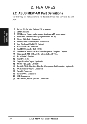
... SECONDARY IDE FLOPPY (Grayed items are optional at the time of purchase.) 12 ASUS MEW-AM User's Manual HARDWARE SETUP 3.1 Motherboard Layout PS2KBMS T: Mouse B: Keyboard USB T: Port 1 B: Port 2 COM1 CPU_FAN Socket 370 FS4 FS3 FS2 External Frequency Selection FS1 FS0 DIMM Socket 1 (64/72... PRINTER GAME_AUDIO VGA Line Out Line In Mic In CD_IN Audio Codec 2 MB SDRAM 2 MB SDRAM Intel 810 Graphics & Memory Controller Hub (GMCH) PCI Slot 1 MEW-AM PCI Slot 2 PCI Slot 3 32-bit PCI Audio Chipset PCI Slot 4 COM2 4Mbit Firmware Hub (FWH) ATX Power Connector (ATXPWR) Row 00 1 2 3...
... SECONDARY IDE FLOPPY (Grayed items are optional at the time of purchase.) 12 ASUS MEW-AM User's Manual HARDWARE SETUP 3.1 Motherboard Layout PS2KBMS T: Mouse B: Keyboard USB T: Port 1 B: Port 2 COM1 CPU_FAN Socket 370 FS4 FS3 FS2 External Frequency Selection FS1 FS0 DIMM Socket 1 (64/72... PRINTER GAME_AUDIO VGA Line Out Line In Mic In CD_IN Audio Codec 2 MB SDRAM 2 MB SDRAM Intel 810 Graphics & Memory Controller Hub (GMCH) PCI Slot 1 MEW-AM PCI Slot 2 PCI Slot 3 32-bit PCI Audio Chipset PCI Slot 4 COM2 4Mbit Firmware Hub (FWH) ATX Power Connector (ATXPWR) Row 00 1 2 3...

MEW-AM User Manual
Page 13
HARDWARE SETUP 3.2 Layout Contents Motherboard Settings 1) FS0, FS1, FS2, FS3, FS4 p.14 CPU External Clock (BUS) Frequency Setting Expansion Slots 1) DIMM1, DIMM2 2) Socket 370 3) PCI1, PCI2, PCI3, PCI4 p.15 ... (20 pins) 3.3 Hardware Setup Procedure Before using your computer, you must complete the following steps: • Check Motherboard Settings • Install Memory Modules • Install the Central Processing Unit (CPU) • Install Expansion Cards • Connect Ribbon Cables, Panel Wires, and Power Supply ASUS MEW-AM User's Manual 13 H/W SETUP Layout Contents 3. 3.
HARDWARE SETUP 3.2 Layout Contents Motherboard Settings 1) FS0, FS1, FS2, FS3, FS4 p.14 CPU External Clock (BUS) Frequency Setting Expansion Slots 1) DIMM1, DIMM2 2) Socket 370 3) PCI1, PCI2, PCI3, PCI4 p.15 ... (20 pins) 3.3 Hardware Setup Procedure Before using your computer, you must complete the following steps: • Check Motherboard Settings • Install Memory Modules • Install the Central Processing Unit (CPU) • Install Expansion Cards • Connect Ribbon Cables, Panel Wires, and Power Supply ASUS MEW-AM User's Manual 13 H/W SETUP Layout Contents 3. 3.
MEW-AM User Manual
Page 14
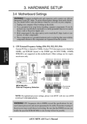
... wrist strap before handling computer components. Hold components by the edges and try not to be possible. 14 ASUS MEW-AM User's Manual Premature wearing of your computer when working on your computer. 1. HARDWARE SETUP 3.4 Motherboard Settings WARNING! To protect them against damage from the system. 1) CPU External Frequency Setting (FS0, FS1, FS2...
... wrist strap before handling computer components. Hold components by the edges and try not to be possible. 14 ASUS MEW-AM User's Manual Premature wearing of your computer when working on your computer. 1. HARDWARE SETUP 3.4 Motherboard Settings WARNING! To protect them against damage from the system. 1) CPU External Frequency Setting (FS0, FS1, FS2...

MEW-AM User Manual
Page 15
..., 256MB DIMM's are available for best performance vs. This chipset does not support ECC. double-sided come in 32, 64, 128, 256MB. ASUS MEW-AM User's Manual 15 stability. • SDRAM chips are generally thinner with higher pin density than EDO (Extended Data Output) chips. •...32, 64, 128MB, or 256MB Total System Memory (Max 512MB) Total Memory x1 x1 = NOTE: At the time this speed. • ASUS motherboards support SPD (Serial Presence Detect) DIMMs. This is required after adding or removing memory. Install memory in any combination as Double-Sided registered memory ...
..., 256MB DIMM's are available for best performance vs. This chipset does not support ECC. double-sided come in 32, 64, 128, 256MB. ASUS MEW-AM User's Manual 15 stability. • SDRAM chips are generally thinner with higher pin density than EDO (Extended Data Output) chips. •...32, 64, 128MB, or 256MB Total System Memory (Max 512MB) Total Memory x1 x1 = NOTE: At the time this speed. • ASUS motherboards support SPD (Serial Presence Detect) DIMMs. This is required after adding or removing memory. Install memory in any combination as Double-Sided registered memory ...

MEW-AM User Manual
Page 16
... determine the DIMM type, check the notches on the DIMM module will only fit in the orientation shown. This motherboard supports four clock signals per DIMM slot. 16 ASUS MEW-AM User's Manual Because the number of the breaks, the module will shift between left, center, or right to ... figure below). 168-Pin DIMM Notch Key Definitions (3.3V) 3. You must be 3.3V Unbuffered for this motherboard. HARDWARE SETUP 3.5.2 DIMM Memory Installation Insert the module(s) as shown. Lock 1 MEW-AM MEW-AM 168-Pin DIMM Sockets 88 Pins 60 Pins 20 Pins FRONT The DIMMs must ask your retailer the...
... determine the DIMM type, check the notches on the DIMM module will only fit in the orientation shown. This motherboard supports four clock signals per DIMM slot. 16 ASUS MEW-AM User's Manual Because the number of the breaks, the module will shift between left, center, or right to ... figure below). 168-Pin DIMM Notch Key Definitions (3.3V) 3. You must be 3.3V Unbuffered for this motherboard. HARDWARE SETUP 3.5.2 DIMM Memory Installation Insert the module(s) as shown. Lock 1 MEW-AM MEW-AM 168-Pin DIMM Sockets 88 Pins 60 Pins 20 Pins FRONT The DIMMs must ask your retailer the...
MEW-AM User Manual
Page 17
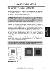
... and Multiple (frequency multiple setting is available only on your CPU fan is required to the motherboard. H/W SETUP Expansion Cards 1 MEW-AM MEW-AM Socket 370 Notch ASUS MEW-AM User's Manual 17 HARDWARE SETUP 3.6 Central Processing Unit (CPU) The motherboard provides a ZIF Socket 370. The CPU that your system. Without sufficient circulation, the processor could...
... and Multiple (frequency multiple setting is available only on your CPU fan is required to the motherboard. H/W SETUP Expansion Cards 1 MEW-AM MEW-AM Socket 370 Notch ASUS MEW-AM User's Manual 17 HARDWARE SETUP 3.6 Central Processing Unit (CPU) The motherboard provides a ZIF Socket 370. The CPU that your system. Without sufficient circulation, the processor could...
MEW-AM User Manual
Page 18
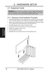
... card, such as jumpers or switches. 2. Replace the computer system's cover. 6. Set up the BIOS if necessary. 7. H/W SETUP Expansion Cards 18 ASUS MEW-AM User's Manual HARDWARE SETUP 3.7 Expansion Cards WARNING! Install the necessary software drivers for possible future use . Make sure that you removed above. 5. .... 3. Remove your computer system's cover and the bracket plate with screw on the slot with the screw you unplug your motherboard and expansion cards. 3.7.1 Expansion Card Installation Procedure 1. Carefully align the card's connectors and press firmly. 4.
... card, such as jumpers or switches. 2. Replace the computer system's cover. 6. Set up the BIOS if necessary. 7. H/W SETUP Expansion Cards 18 ASUS MEW-AM User's Manual HARDWARE SETUP 3.7 Expansion Cards WARNING! Install the necessary software drivers for possible future use . Make sure that you removed above. 5. .... 3. Remove your computer system's cover and the bracket plate with screw on the slot with the screw you unplug your motherboard and expansion cards. 3.7.1 Expansion Card Installation Procedure 1. Carefully align the card's connectors and press firmly. 4.
MEW-AM User Manual
Page 19
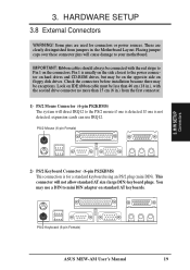
...connectors. Pin 1 is usually on the side closest to the PS/2 mouse if one is not detected, expansion cards can use a DIN to your motherboard. You may be on the opposite side on standard AT keyboards. These are used for a standard keyboard using an PS/2 plug (mini DIN). ...drives, but may be exceptions. PS/2 Mouse (6-pin Female) 3. Check the connectors before installation because there may use IRQ12. PS/2 Keyboard (6-pin Female) ASUS MEW-AM User's Manual 19 3. HARDWARE SETUP 3.8 External Connectors WARNING! If one is for connectors or power sources.
...connectors. Pin 1 is usually on the side closest to the PS/2 mouse if one is not detected, expansion cards can use a DIN to your motherboard. You may be on the opposite side on standard AT keyboards. These are used for a standard keyboard using an PS/2 plug (mini DIN). ...drives, but may be exceptions. PS/2 Mouse (6-pin Female) 3. Check the connectors before installation because there may use IRQ12. PS/2 Keyboard (6-pin Female) ASUS MEW-AM User's Manual 19 3. HARDWARE SETUP 3.8 External Connectors WARNING! If one is for connectors or power sources.

MEW-AM User Manual
Page 20
.... H/W SETUP Connectors 5) Serial Port COM1 Connector (9-pin COM1) One serial port is available using a serial port bracket connected from the motherboard to the serial port. Serial Port (9-pin Male) COM 1 20 ASUS MEW-AM User's Manual See Serial Port A or B in 4.4.1 I /O Device Configuration for settings. See Parallel Port in 4.4.1 I /O Device Configuration for settings...
.... H/W SETUP Connectors 5) Serial Port COM1 Connector (9-pin COM1) One serial port is available using a serial port bracket connected from the motherboard to the serial port. Serial Port (9-pin Male) COM 1 20 ASUS MEW-AM User's Manual See Serial Port A or B in 4.4.1 I /O Device Configuration for settings. See Parallel Port in 4.4.1 I /O Device Configuration for settings...

MEW-AM User Manual
Page 24
...Connectors ATX Power Switch* Reset SW HDLED Power LED * Requires an ATX power supply. 24 ASUS MEW-AM User's Manual Connect the fan's plug to go across the CPU and onboard heatsinks. The CPU and/or motherboard will overheat if there is used . NOTE: The "Rotation" signal cannot be monitored on... the fan manufacturer, the wiring and plug may occur to the motherboard and/or the CPU fan if these pins. 1 MEW-AM CPU Fan Power Rotation +12V GND MEW-AM 12-Volt Cooling Fan Power The following PANEL illustration is no airflow across the onboard heat ...
...Connectors ATX Power Switch* Reset SW HDLED Power LED * Requires an ATX power supply. 24 ASUS MEW-AM User's Manual Connect the fan's plug to go across the CPU and onboard heatsinks. The CPU and/or motherboard will overheat if there is used . NOTE: The "Rotation" signal cannot be monitored on... the fan manufacturer, the wiring and plug may occur to the motherboard and/or the CPU fan if these pins. 1 MEW-AM CPU Fan Power Rotation +12V GND MEW-AM 12-Volt Cooling Fan Power The following PANEL illustration is no airflow across the onboard heat ...

MEW-AM User Manual
Page 28
... the last four numbers of the code displayed on the motherboard. Type COPY D:\AFLASH\AFLASH.EXE A:\ (assuming D is not supported by the ACPI BIOS and therefore, cannot be loaded when you need to reinstall the BIOS ... Writer utility (AFLASH.EXE) to the programmable flash ROM on the upper lefthand corner of the original motherboard BIOS along with certain memory drivers that updates the BIOS by the Flash Memory Writer utility. 28 ASUS MEW-AM User's Manual 4. BIOS SETUP 4.1 Managing and Updating Your BIOS 4.1.1 Upon First Use of the Computer...
... the last four numbers of the code displayed on the motherboard. Type COPY D:\AFLASH\AFLASH.EXE A:\ (assuming D is not supported by the ACPI BIOS and therefore, cannot be loaded when you need to reinstall the BIOS ... Writer utility (AFLASH.EXE) to the programmable flash ROM on the upper lefthand corner of the original motherboard BIOS along with certain memory drivers that updates the BIOS by the Flash Memory Writer utility. 28 ASUS MEW-AM User's Manual 4. BIOS SETUP 4.1 Managing and Updating Your BIOS 4.1.1 Upon First Use of the Computer...

MEW-AM User Manual
Page 31
...designed to make changes to use the Setup program, at some time in 4.1 Managing and Updating Your BIOS. BIOS SETUP Program Information ASUS MEW-AM User's Manual 31 This section describes how to configure your system, or prompted to call up the computer, the system provides you... in the future you may not reflect your computer. The utility is constantly being updated, the following BIOS screens and descriptions are installing a motherboard, reconfiguring your system using this program. Press to call Setup, restart the system by pressing + + , or by turning the system off...
...designed to make changes to use the Setup program, at some time in 4.1 Managing and Updating Your BIOS. BIOS SETUP Program Information ASUS MEW-AM User's Manual 31 This section describes how to configure your system, or prompted to call up the computer, the system provides you... in the future you may not reflect your computer. The utility is constantly being updated, the following BIOS screens and descriptions are installing a motherboard, reconfiguring your system using this program. Press to call Setup, restart the system by pressing + + , or by turning the system off...


