
MAXIMUS VI HERO User's Manual
Page 1
Motherboard MAXIMUS VI HERO
Motherboard MAXIMUS VI HERO
MAXIMUS VI HERO User's Manual
Page 3
Contents Safety information...vi About this guide...vii MAXIMUS VI HERO specifications summary ix Package contents...xiii Installation tools and components xiv Chapter 1: Product Introduction 1.1 Special features 1-1 1.1.1 Product highlights 1-1 1.1.2 ROG Gaming Features 1-2 1.1.3 ROG Exclusive Features 1-3 1.1.4 ASUS Special Features 1-3 1.1.5 ROG rich bundled software 1-4 1.2 Motherboard overview 1-5 1.2.1 Before you proceed 1-5 1.2.2 Motherboard layout 1-6 1.2.3 Central Processing Unit (CPU 1-8 1.2.4 System memory 1-9 1.2.5 Expansion slots 1-23...
Contents Safety information...vi About this guide...vii MAXIMUS VI HERO specifications summary ix Package contents...xiii Installation tools and components xiv Chapter 1: Product Introduction 1.1 Special features 1-1 1.1.1 Product highlights 1-1 1.1.2 ROG Gaming Features 1-2 1.1.3 ROG Exclusive Features 1-3 1.1.4 ASUS Special Features 1-3 1.1.5 ROG rich bundled software 1-4 1.2 Motherboard overview 1-5 1.2.1 Before you proceed 1-5 1.2.2 Motherboard layout 1-6 1.2.3 Central Processing Unit (CPU 1-8 1.2.4 System memory 1-9 1.2.5 Expansion slots 1-23...
MAXIMUS VI HERO User's Manual
Page 6
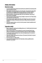
...8226; Avoid dust, humidity, and temperature extremes. If you add a device. • Before connecting or removing signal cables from the motherboard, ensure that all the manuals that came with the product, contact a qualified service technician or your retailer. Safety information Electrical safety &#...correct voltage in any damage, contact your retailer. Operation safety • Before installing the motherboard and adding devices on a stable surface. • If you are connected. vi If you are not sure about the voltage of the electrical outlet you encounter technical problems...
...8226; Avoid dust, humidity, and temperature extremes. If you add a device. • Before connecting or removing signal cables from the motherboard, ensure that all the manuals that came with the product, contact a qualified service technician or your retailer. Safety information Electrical safety &#...correct voltage in any damage, contact your retailer. Operation safety • Before installing the motherboard and adding devices on a stable surface. • If you are connected. vi If you are not sure about the voltage of the electrical outlet you encounter technical problems...

MAXIMUS VI HERO User's Manual
Page 7
...products. How this guide This user guide contains the information you have been added by your dealer. ASUS websites The ASUS website provides updated information on the motherboard. • Chapter 2: Basic Installation This chapter lists the hardware setup procedures that may include optional documentation... settings through the BIOS Setup menus. Where to find more information Refer to the ASUS contact information. 2. Detailed descriptions of the BIOS parameters are not part of the motherboard and the new technology it supports. Refer to the following parts: • Chapter...
...products. How this guide This user guide contains the information you have been added by your dealer. ASUS websites The ASUS website provides updated information on the motherboard. • Chapter 2: Basic Installation This chapter lists the hardware setup procedures that may include optional documentation... settings through the BIOS Setup menus. Where to find more information Refer to the ASUS contact information. 2. Detailed descriptions of the BIOS parameters are not part of the motherboard and the new technology it supports. Refer to the following parts: • Chapter...
MAXIMUS VI HERO User's Manual
Page 13
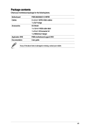
xiii Package contents Check your motherboard package for the following items. Motherboard Cables Accessories Application DVD Documentation ROG MAXIMUS VI HERO 3 x 2-in-1 SATA 6 Gb/s cables 1 x SLI® bridge I/O Shield 1 x 12-in-1 ROG cable label 1 x 2-in-1 Q-Connector kit 1 x ROG Door Hanger ROG motherboard support DVD User guide If any of the above items is damaged or missing, contact your retailer.
xiii Package contents Check your motherboard package for the following items. Motherboard Cables Accessories Application DVD Documentation ROG MAXIMUS VI HERO 3 x 2-in-1 SATA 6 Gb/s cables 1 x SLI® bridge I/O Shield 1 x 12-in-1 ROG cable label 1 x 2-in-1 Q-Connector kit 1 x ROG Door Hanger ROG motherboard support DVD User guide If any of the above items is damaged or missing, contact your retailer.

MAXIMUS VI HERO User's Manual
Page 14
Installation tools and components 1 bag of screws Philips (cross) screwdriver PC chassis Power supply unit Intel LGA 1150 CPU Intel LGA 1150 compatible CPU Fan DDR3 DIMM SATA hard disk drive SATA optical disc drive (optional) Graphics card (optional) The tools and components in the table above are not included in the motherboard package. xiv
Installation tools and components 1 bag of screws Philips (cross) screwdriver PC chassis Power supply unit Intel LGA 1150 CPU Intel LGA 1150 compatible CPU Fan DDR3 DIMM SATA hard disk drive SATA optical disc drive (optional) Graphics card (optional) The tools and components in the table above are not included in the motherboard package. xiv
MAXIMUS VI HERO User's Manual
Page 15
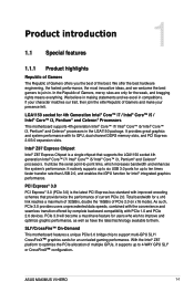
... ideas, and we excel in the LGA1150 package. If your presence felt. It utilizes the serial point-to join in x16 mode). Chapter 1 ASUS MAXIMUS VI HERO 1-1 In the Republic of PCIe 2.0 (in . It provides great graphics and system performance with PCIe 1.0 and PCIe 2.0 devices. It natively... double the 16GB/s of Gamers, mercy rules are only for Intel® integrated graphics performance. SLI®/CrossFire™ On-Demand This motherboard features a unique PCIe 3.0 bridge chip to ten times faster transfer rate than USB 2.0, and enables the iGPU function for the weak, and...
... ideas, and we excel in the LGA1150 package. If your presence felt. It utilizes the serial point-to join in x16 mode). Chapter 1 ASUS MAXIMUS VI HERO 1-1 In the Republic of PCIe 2.0 (in . It provides great graphics and system performance with PCIe 1.0 and PCIe 2.0 devices. It natively... double the 16GB/s of Gamers, mercy rules are only for Intel® integrated graphics performance. SLI®/CrossFire™ On-Demand This motherboard features a unique PCIe 3.0 bridge chip to ten times faster transfer rate than USB 2.0, and enables the iGPU function for the weak, and...
MAXIMUS VI HERO User's Manual
Page 16
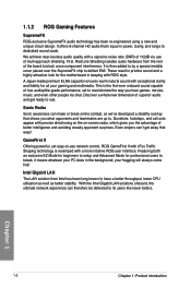
... been re-engineered using a new and unique circuit design. A Japan-made premium ELNA capacitor ensures warm natural sound with exceptional clarity and fidelity for the motherboard in power, clarity, and range to deflect EMI. It offers 8-channel HD audio that's equal in keeping with precise directioning on the on-screen radar...
... been re-engineered using a new and unique circuit design. A Japan-made premium ELNA capacitor ensures warm natural sound with exceptional clarity and fidelity for the motherboard in power, clarity, and range to deflect EMI. It offers 8-channel HD audio that's equal in keeping with precise directioning on the on-screen radar...
MAXIMUS VI HERO User's Manual
Page 17
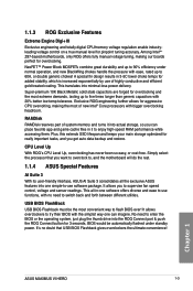
...exponentially by use functions, with no doubt that you to try their BIOS with bigger overclocking headroom. Among Intelxzc Z87-based motherboards, only ROG offers fully manual voltage tuning, making the most extreme demands, lasting up to enjoy high-speed RAM performance ...files in -one simple-to , and the motherboard will do the rest. 1.1.4 ASUS Special Features AI Suite 3 With its user-friendly interface, ASUS AI Suite 3 consolidates all -in it into the ROG Connect port & push the ROG Connect button for pinpoint tuning accuracy. Chapter 1 ASUS MAXIMUS VI HERO 1-3
...exponentially by use functions, with no doubt that you to try their BIOS with bigger overclocking headroom. Among Intelxzc Z87-based motherboards, only ROG offers fully manual voltage tuning, making the most extreme demands, lasting up to enjoy high-speed RAM performance ...files in -one simple-to , and the motherboard will do the rest. 1.1.4 ASUS Special Features AI Suite 3 With its user-friendly interface, ASUS AI Suite 3 consolidates all -in it into the ROG Connect port & push the ROG Connect button for pinpoint tuning accuracy. Chapter 1 ASUS MAXIMUS VI HERO 1-3

MAXIMUS VI HERO User's Manual
Page 19
Chapter 1 ASUS MAXIMUS VI HERO 1-5 1.2 Motherboard overview 1.2.1 Before you proceed Take note of the following precautions before you install or remove any component B�e�f�o�r�e�h��a&#...;ro��u�n�d�e�d� object or a metal object, such as the power supply case, to avoid damaging them due to the motherboard, peripherals, or components. Failure to do so may cause severe damage to static electricity H��o�ld��c�o�m��p�...
Chapter 1 ASUS MAXIMUS VI HERO 1-5 1.2 Motherboard overview 1.2.1 Before you proceed Take note of the following precautions before you install or remove any component B�e�f�o�r�e�h��a&#...;ro��u�n�d�e�d� object or a metal object, such as the power supply case, to avoid damaging them due to the motherboard, peripherals, or components. Failure to do so may cause severe damage to static electricity H��o�ld��c�o�m��p�...
MAXIMUS VI HERO User's Manual
Page 20
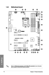
1.2.2 Motherboard layout Chapter 1 Refer to 1.2.9 Internal connectors and 2.3.1 Rear I/O connection for more information about rear panel connectors and internal connectors. 1-6 Chapter 1: Product introduction
1.2.2 Motherboard layout Chapter 1 Refer to 1.2.9 Internal connectors and 2.3.1 Rear I/O connection for more information about rear panel connectors and internal connectors. 1-6 Chapter 1: Product introduction
MAXIMUS VI HERO User's Manual
Page 22
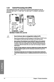
...;�e�C��P�U��. • Ensure that you see any damage to the PnP cap/socket contacts/motherboard components. Chapter 1 1-8 Chapter 1: Product introduction Contact your retailer immediately if the PnP cap is ��o�n�...th��e�s�o��c�k�e�t�a�n�d� the socket contacts are not bent. ASUS will shoulder the cost of the PnP cap. E�n�s�u�r�e��t�h�a�t�a�...
...;�e�C��P�U��. • Ensure that you see any damage to the PnP cap/socket contacts/motherboard components. Chapter 1 1-8 Chapter 1: Product introduction Contact your retailer immediately if the PnP cap is ��o�n�...th��e�s�o��c�k�e�t�a�n�d� the socket contacts are not bent. ASUS will shoulder the cost of the PnP cap. E�n�s�u�r�e��t�h�a�t�a�...

MAXIMUS VI HERO User's Manual
Page 23
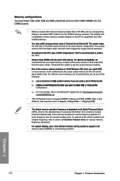
A DDR3 module is notched differently from a DDR or DDR2 module. Recommended memory configurations Chapter 1 ASUS MAXIMUS VI HERO 1-9 1.2.4 System memory The motherboard comes with four Double Data Rate 3 (DDR3) Dual Inline Memory Modules (DIMM) slots. DO NOT install a DDR or DDR2 memory module to the DDR3 slot.
A DDR3 module is notched differently from a DDR or DDR2 module. Recommended memory configurations Chapter 1 ASUS MAXIMUS VI HERO 1-9 1.2.4 System memory The motherboard comes with four Double Data Rate 3 (DDR3) Dual Inline Memory Modules (DIMM) slots. DO NOT install a DDR or DDR2 memory module to the DDR3 slot.
MAXIMUS VI HERO User's Manual
Page 24
...65533;���o���r���m��o�r�e�o��n�t�h�e� motherboard. Check with memory frequency higher than the vendor-marked value. A�l�w�a�y�s��i�n�s&#...;�S�. For effective use of memory, we recommend that you do any of these memory modules depend on the motherboard, the actual usable memory for the dual-channel configuration. To operate at the vendor-marked or at http://support.microsoft....
...65533;���o���r���m��o�r�e�o��n�t�h�e� motherboard. Check with memory frequency higher than the vendor-marked value. A�l�w�a�y�s��i�n�s&#...;�S�. For effective use of memory, we recommend that you do any of these memory modules depend on the motherboard, the actual usable memory for the dual-channel configuration. To operate at the vendor-marked or at http://support.microsoft....

MAXIMUS VI HERO User's Manual
Page 37
Failure to do so may cause you physical injury and damage motherboard components. Chapter 1 Slot No. 1 2 3 4 5 6 Slot Description PCIe 2.0 x1_1 slot PCIe 3.0/2.0 x16/x8_1 slot PCIe 2.0 x1_2 slot PCIe 3.0/2.0 x16/x8_2 slot PCIe 2.0 x1_3 slot PCIe 3.0/2.0 x4_3 slot ASUS MAXIMUS VI HERO 1-23 1.2.5 Expansion slots Unplug the power cord before adding or removing expansion cards.
Failure to do so may cause you physical injury and damage motherboard components. Chapter 1 Slot No. 1 2 3 4 5 6 Slot Description PCIe 2.0 x1_1 slot PCIe 3.0/2.0 x16/x8_1 slot PCIe 2.0 x1_2 slot PCIe 3.0/2.0 x16/x8_2 slot PCIe 2.0 x1_3 slot PCIe 3.0/2.0 x4_3 slot ASUS MAXIMUS VI HERO 1-23 1.2.5 Expansion slots Unplug the power cord before adding or removing expansion cards.
MAXIMUS VI HERO User's Manual
Page 38
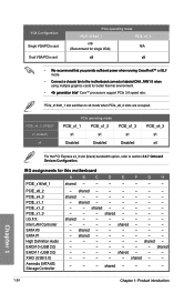
... LAN Controller SATA #0 SATA #1 High Definition Audio EHCI# 0 (USB 2.0) EHCI# 1 (USB 2.0) XHCI (USB 3.0) Asmedia SATA 6G Storage Controller - shared - - - - - - - - - - - shared - - - - - - - - shared - - - - IRQ assignments for this motherboard A B C D E F G H PCIE_x16/x8_1 shared - - - - - - - shared - - - - - - - - - - - - PCIe_x16/x8_1 slot switches to x8 mode when PCIe_x8_2 slots are occupied.
... LAN Controller SATA #0 SATA #1 High Definition Audio EHCI# 0 (USB 2.0) EHCI# 1 (USB 2.0) XHCI (USB 3.0) Asmedia SATA 6G Storage Controller - shared - - - - - - - - - - - shared - - - - - - - - shared - - - - IRQ assignments for this motherboard A B C D E F G H PCIE_x16/x8_1 shared - - - - - - - shared - - - - - - - - - - - - PCIe_x16/x8_1 slot switches to x8 mode when PCIe_x8_2 slots are occupied.

MAXIMUS VI HERO User's Manual
Page 39
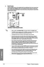
The button also lights up the system. Reset button Press the reset button to enhance system performance. 1. Power-on button The motherboard comes with a power-on button that you to fine-tune performance when working on a bare or open-case system. This ... the system is ideal for overclockers and gamers who continually change settings to reboot the system. Chapter 1 ASUS MAXIMUS VI HERO 1-25 1.2.6 Onboard buttons and switches Onboard switches and buttons allow you should shut down the system and unplug the power cable before removing or installing any motherboard component. 2.
The button also lights up the system. Reset button Press the reset button to enhance system performance. 1. Power-on button The motherboard comes with a power-on button that you to fine-tune performance when working on a bare or open-case system. This ... the system is ideal for overclockers and gamers who continually change settings to reboot the system. Chapter 1 ASUS MAXIMUS VI HERO 1-25 1.2.6 Onboard buttons and switches Onboard switches and buttons allow you should shut down the system and unplug the power cable before removing or installing any motherboard component. 2.
MAXIMUS VI HERO User's Manual
Page 40
... MemOK! The blinking speed of the MEMOK_LED. • The MEMOK_LED also lights up when the DIMM is tested. Replace the DIMMs with the motherboard may cause system boot failure, triggering the MEMOK_LED near the MemOK! switch to memory tuning requirement, the system automatically reboots when each timing set ... settings. • Refer to section 1.2.8 Onboard LEDs for the system to light-up due to the latest BIOS version from the ASUS website at www.asus.com. • If you download and update to BIOS overclocking, press the MemOK! button Installing DIMMs that you turn off the ...
... MemOK! The blinking speed of the MEMOK_LED. • The MEMOK_LED also lights up when the DIMM is tested. Replace the DIMMs with the motherboard may cause system boot failure, triggering the MEMOK_LED near the MemOK! switch to memory tuning requirement, the system automatically reboots when each timing set ... settings. • Refer to section 1.2.8 Onboard LEDs for the system to light-up due to the latest BIOS version from the ASUS website at www.asus.com. • If you download and update to BIOS overclocking, press the MemOK! button Installing DIMMs that you turn off the ...

MAXIMUS VI HERO User's Manual
Page 43
MemOK! is no hard disk drive connected to indicate the hard disk activity. The LED does not light up when there is enabled before POST. It blinks when data is designed to the motherboard or when the hard disk drive does not function. 2. 1.2.8 Onboard LEDs 1. Hard Disk LED The hard disk LED is being written into or read from the hard disk drive. Chapter 1 ASUS MAXIMUS VI HERO 1-29 LED Blinking: Indicates that MemOK!
MemOK! is no hard disk drive connected to indicate the hard disk activity. The LED does not light up when there is enabled before POST. It blinks when data is designed to the motherboard or when the hard disk drive does not function. 2. 1.2.8 Onboard LEDs 1. Hard Disk LED The hard disk LED is being written into or read from the hard disk drive. Chapter 1 ASUS MAXIMUS VI HERO 1-29 LED Blinking: Indicates that MemOK!

MAXIMUS VI HERO User's Manual
Page 44
Chapter 1 1-30 Chapter 1: Product introduction This user-friendly design provides an intuitive way to locate the root problem within seconds. Q LED Q LEDs check key components (CPU, DRAM, VGA card, and booting devices) in sequence during motherboard booting process. If an error is found , the corresponding LED will continue lighting until the problem is solved. 3.
Chapter 1 1-30 Chapter 1: Product introduction This user-friendly design provides an intuitive way to locate the root problem within seconds. Q LED Q LEDs check key components (CPU, DRAM, VGA card, and booting devices) in sequence during motherboard booting process. If an error is found , the corresponding LED will continue lighting until the problem is solved. 3.


