MAXIMUS VI HERO User's Manual
Page 3
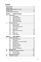
...vi About this guide...vii MAXIMUS VI HERO specifications summary ix Package contents...xiii Installation tools and components xiv Chapter 1: Product Introduction 1.1 Special features 1-1 1.1.1 Product highlights 1-1 1.1.2 ROG Gaming Features 1-2 1.1.3 ROG Exclusive Features 1-3 1.1.4 ASUS... Motherboard installation 2-1 2.1.2 CPU installation 2-3 2.1.3 CPU heatsink and fan assembly installation 2-4 2.1.4 DIMM installation 2-6 2.1.5 ATX Power connection 2-7 2.1.6 SATA device connection 2-8 2.1.7 Front I/O Connector 2-9 2.1.8 Expansion Card installation 2-10 2.2 BIOS...
...vi About this guide...vii MAXIMUS VI HERO specifications summary ix Package contents...xiii Installation tools and components xiv Chapter 1: Product Introduction 1.1 Special features 1-1 1.1.1 Product highlights 1-1 1.1.2 ROG Gaming Features 1-2 1.1.3 ROG Exclusive Features 1-3 1.1.4 ASUS... Motherboard installation 2-1 2.1.2 CPU installation 2-3 2.1.3 CPU heatsink and fan assembly installation 2-4 2.1.4 DIMM installation 2-6 2.1.5 ATX Power connection 2-7 2.1.6 SATA device connection 2-8 2.1.7 Front I/O Connector 2-9 2.1.8 Expansion Card installation 2-10 2.2 BIOS...
MAXIMUS VI HERO User's Manual
Page 12
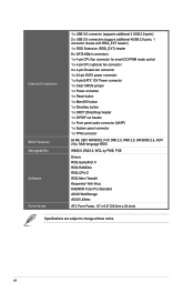
....0, DMI2.0, WOL by PME, PXE Drivers ROG GameFirst II ROG RAMDisk ROG CPU-Z ROG Mem TweakIt Kaspersky® Anti-Virus DAEMON Tools Pro Standard ASUS WebStorage ASUS Utilities ATX Form Factor, 12" x 9.6" (30.5cm x 24.4cm) Specifications are subject to change without notice. Internal Connectors BIOS Features Manageability Software Form Factor 1 x USB 3.0 connector...
....0, DMI2.0, WOL by PME, PXE Drivers ROG GameFirst II ROG RAMDisk ROG CPU-Z ROG Mem TweakIt Kaspersky® Anti-Virus DAEMON Tools Pro Standard ASUS WebStorage ASUS Utilities ATX Form Factor, 12" x 9.6" (30.5cm x 24.4cm) Specifications are subject to change without notice. Internal Connectors BIOS Features Manageability Software Form Factor 1 x USB 3.0 connector...

MAXIMUS VI HERO User's Manual
Page 19
Chapter 1 ASUS MAXIMUS VI HERO 1-5 1.2 Motherboard overview 1.2.1 Before you proceed Take note of the following precautions before you install or remove any component B�e�f�o�r�e�h�&#... you install motherboard components or change any motherboard settings. • Unplug the power cord from the wall socket before touching any component, ensure that the ATX power supply is switched off or the power cord is detached from the power supply. Failure to do so may cause severe damage to static...
Chapter 1 ASUS MAXIMUS VI HERO 1-5 1.2 Motherboard overview 1.2.1 Before you proceed Take note of the following precautions before you install or remove any component B�e�f�o�r�e�h�&#... you install motherboard components or change any motherboard settings. • Unplug the power cord from the wall socket before touching any component, ensure that the ATX power supply is switched off or the power cord is detached from the power supply. Failure to do so may cause severe damage to static...
MAXIMUS VI HERO User's Manual
Page 21
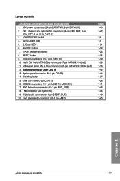
... 1-39 1-45 1-44 1-27 1-28 1-41 1-46 1-46 1-40 1-40 Chapter 1 ASUS MAXIMUS VI HERO 1-7 RESET button 9. USB1314) 17. button 7. START (Power-on) button 8. Digital audio connector (4-1 pin SPDIF_OUT) 20. USB 3.0 connectors (20-1 pin USB3_12) 10. Clear RTC RAM (3-pin CLRTC) 16. ATX power connectors (24-pin EATXPWR; 8-pin EATX12V) 2. USB 2.0 connectors (10-1 pin USB1112...
... 1-39 1-45 1-44 1-27 1-28 1-41 1-46 1-46 1-40 1-40 Chapter 1 ASUS MAXIMUS VI HERO 1-7 RESET button 9. USB1314) 17. button 7. START (Power-on) button 8. Digital audio connector (4-1 pin SPDIF_OUT) 20. USB 3.0 connectors (20-1 pin USB3_12) 10. Clear RTC RAM (3-pin CLRTC) 16. ATX power connectors (24-pin EATXPWR; 8-pin EATX12V) 2. USB 2.0 connectors (10-1 pin USB1112...

MAXIMUS VI HERO User's Manual
Page 57
...;o�n�f�ig�u�r�i�n�g�a� system with ATX 12 V Specification 2.0 (or later version) and provides a minimum power of 350 W. ASUS MAXIMUS VI HERO 1-43 Chapter 1 D�o��n�o�t�f�o�r�g�...65533;y�s�t�e�m��, refer to the Recommended Power Supply Wattage Calculator at http://support.asus. If�y�o��u�a��re��u�n�c�e��rt�...
...;o�n�f�ig�u�r�i�n�g�a� system with ATX 12 V Specification 2.0 (or later version) and provides a minimum power of 350 W. ASUS MAXIMUS VI HERO 1-43 Chapter 1 D�o��n�o�t�f�o�r�g�...65533;y�s�t�e�m��, refer to the Recommended Power Supply Wattage Calculator at http://support.asus. If�y�o��u�a��re��u�n�c�e��rt�...

MAXIMUS VI HERO User's Manual
Page 58
... SPEAKER) This 4-pin connector is for the chassis-mounted system warning speaker. Connect the chassis power LED cable to hear system beeps and warnings. • ATX power button/soft-off mode depending on or puts the system in sleep mode. • Hard disk drive activity LED (2-pin HDD_LED) This 2-pin connector...
... SPEAKER) This 4-pin connector is for the chassis-mounted system warning speaker. Connect the chassis power LED cable to hear system beeps and warnings. • ATX power button/soft-off mode depending on or puts the system in sleep mode. • Hard disk drive activity LED (2-pin HDD_LED) This 2-pin connector...

MAXIMUS VI HERO User's Manual
Page 67
2.1.5 1 ATX Power connection 2 OR OR Chapter 2 ASUS MAXIMUS VI HERO 2-7
2.1.5 1 ATX Power connection 2 OR OR Chapter 2 ASUS MAXIMUS VI HERO 2-7

MAXIMUS VI HERO User's Manual
Page 77
...are off mode, depending on , hold down the key to a power outlet that all the connections, replace the system case cover. 2. Chapter 2 ASUS MAXIMUS VI HERO 2-17 If your retailer for more than four seconds to put the system on sleep mode or soft-off . 3. Connect the power cord to enter... detected Hardware component failure 7. Check the jumper settings and connections or call your monitor complies with ATX power supplies, the system LED lights up or change from the time you press the ATX power button. For systems with the "green" standards or if it has a "power standby"...
...are off mode, depending on , hold down the key to a power outlet that all the connections, replace the system case cover. 2. Chapter 2 ASUS MAXIMUS VI HERO 2-17 If your retailer for more than four seconds to put the system on sleep mode or soft-off . 3. Connect the power cord to enter... detected Hardware component failure 7. Check the jumper settings and connections or call your monitor complies with ATX power supplies, the system LED lights up or change from the time you press the ATX power button. For systems with the "green" standards or if it has a "power standby"...


