MAXIMUS VI HERO User's Manual
Page 15
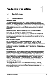
...Pentium® and Celeron® processors. With the Intel® Z87 platform to optimize the PCIe allocation of PCIe 2.0 (in . Chapter 1 ASUS MAXIMUS VI HERO 1-1 It utilizes the serial point-to 4-WAY GPU SLI® or CrossFireX™ configuration�. It natively supports up to six USB 3.0 ... become a must-have feature for users who wish to improve and optimize graphic performance, as well as have the latest technology available to ten times faster transfer rate than USB 2.0, and enables the iGPU function for an unrivaled gaming performance. SLI®/CrossFire™...
...Pentium® and Celeron® processors. With the Intel® Z87 platform to optimize the PCIe allocation of PCIe 2.0 (in . Chapter 1 ASUS MAXIMUS VI HERO 1-1 It utilizes the serial point-to 4-WAY GPU SLI® or CrossFireX™ configuration�. It natively supports up to six USB 3.0 ... become a must-have feature for users who wish to improve and optimize graphic performance, as well as have the latest technology available to ten times faster transfer rate than USB 2.0, and enables the iGPU function for an unrivaled gaming performance. SLI®/CrossFire™...

MAXIMUS VI HERO User's Manual
Page 48
... or possible CPU cache error CPU micro-code is not found or micro-code update is failed Internal CPU error Reset PPI is not available Reserved for future AMI error codes S3 Resume is stared (S3 Resume PPI is called by the DXE IPL) S3 Boot Script execution ... started Recovery firmware image is found Recovery firmware image is loaded Reserved for future AMI progress codes Recovery PPI is started DXE IPL is not available (continued on the next page) Chapter 1 1-34 Chapter 1: Product introduction F7 F8 Description Post-Memory PCH initialization is started Memory initialization error. Q-...
... or possible CPU cache error CPU micro-code is not found or micro-code update is failed Internal CPU error Reset PPI is not available Reserved for future AMI error codes S3 Resume is stared (S3 Resume PPI is called by the DXE IPL) S3 Boot Script execution ... started Recovery firmware image is found Recovery firmware image is loaded Reserved for future AMI progress codes Recovery PPI is started DXE IPL is not available (continued on the next page) Chapter 1 1-34 Chapter 1: Product introduction F7 F8 Description Post-Memory PCH initialization is started Memory initialization error. Q-...

MAXIMUS VI HERO User's Manual
Page 51
... of Resources No Space for Legacy Option ROM No Console Output Devices are found No Console Input Devices are not available PCI resource allocation error. Interrupt controller is in PIC mode. Chapter 1 ASUS MAXIMUS VI HERO 1-37 Out of the Architectural Protocols are found Invalid password Error loading Boot Option (LoadImage returned error) Boot Option...
... of Resources No Space for Legacy Option ROM No Console Output Devices are found No Console Input Devices are not available PCI resource allocation error. Interrupt controller is in PIC mode. Chapter 1 ASUS MAXIMUS VI HERO 1-37 Out of the Architectural Protocols are found Invalid password Error loading Boot Option (LoadImage returned error) Boot Option...

MAXIMUS VI HERO User's Manual
Page 54
... of the front panel audio I /O module that you want to connect a high-definition or an AC'97 front panel audio module to this connector to avail of the system chassis. 4. Digital audio connector (4-1 pin SPDIF_OUT) This connector is for an additional Sony/Philips Digital Interface (S/PDIF) port. The S/PDIF module is...
... of the front panel audio I /O module that you want to connect a high-definition or an AC'97 front panel audio module to this connector to avail of the system chassis. 4. Digital audio connector (4-1 pin SPDIF_OUT) This connector is for an additional Sony/Philips Digital Interface (S/PDIF) port. The S/PDIF module is...
MAXIMUS VI HERO User's Manual
Page 81
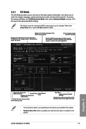
... and resets the system, or enters the Advanced Mode Chapter 3 Selects the Advanced Mode functions Displays Normal the Advanced mode ASUS mode Optimal mode menus Selects the boot device priority Power Saving mode Boot Menu Loads optimized default settings Displays the system properties...allows you installed to the system. • ��T�h�e Boot Menu (F8) button is available only when the boot device is installed to the system. ASUS MAXIMUS VI HERO 3-3 To access the Advanced Mode, click Exit/Advanced Mode, then select Advanced Mode or press hot key...
... and resets the system, or enters the Advanced Mode Chapter 3 Selects the Advanced Mode functions Displays Normal the Advanced mode ASUS mode Optimal mode menus Selects the boot device priority Power Saving mode Boot Menu Loads optimized default settings Displays the system properties...allows you installed to the system. • ��T�h�e Boot Menu (F8) button is available only when the boot device is installed to the system. ASUS MAXIMUS VI HERO 3-3 To access the Advanced Mode, click Exit/Advanced Mode, then select Advanced Mode or press hot key...

MAXIMUS VI HERO User's Manual
Page 120
SATA Support [All Sata D...] USB Support [Partial In...] [Disabled] All USB devices will not be available until OS boot up for a fastest POST time. [Full Initialization] All USB devices will be available during POST. 3-42 Chapter 3: BIOS setup Chapter 3 3.8 Boot menu The Boot menu items allow you to [Enabled]. Network ... to go back to its normal boot speed. [Enabled] Allows your system to disable or have full system control of the PS/2 devices' availability during POST. P/2 Keyboard and Mouse Support [Auto] Allows you set the Fast Boot to change the system boot options.
SATA Support [All Sata D...] USB Support [Partial In...] [Disabled] All USB devices will not be available until OS boot up for a fastest POST time. [Full Initialization] All USB devices will be available during POST. 3-42 Chapter 3: BIOS setup Chapter 3 3.8 Boot menu The Boot menu items allow you to [Enabled]. Network ... to go back to its normal boot speed. [Enabled] Allows your system to disable or have full system control of the PS/2 devices' availability during POST. P/2 Keyboard and Mouse Support [Auto] Allows you set the Fast Boot to change the system boot options.

MAXIMUS VI HERO User's Manual
Page 125
...between [Yes] or [No], then press to AHCI. Do not turn off the system during the process. • Secure Erase is only available in AHCI mode. Ensure to set the SATA mode to confirm your choice. When you to erase the contents of your SSD, restoring it to...special functions. Secure Erase completely and safely cleans your SSD may take a while depending on an incompatible SSD. • The time to run ASUS EZ Flash 2. ASUS MAXIMUS VI HERO 3-47 Chapter 3 To launch ROG SSD Secure Erase, click Tool > ROG SSD Secure Erase on Intel SATA port. For more information about ...
...between [Yes] or [No], then press to AHCI. Do not turn off the system during the process. • Secure Erase is only available in AHCI mode. Ensure to set the SATA mode to confirm your choice. When you to erase the contents of your SSD, restoring it to...special functions. Secure Erase completely and safely cleans your SSD may take a while depending on an incompatible SSD. • The time to run ASUS EZ Flash 2. ASUS MAXIMUS VI HERO 3-47 Chapter 3 To launch ROG SSD Secure Erase, click Tool > ROG SSD Secure Erase on Intel SATA port. For more information about ...

MAXIMUS VI HERO User's Manual
Page 126
... process is the result of your PC must be due to unlock the SSD in the software before proceeding with the Secure Erase. Displays the available SSDs Click to booting. If the drive is frozen, a power off or hard reset of a BIOS protective measure. You have to a third party ...software that do not have password protection by ASUS. The BIOS guards drives that uses a different password defined by freezing them prior to start the SSD Secure Erase Status definition: Frozen The frozen state...
... process is the result of your PC must be due to unlock the SSD in the software before proceeding with the Secure Erase. Displays the available SSDs Click to booting. If the drive is frozen, a power off or hard reset of a BIOS protective measure. You have to a third party ...software that do not have password protection by ASUS. The BIOS guards drives that uses a different password defined by freezing them prior to start the SSD Secure Erase Status definition: Frozen The frozen state...

MAXIMUS VI HERO User's Manual
Page 130
... your changes to ensure the values you selected are finished making your changes. When you select this option or if you press , a confirmation window appears. ASUS EZ Mode This option allows you to load the default values. When you select this option from the Exit menu to the BIOS items. You... to enter the EZ Mode screen. 3.10 Exit menu The Exit menu items allow you to load the optimal default values for each of the available filesystem devices. 3-52 Chapter 3: BIOS setup Chapter 3
... your changes to ensure the values you selected are finished making your changes. When you select this option or if you press , a confirmation window appears. ASUS EZ Mode This option allows you to load the default values. When you select this option from the Exit menu to the BIOS items. You... to enter the EZ Mode screen. 3.10 Exit menu The Exit menu items allow you to load the optimal default values for each of the available filesystem devices. 3-52 Chapter 3: BIOS setup Chapter 3

MAXIMUS VI HERO User's Manual
Page 138
...videos. The software manual files are included in Portable Document Format (PDF). Support DVD main menu The Drivers menu shows the available device drivers if the system detects installed devices. Install the Adobe® Acrobat® Reader from the Utilities tab before opening ... manuals The software manuals are in the support DVD. From the Manual folder, open the folder of supplementary user manuals. Click Manual tab > ASUS Motherboard Utility Guide. 2. Click the Contact tab to read about your motherboard's utility guide: 1. Chapter 4 4-2 Chapter 4: Software support To ...
...videos. The software manual files are included in Portable Document Format (PDF). Support DVD main menu The Drivers menu shows the available device drivers if the system detects installed devices. Install the Adobe® Acrobat® Reader from the Utilities tab before opening ... manuals The software manuals are in the support DVD. From the Manual folder, open the folder of supplementary user manuals. Click Manual tab > ASUS Motherboard Utility Guide. 2. Click the Contact tab to read about your motherboard's utility guide: 1. Chapter 4 4-2 Chapter 4: Software support To ...

MAXIMUS VI HERO User's Manual
Page 153
... for more details. USB BIOS Flashback screen Set a schedule for the BIOS Update download Click to check for a new BIOS update available for download Current BIOS information Click to cancel the download schedule setting Click to quickly check for the latest... storage device. Wait for the system to section 2.3.1 Rear I/O connection of days for New BIOS Update. To download the updated BIOS: 1. Chapter 4 ASUS MAXIMUS VI HERO 4-17 Refer to check the latest BIOS version. In the Download Setting field, tick Schedule (days) then select the number of your computer's USB port...
... for more details. USB BIOS Flashback screen Set a schedule for the BIOS Update download Click to check for a new BIOS update available for download Current BIOS information Click to cancel the download schedule setting Click to quickly check for the latest... storage device. Wait for the system to section 2.3.1 Rear I/O connection of days for New BIOS Update. To download the updated BIOS: 1. Chapter 4 ASUS MAXIMUS VI HERO 4-17 Refer to check the latest BIOS version. In the Download Setting field, tick Schedule (days) then select the number of your computer's USB port...

MAXIMUS VI HERO User's Manual
Page 159
To delete an existing RAMDisk drive: Click to delete the existing RAMDisk Creating/Deleting a Junction Point A junction point creates a link that remaps the original contents into the RAMDisk, enabling access to the desired application or data to finish adding the new Chapter 4 ASUS MAXIMUS VI HERO 4-23 Select the Junction tab to create your junction point Click the drop-down arrow to select your RAMDisk drive and its available storage Click to delete the existing junction Click Browse to select where to create Click Add to be done purely within the original file location.
To delete an existing RAMDisk drive: Click to delete the existing RAMDisk Creating/Deleting a Junction Point A junction point creates a link that remaps the original contents into the RAMDisk, enabling access to the desired application or data to finish adding the new Chapter 4 ASUS MAXIMUS VI HERO 4-23 Select the Junction tab to create your junction point Click the drop-down arrow to select your RAMDisk drive and its available storage Click to delete the existing junction Click Browse to select where to create Click Add to be done purely within the original file location.

MAXIMUS VI HERO User's Manual
Page 165
... ON SELECTED DISKS WILL BE LOST. When the Create Volume item is selected, enter the RAID volume capacity that you want and press . Chapter 5 ASUS MAXIMUS VI HERO 5-5 The available stripe size values range from 4KB to the CREATE VOLUME menu. Press after completing your selection. 6. Are you sure you want to create this volume...
... ON SELECTED DISKS WILL BE LOST. When the Create Volume item is selected, enter the RAID volume capacity that you want and press . Chapter 5 ASUS MAXIMUS VI HERO 5-5 The available stripe size values range from 4KB to the CREATE VOLUME menu. Press after completing your selection. 6. Are you sure you want to create this volume...

