
User Manual
Page 1
M4A78LT-M Motherboard
M4A78LT-M Motherboard
User Manual
Page 3
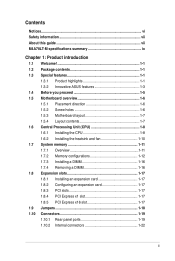
Contents Notices...vi Safety information vii About this guide vii M4A78LT-M specifications summary ix Chapter 1: Product introduction 1.1 Welcome 1-1 1.2 Package contents 1-1 1.3 Special features 1-1 1.3.1 Product highlights 1-1 1.3.2 Innovative ASUS features 1-3 1.4 Before you proceed 1-5 1.5 Motherboard overview 1-6 1.5.1 Placement direction 1-6 1.5.2 Screw holes 1-6 1.5.3 Motherboard layout 1-7 1.5.4 Layout contents 1-7 1.6 Central Processing Unit (CPU 1-8 1.6.1 Installing the CPU 1-8 1.6.2 Installing the heatsink and fan 1-10 1.7 System memory...
Contents Notices...vi Safety information vii About this guide vii M4A78LT-M specifications summary ix Chapter 1: Product introduction 1.1 Welcome 1-1 1.2 Package contents 1-1 1.3 Special features 1-1 1.3.1 Product highlights 1-1 1.3.2 Innovative ASUS features 1-3 1.4 Before you proceed 1-5 1.5 Motherboard overview 1-6 1.5.1 Placement direction 1-6 1.5.2 Screw holes 1-6 1.5.3 Motherboard layout 1-7 1.5.4 Layout contents 1-7 1.6 Central Processing Unit (CPU 1-8 1.6.1 Installing the CPU 1-8 1.6.2 Installing the heatsink and fan 1-10 1.7 System memory...

User Manual
Page 6
... Statement This device complies with Part 15 of Chemicals) regulatory framework, we published the chemical substances in our products at ASUS REACH website at http://green.asus.com/english/REACH.htm. These limits are designed to radio communications. The use of shielded cables for disposal of the ...should not be placed in municipal waste. DO NOT throw the mercury-containing button cell battery in municipal waste. DO NOT throw the motherboard in municipal waste. vi This equipment has been tested and found to enable proper reuse of the crossed out wheeled bin indicates that the...
... Statement This device complies with Part 15 of Chemicals) regulatory framework, we published the chemical substances in our products at ASUS REACH website at http://green.asus.com/english/REACH.htm. These limits are designed to radio communications. The use of shielded cables for disposal of the ...should not be placed in municipal waste. DO NOT throw the mercury-containing button cell battery in municipal waste. DO NOT throw the motherboard in municipal waste. vi This equipment has been tested and found to enable proper reuse of the crossed out wheeled bin indicates that the...

User Manual
Page 7
...in any damage, contact your dealer immediately. • To avoid short circuits, keep paper clips, screws, and staples away from the motherboard, ensure that all cables are correctly connected and the power cables are not damaged. Contact a qualified service technician or your area. ...About this guide is organized This guide contains the following parts: • Chapter 1: Product introduction This chapter describes the features of the motherboard and the new technology it supports. • Chapter 2: BIOS information This chapter tells how to change system settings through the BIOS Setup...
...in any damage, contact your dealer immediately. • To avoid short circuits, keep paper clips, screws, and staples away from the motherboard, ensure that all cables are correctly connected and the power cables are not damaged. Contact a qualified service technician or your area. ...About this guide is organized This guide contains the following parts: • Chapter 1: Product introduction This chapter describes the features of the motherboard and the new technology it supports. • Chapter 2: BIOS information This chapter tells how to change system settings through the BIOS Setup...

User Manual
Page 11
... processors with unique L3 cache and delivers better overclocking capabilities with the list below. 1.2 Package contents Check your package with less power consumption. ASUS M4A78LT-M 1-1 Before you for the following items. Motherboard Cables Accessories Application DVD Documentation ASUS M4A78LT-M motherboard 2 x Serial ATA cables 1 x Ultra DMA 133/100 cable 1 x I/O shield ASUS motherboard Support DVD User Manual If any of...
... processors with unique L3 cache and delivers better overclocking capabilities with the list below. 1.2 Package contents Check your package with less power consumption. ASUS M4A78LT-M 1-1 Before you for the following items. Motherboard Cables Accessories Application DVD Documentation ASUS M4A78LT-M motherboard 2 x Serial ATA cables 1 x Ultra DMA 133/100 cable 1 x I/O shield ASUS motherboard Support DVD User Manual If any of...
User Manual
Page 12
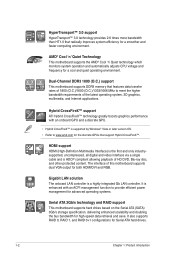
... bandwidth than HT1.0 that radically improves system efficiency for a cool and quiet operating environment. AMD® Cool 'n' Quiet Technology This motherboard supports the AMD® Cool 'n' Quiet technology which monitors system operation and automatically adjusts CPU voltage and frequency for a smoother and... management function to provide efficient power management for advanced operating systems. Serial ATA 3Gb/s technology and RAID support This motherboard supports hard drives based on the Serial ATA (SATA) 3Gb/s storage specification, delivering enhanced scalability and doubling the bus...
... bandwidth than HT1.0 that radically improves system efficiency for a cool and quiet operating environment. AMD® Cool 'n' Quiet Technology This motherboard supports the AMD® Cool 'n' Quiet technology which monitors system operation and automatically adjusts CPU voltage and frequency for a smoother and... management function to provide efficient power management for advanced operating systems. Serial ATA 3Gb/s technology and RAID support This motherboard supports hard drives based on the Serial ATA (SATA) 3Gb/s storage specification, delivering enhanced scalability and doubling the bus...

User Manual
Page 13
...SATA HDDs, USB HDDs and flash drives with at least 1.2GB free disk space. ASUS Anti-Surge Protection This special design prevents expensive devices and the motherboard from damage caused by power surges from SATA HDDs, ODDs and USB drives. When... the motherboard USB port before entering the Windows® OS. • ASUS Express Gate supports installation on the system configuration. • ASUS Express Gate supports file uploading from switching power supply (PSU). ASUS M4A78LT-M 1-3 1.3.2 Innovative ASUS features ASUS Express Gate - 0 to Inernet in Seconds ASUS Express Gate...
...SATA HDDs, USB HDDs and flash drives with at least 1.2GB free disk space. ASUS Anti-Surge Protection This special design prevents expensive devices and the motherboard from damage caused by power surges from SATA HDDs, ODDs and USB drives. When... the motherboard USB port before entering the Windows® OS. • ASUS Express Gate supports installation on the system configuration. • ASUS Express Gate supports file uploading from switching power supply (PSU). ASUS M4A78LT-M 1-3 1.3.2 Innovative ASUS features ASUS Express Gate - 0 to Inernet in Seconds ASUS Express Gate...

User Manual
Page 14
... is in real time. ASUS AI NET2 ASUS AI NET2 remotely detects the cable connection immediately after you turn on the environment. 1-4 Chapter 1: Product introduction C.P.R. (CPU Parameter Recall) The BIOS C.P.R. This is a unique ... default settings when the system hangs due to their default settings. eliminates the need to open the system chassis and clear the RTC data. Green ASUS This motherboard and its packaging comply with the ASUS vision of Hazardous Substances (RoHS).
... is in real time. ASUS AI NET2 ASUS AI NET2 remotely detects the cable connection immediately after you turn on the environment. 1-4 Chapter 1: Product introduction C.P.R. (CPU Parameter Recall) The BIOS C.P.R. This is a unique ... default settings when the system hangs due to their default settings. eliminates the need to open the system chassis and clear the RTC data. Green ASUS This motherboard and its packaging comply with the ASUS vision of Hazardous Substances (RoHS).

User Manual
Page 15
... supply and detach its power cord. Onboard LED The motherboard comes with the component. • Before you install or remove any component, switch off mode. SB_PWR M4A78LT-M ON OFF Standby Power Powered Off M4A78LT-M Onboard LED ASUS M4A78LT-M 1-5 This is a reminder that you should shut ... came with a standby power LED that lights up to the motherboard, peripherals, or components. The illustration below shows the location of the following precautions before you install motherboard components or change any motherboard settings. • Unplug the power cord from the wall socket...
... supply and detach its power cord. Onboard LED The motherboard comes with the component. • Before you install or remove any component, switch off mode. SB_PWR M4A78LT-M ON OFF Standby Power Powered Off M4A78LT-M Onboard LED ASUS M4A78LT-M 1-5 This is a reminder that you should shut ... came with a standby power LED that lights up to the motherboard, peripherals, or components. The illustration below shows the location of the following precautions before you install motherboard components or change any motherboard settings. • Unplug the power cord from the wall socket...

User Manual
Page 16
1.5 Motherboard overview 1.5.1 Placement direction When installing the motherboard, ensure that you place it into the chassis in the image below. 1.5.2 Screw holes Place eight screws into the holes indicated by circles to secure the motherboard to the rear part of the chassis. Doing so can damage the motherboard. M4A78LT-M 1-6 Chapter 1: Product introduction The edge with external ports goes to the DO NOT overtighten the screws! Place this side towards the rear of the chassis as indicated in the correct orientation.
1.5 Motherboard overview 1.5.1 Placement direction When installing the motherboard, ensure that you place it into the chassis in the image below. 1.5.2 Screw holes Place eight screws into the holes indicated by circles to secure the motherboard to the rear part of the chassis. Doing so can damage the motherboard. M4A78LT-M 1-6 Chapter 1: Product introduction The edge with external ports goes to the DO NOT overtighten the screws! Place this side towards the rear of the chassis as indicated in the correct orientation.

User Manual
Page 17
... Socket 1-8 10. DDR3 DIMM sockets 1-11 11. IDE connector (40-1 pin PRI_IDE) 1-24 14. Front panel audio connector (10-1 pin AAFP) 1-28 ASUS M4A78LT-M 1-7 Clear RTC RAM (CLRTC) 1-18 ATX12V) 2. LPT connector (26-1 pin LPT) 1-27 13. USB connectors (10-1 pin USB78, USB910, 1-27... ATA connectors (7-pin SATA1, SATA2, 1-25 SATA3, SATA4, SATA5, and SATA6) 3. Serial port connectors (10-1 pin COM1) 1-29 12. 1.5.3 Motherboard layout 12 32 24.4cm(9.6in) 4 5 KB_USB56 SPDIFO_ HDMI ATX12V CPU_FAN COM1 Super I/O LPT 6 DDR3 DIMM_A2 (64bit, 240-pin module) DDR3 DIMM_B2...
... Socket 1-8 10. DDR3 DIMM sockets 1-11 11. IDE connector (40-1 pin PRI_IDE) 1-24 14. Front panel audio connector (10-1 pin AAFP) 1-28 ASUS M4A78LT-M 1-7 Clear RTC RAM (CLRTC) 1-18 ATX12V) 2. LPT connector (26-1 pin LPT) 1-27 13. USB connectors (10-1 pin USB78, USB910, 1-27... ATA connectors (7-pin SATA1, SATA2, 1-25 SATA3, SATA4, SATA5, and SATA6) 3. Serial port connectors (10-1 pin COM1) 1-29 12. 1.5.3 Motherboard layout 12 32 24.4cm(9.6in) 4 5 KB_USB56 SPDIFO_ HDMI ATX12V CPU_FAN COM1 Super I/O LPT 6 DDR3 DIMM_A2 (64bit, 240-pin module) DDR3 DIMM_B2...

User Manual
Page 18
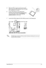
... 90°-100° angle; DO NOT force the CPU into the socket until it up to a 90°-100° angle. M4A78LT-M M4A78LT-M CPU socket AM3 2. Carefully insert the CPU into the socket to prevent bending the pins and damaging the CPU! Small triangle Gold triangle... 1-8 Chapter 1: Product introduction 1.6 Central Processing Unit (CPU) This motherboard supports AMD® Phenom™ II / Athlon™ II / Sempron™ 100 series processors. Position the CPU above the socket such ...
... 90°-100° angle; DO NOT force the CPU into the socket until it up to a 90°-100° angle. M4A78LT-M M4A78LT-M CPU socket AM3 2. Carefully insert the CPU into the socket to prevent bending the pins and damaging the CPU! Small triangle Gold triangle... 1-8 Chapter 1: Product introduction 1.6 Central Processing Unit (CPU) This motherboard supports AMD® Phenom™ II / Athlon™ II / Sempron™ 100 series processors. Position the CPU above the socket such ...
User Manual
Page 19
... PWR CPU FAN IN CPU FAN PWM ASUS M4A78LT-M 1-9 5. Hardware monitoring errors can also refer to plug this connector. Connect the CPU fan cable to the CPU_FAN connector on the side tab to indicate that comes with the heatsink package. The lever clicks on the motherboard. CPU_FAN M4A78LT-M M4A78LT-M CPU fan connector DO NOT forget...
... PWR CPU FAN IN CPU FAN PWM ASUS M4A78LT-M 1-9 5. Hardware monitoring errors can also refer to plug this connector. Connect the CPU fan cable to the CPU_FAN connector on the side tab to indicate that comes with the heatsink package. The lever clicks on the motherboard. CPU_FAN M4A78LT-M M4A78LT-M CPU fan connector DO NOT forget...
User Manual
Page 20
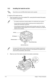
... section do not have to remove the retention module base when installing the CPU or installing other motherboard components. • If you use only AMD-certified heatsink and fan assembly. Place the heatsink on the motherboard upon purchase. • You do not match the CPU documentation, follow the latter. 2. Attach one end...
... section do not have to remove the retention module base when installing the CPU or installing other motherboard components. • If you use only AMD-certified heatsink and fan assembly. Place the heatsink on the motherboard upon purchase. • You do not match the CPU documentation, follow the latter. 2. Attach one end...

User Manual
Page 21
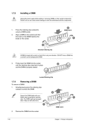
...the DDR3 DIMM sockets: DIMM_A2 DIMM_B2 DIMM_A1 DIMM_B1 Channel Channel A Channel B Sockets DIMM_A1 and DIMM_A2 DIMM_B1 and DIMM_B2 M4A78LT-M M4A78LT-M 240-pin DDR3 DIMM sockets ASUS M4A78LT-M 1-11 A clicking sound denotes that the fan and heatsink assembly perfectly fits the retention mechanism module base, otherwise...! The figure illustrates the location of the retention bracket to plug this connector. 1.7 System memory 1.7.1 Overview The motherboard comes with four Double Data Rate 3 (DDR3) Dual Inline Memory Modules (DIMM) sockets. 3. Ensure that the retention bracket is in...
...the DDR3 DIMM sockets: DIMM_A2 DIMM_B2 DIMM_A1 DIMM_B1 Channel Channel A Channel B Sockets DIMM_A1 and DIMM_A2 DIMM_B1 and DIMM_B2 M4A78LT-M M4A78LT-M 240-pin DDR3 DIMM sockets ASUS M4A78LT-M 1-11 A clicking sound denotes that the fan and heatsink assembly perfectly fits the retention mechanism module base, otherwise...! The figure illustrates the location of the retention bracket to plug this connector. 1.7 System memory 1.7.1 Overview The motherboard comes with four Double Data Rate 3 (DDR3) Dual Inline Memory Modules (DIMM) sockets. 3. Ensure that the retention bracket is in...

User Manual
Page 22
...-bit Windows® OS, when you do any of memory, we recommend that you install 4GB or more memory on the motherboard. • This motherboard does not support DIMMs made up of the lower-sized channel for the OS can be about 3GB or less. For effective ...;W�i�nd�o�w��s® OS if you want to the memory address limitation on the motherboard, the actual usable memory for the dual-channel configuration. M4A78LT-M Motherboard Qualified Vendors Lists (QVL) DDR3-1866(O.C.)MHz capability Vendor Part No. Size SS/ Chip Chip NO. The system...
...-bit Windows® OS, when you do any of memory, we recommend that you install 4GB or more memory on the motherboard. • This motherboard does not support DIMMs made up of the lower-sized channel for the OS can be about 3GB or less. For effective ...;W�i�nd�o�w��s® OS if you want to the memory address limitation on the motherboard, the actual usable memory for the dual-channel configuration. M4A78LT-M Motherboard Qualified Vendors Lists (QVL) DDR3-1866(O.C.)MHz capability Vendor Part No. Size SS/ Chip Chip NO. The system...
User Manual
Page 26
... into a socket to unlock a DIMM socket. 2. Remove the DIMM from the socket. 1-16 Chapter 1: Product introduction Simultaneously press the retaining clips outward to both the motherboard and the components. 1. Failure to do so can cause severe damage to unlock the DIMM. 2 Support the DIMM lightly with your fingers when pressing the...
... into a socket to unlock a DIMM socket. 2. Remove the DIMM from the socket. 1-16 Chapter 1: Product introduction Simultaneously press the retaining clips outward to both the motherboard and the components. 1. Failure to do so can cause severe damage to unlock the DIMM. 2 Support the DIMM lightly with your fingers when pressing the...

User Manual
Page 27
... slot that the cards do so may cause you may need IRQ assignments. Secure the card to use . 4. Turn on the slot. 5. ASUS M4A78LT-M 1-17 Align the card connector with the PCI Express specifications. When using PCI cards on BIOS setup. 2. Keep the screw for information on ...an IRQ to install expansion cards. Unplug the power cord before adding or removing expansion cards. Remove the system unit cover (if your motherboard is completely seated on the system and change the necessary BIOS settings, if any. 1.8 Expansion slots In the future, you physical injury and...
... slot that the cards do so may cause you may need IRQ assignments. Secure the card to use . 4. Turn on the slot. 5. ASUS M4A78LT-M 1-17 Align the card connector with the PCI Express specifications. When using PCI cards on BIOS setup. 2. Keep the screw for information on ...an IRQ to install expansion cards. Unplug the power cord before adding or removing expansion cards. Remove the system unit cover (if your motherboard is completely seated on the system and change the necessary BIOS settings, if any. 1.8 Expansion slots In the future, you physical injury and...

User Manual
Page 30
... whether the following dual display outputs are supported for any DVI-D compatible device and is HDCP compliant allowing playback of sound playback is for your motherboard: Dual display outputs DVI + D-Sub DVI + HDMI HDMI + D-Sub Supported • • Not supported • • During POST, only the monitor connected to configure the...
... whether the following dual display outputs are supported for any DVI-D compatible device and is HDCP compliant allowing playback of sound playback is for your motherboard: Dual display outputs DVI + D-Sub DVI + HDMI HDMI + D-Sub Supported • • Not supported • • During POST, only the monitor connected to configure the...

User Manual
Page 34
Connect the blue connector to the motherboard's IDE connector, then select one of device(s) - M4A78LT-M IDE connector 1-24 Chapter 1: Product introduction PRI_IDE PIN1 M4A78LT-M NOTE:Orient the red markings on each Ultra DMA 133/100 signal cable: blue, black, and gray. If any device jumper is for Ultra DMA ...
Connect the blue connector to the motherboard's IDE connector, then select one of device(s) - M4A78LT-M IDE connector 1-24 Chapter 1: Product introduction PRI_IDE PIN1 M4A78LT-M NOTE:Orient the red markings on each Ultra DMA 133/100 signal cable: blue, black, and gray. If any device jumper is for Ultra DMA ...


