User Manual
Page 3
... Safety information vii About this guide viii M4A78L-M specifications summary x Chapter 1: Product introduction 1.1 Welcome 1-1 1.2 Package contents 1-1 1.3 Special features 1-1 1.3.1 Product highlights 1-1 1.3.2 Innovative ASUS features 1-3 1.4 Before you proceed 1-5 1.5 Motherboard overview 1-6 1.5.1 Placement direction 1-6 1.5.2 Screw holes 1-6 1.5.3 Motherboard layout 1-7 1.5.4 Layout contents 1-7 1.6 Central Processing Unit (CPU 1-8 1.6.1 Installing the CPU 1-8 1.6.2 Installing the heatsink and fan 1-10 1.7 System memory 1-11 1.7.1 Overview 1-11 1.7.2 Memory...
... Safety information vii About this guide viii M4A78L-M specifications summary x Chapter 1: Product introduction 1.1 Welcome 1-1 1.2 Package contents 1-1 1.3 Special features 1-1 1.3.1 Product highlights 1-1 1.3.2 Innovative ASUS features 1-3 1.4 Before you proceed 1-5 1.5 Motherboard overview 1-6 1.5.1 Placement direction 1-6 1.5.2 Screw holes 1-6 1.5.3 Motherboard layout 1-7 1.5.4 Layout contents 1-7 1.6 Central Processing Unit (CPU 1-8 1.6.1 Installing the CPU 1-8 1.6.2 Installing the heatsink and fan 1-10 1.7 System memory 1-11 1.7.1 Overview 1-11 1.7.2 Memory...
User Manual
Page 11
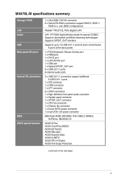
... 6 USB 2.0/1.1 ports 1 x IDE connector 1 x COM connector 1 x LPT connector 6 x SATA connectors 1 x High definition front panel audio connector 1 x System panel connector 1 x S/PDIF_OUT connector 1 x CPU fan connector 1 x Chassis fan connector 1 x 24-pin EATX power connector 1 x 4-pin ATX 12V power connector 8Mb Flash ROM, AMI BIOS, PnP, DMI2.0, WfM2.0, ACPI2.0a, SM BIOS 2.5 ASUS Q-Fan ASUS CrashFree BIOS3 ASUS EZ Flash2 ASUS MyLogo2 ASUS Express Gate ASUS AI NET2 ASUS EPU-4 Engine ASUS Anti-Surge Protection (continued...
... 6 USB 2.0/1.1 ports 1 x IDE connector 1 x COM connector 1 x LPT connector 6 x SATA connectors 1 x High definition front panel audio connector 1 x System panel connector 1 x S/PDIF_OUT connector 1 x CPU fan connector 1 x Chassis fan connector 1 x 24-pin EATX power connector 1 x 4-pin ATX 12V power connector 8Mb Flash ROM, AMI BIOS, PnP, DMI2.0, WfM2.0, ACPI2.0a, SM BIOS 2.5 ASUS Q-Fan ASUS CrashFree BIOS3 ASUS EZ Flash2 ASUS MyLogo2 ASUS Express Gate ASUS AI NET2 ASUS EPU-4 Engine ASUS Anti-Surge Protection (continued...
User Manual
Page 19
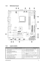
... Page 1-27 1-5 1-26 1-28 1-29 1-23 1-18 ASUS M4A78L-M 1-7 CPU Socket AM2+ 3. IDE connector (40-1 pin PRI_IDE) 8. Front panel audio connector (10-1 pin AAFP) 1-25 15. Serial port connector (10-1 pin COM1) 6. System panel connector (20-8 pin PANEL) 10. Clear RTC RAM (3-pin CLRTC) Page 1-24 1-8 1-23 Connectors/Jumpers/Slots/LED 9. 1.5.3 Motherboard layout 1 24 3 4 5 22.4cm(8.8in) KB_USB56...
... Page 1-27 1-5 1-26 1-28 1-29 1-23 1-18 ASUS M4A78L-M 1-7 CPU Socket AM2+ 3. IDE connector (40-1 pin PRI_IDE) 8. Front panel audio connector (10-1 pin AAFP) 1-25 15. Serial port connector (10-1 pin COM1) 6. System panel connector (20-8 pin PANEL) 10. Clear RTC RAM (3-pin CLRTC) Page 1-24 1-8 1-23 Connectors/Jumpers/Slots/LED 9. 1.5.3 Motherboard layout 1 24 3 4 5 22.4cm(8.8in) KB_USB56...
User Manual
Page 21
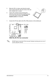
... comes with the heatsink package. The lever clicks on the motherboard. When the CPU is locked. 6. CPU_FAN M4A78L-M M4A78L-M CPU fan connector DO NOT forget to section 1.6.2 Installing heatsink and fan for instructions. 7. 5. Hardware monitoring errors can also refer to connect the CPU fan connector! Install a CPU heatsink and fan following the instructions that it is in place, push...
... comes with the heatsink package. The lever clicks on the motherboard. When the CPU is locked. 6. CPU_FAN M4A78L-M M4A78L-M CPU fan connector DO NOT forget to section 1.6.2 Installing heatsink and fan for instructions. 7. 5. Hardware monitoring errors can also refer to connect the CPU fan connector! Install a CPU heatsink and fan following the instructions that it is in place, push...
User Manual
Page 23
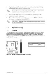
... end of the DDR2 DIMM sockets: DIMM_A1 DIMM_B1 Channel Channel A Channel B M4A78L-M M4A78L-M 240-pin DDR2 DIMM sockets Sockets DIMM_A1 DIMM_B1 ASUS M4A78L-M 1-11 When the fan and heatsink assembly is in place, connect the CPU fan cable to plug this connector. 1.7 System memory 1.7.1 Overview The motherboard comes with two Double Data Rate 2 (DDR2) Dual Inline Memory Modules...
... end of the DDR2 DIMM sockets: DIMM_A1 DIMM_B1 Channel Channel A Channel B M4A78L-M M4A78L-M 240-pin DDR2 DIMM sockets Sockets DIMM_A1 DIMM_B1 ASUS M4A78L-M 1-11 When the fan and heatsink assembly is in place, connect the CPU fan cable to plug this connector. 1.7 System memory 1.7.1 Overview The motherboard comes with two Double Data Rate 2 (DDR2) Dual Inline Memory Modules...

User Manual
Page 35
... Connect the fan cables to the fan connectors on the motherboard, ensuring that you want to connect a high definition front panel audio module to this connector. Front panel audio connector (10-1 pin AAFP) This connector is purchased ...fan connectors (4-pin CPU_FAN and 3-pin CHA_FAN) The fan connectors support cooling fans of 350mA~740mA (8.88W max.) or a total of the front panel audio I /O module that supports either High Definition Audio or AC`97 audio standard. 2. CHA_FAN CPU_FAN Rotation +12V GND CPU FAN PWM CPU FAN IN CPU FAN PWR GND M4A78L-M M4A78L-M fan connectors ASUS M4A78L...
... Connect the fan cables to the fan connectors on the motherboard, ensuring that you want to connect a high definition front panel audio module to this connector. Front panel audio connector (10-1 pin AAFP) This connector is purchased ...fan connectors (4-pin CPU_FAN and 3-pin CHA_FAN) The fan connectors support cooling fans of 350mA~740mA (8.88W max.) or a total of the front panel audio I /O module that supports either High Definition Audio or AC`97 audio standard. 2. CHA_FAN CPU_FAN Rotation +12V GND CPU FAN PWM CPU FAN IN CPU FAN PWR GND M4A78L-M M4A78L-M fan connectors ASUS M4A78L...

User Manual
Page 36
... PIN 1 M4A78L-M ATX power connectors GND +5 Volts +5 Volts +5 Volts -5 Volts GND GND GND PSON# GND -12 Volts +3 Volts • We recommend that you use a PSU with higher power output when configuring a system with more power-consuming devices or when you intend to the fan connectors. The system may become unstable or may damage the motherboard components...
... PIN 1 M4A78L-M ATX power connectors GND +5 Volts +5 Volts +5 Volts -5 Volts GND GND GND PSON# GND -12 Volts +3 Volts • We recommend that you use a PSU with higher power output when configuring a system with more power-consuming devices or when you intend to the fan connectors. The system may become unstable or may damage the motherboard components...


