User Manual
Page 13
...; 3.0-based system bus. Before you for the following items. Motherboard Cables Accessories Application DVD Documentation ASUS M4A78L-M LE motherboard 2 x Serial ATA cables 1 x Ultra DMA 133/100 cable 1 x I/O shield ASUS motherboard Support DVD User Manual If any of ASUS quality motherboards! ASUS M4A78L-M LE 1-1 Chapter 1 Product introduction 1.1 Welcome! This motherboard also supports AMD® CPUs in your ... on it another standout in the long line of the above items is damaged or missing, contact your motherboard package for buying an ASUS® M4A78L-M LE motherboard!
...; 3.0-based system bus. Before you for the following items. Motherboard Cables Accessories Application DVD Documentation ASUS M4A78L-M LE motherboard 2 x Serial ATA cables 1 x Ultra DMA 133/100 cable 1 x I/O shield ASUS motherboard Support DVD User Manual If any of ASUS quality motherboards! ASUS M4A78L-M LE 1-1 Chapter 1 Product introduction 1.1 Welcome! This motherboard also supports AMD® CPUs in your ... on it another standout in the long line of the above items is damaged or missing, contact your motherboard package for buying an ASUS® M4A78L-M LE motherboard!

User Manual
Page 15
... the easy setup, Turbo Key boosts performances without entering the Windows® OS. • ASUS Express Gate supports installation on the system configuration. • ASUS Express Gate supports file uploading from SATA HDDs, ODDs and USB drives. ASUS M4A78L-M LE 1-3 Gigabit LAN solution The onboard LAN controller is enhanced with an ACPI management function to...
... the easy setup, Turbo Key boosts performances without entering the Windows® OS. • ASUS Express Gate supports installation on the system configuration. • ASUS Express Gate supports file uploading from SATA HDDs, ODDs and USB drives. ASUS M4A78L-M LE 1-3 Gigabit LAN solution The onboard LAN controller is enhanced with an ACPI management function to...
User Manual
Page 17
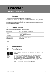
... cause severe damage to indicate that the system is a reminder that lights up to the motherboard, peripherals, or components. SB_PWR M4A78L-M LE ON OFF Standby Power Powered Off M4A78L-M LE Onboard power LED ASUS M4A78L-M LE 1-5 P5KPL-AM/PS • Hold components by the edges to avoid touching the ICs on them due to avoid damaging them...
... cause severe damage to indicate that the system is a reminder that lights up to the motherboard, peripherals, or components. SB_PWR M4A78L-M LE ON OFF Standby Power Powered Off M4A78L-M LE Onboard power LED ASUS M4A78L-M LE 1-5 P5KPL-AM/PS • Hold components by the edges to avoid touching the ICs on them due to avoid damaging them...

User Manual
Page 19
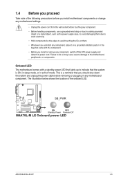
....4cm(9.6in) LPT VGA 16 USB34 USBPW1-4 LAN1_USB12 Super I/O CHA_FAN CPU_FAN AUDIO AMD® 780L ICS9LPRS485 PCIe Gb LAN VT1708S AAFP PCIEX1_1 SPDIF_OUT PRI_IDE PCIEX16 M4A78L-M LE PCI1 PCI2 AMD® SB710 Lithium Cell CMOS Power SB_PWR SPEAKER SATA1 SATA4 SATA2 SATA5 SATA3 SATA6 8Mb BIOS CLRTC F_PANEL USBPW5-10 USB78 USB910... panel connector (10-1 pin F_PANEL) 1-11 14. CPU Socket AM2+ 6. PCIe x16 / PCIe x1 / PCI slots Page 1-28 1-19 1-25 1-27 1-26 1-28 1-22 1-18 ASUS M4A78L-M LE 1-7
....4cm(9.6in) LPT VGA 16 USB34 USBPW1-4 LAN1_USB12 Super I/O CHA_FAN CPU_FAN AUDIO AMD® 780L ICS9LPRS485 PCIe Gb LAN VT1708S AAFP PCIEX1_1 SPDIF_OUT PRI_IDE PCIEX16 M4A78L-M LE PCI1 PCI2 AMD® SB710 Lithium Cell CMOS Power SB_PWR SPEAKER SATA1 SATA4 SATA2 SATA5 SATA3 SATA6 8Mb BIOS CLRTC F_PANEL USBPW5-10 USB78 USB910... panel connector (10-1 pin F_PANEL) 1-11 14. CPU Socket AM2+ 6. PCIe x16 / PCIe x1 / PCI slots Page 1-28 1-19 1-25 1-27 1-26 1-28 1-22 1-18 ASUS M4A78L-M LE 1-7

User Manual
Page 21
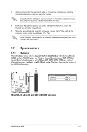
... CPU FAN PWM CPU FAN IN CPU FAN PWR GND M4A78L-M LE CPU fan connector DO NOT forget to secure the CPU. Hardware monitoring errors can also refer to section 1.6.2 Installing heatsink and fan for instructions. 7. 5. Connect ... locked. 6. Install a CPU heatsink and fan following the instructions that it is in place, push down the socket lever to connect the CPU fan connector! ASUS M4A78L-M LE 1-9
... CPU FAN PWM CPU FAN IN CPU FAN PWR GND M4A78L-M LE CPU fan connector DO NOT forget to secure the CPU. Hardware monitoring errors can also refer to section 1.6.2 Installing heatsink and fan for instructions. 7. 5. Connect ... locked. 6. Install a CPU heatsink and fan following the instructions that it is in place, push down the socket lever to connect the CPU fan connector! ASUS M4A78L-M LE 1-9
User Manual
Page 23
... cannot snap the retention bracket in place. 4. Align the other end of the DDR2 DIMM sockets: DIMM_A1 DIMM_B1 Channel Channel A Channel B M4A78L-M LE M4A78L-M LE 240-pin DDR2 DIMM sockets Sockets DIMM_A1 DIMM_B1 ASUS M4A78L-M LE 1-11 When the fan and heatsink assembly is in place, connect the CPU fan cable to plug this connector. 1.7 System memory...
... cannot snap the retention bracket in place. 4. Align the other end of the DDR2 DIMM sockets: DIMM_A1 DIMM_B1 Channel Channel A Channel B M4A78L-M LE M4A78L-M LE 240-pin DDR2 DIMM sockets Sockets DIMM_A1 DIMM_B1 ASUS M4A78L-M LE 1-11 When the fan and heatsink assembly is in place, connect the CPU fan cable to plug this connector. 1.7 System memory...
User Manual
Page 25
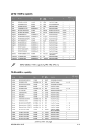
...-Sink Package Heat-Sink Package Heat-Sink Package Heat-Sink Package SN:8151030036642 Heat-Sink Package Heat-Sink Package Heat-Sink Package Heat-Sink Package ASUS M4A78L-M LE (continued on the next page) CL 4-4-4-12 4-4-4-12 5 4 5 5 5 4-4-4-12 4-4-4-12 4-4-4-12 5-5-5-15 4 5 4 5 DIMM support A* B* • • • • • • • • • • •...
...-Sink Package Heat-Sink Package Heat-Sink Package Heat-Sink Package SN:8151030036642 Heat-Sink Package Heat-Sink Package Heat-Sink Package Heat-Sink Package ASUS M4A78L-M LE (continued on the next page) CL 4-4-4-12 4-4-4-12 5 4 5 5 5 4-4-4-12 4-4-4-12 4-4-4-12 5-5-5-15 4 5 4 5 DIMM support A* B* • • • • • • • • • • •...

User Manual
Page 27
... TAKEMS UMAX UMAX VDATA VDATA MDT 512MB MDT 1024MB TMS51B264C081-805EP TMS1GB264D082-805EE TMS1GB264C081-804EE TMS1GB264C081-805EP TMS2GB264D081-805KE D48001GP3-63BJU D48002GP0-73BCU M2XSSKG3147C1L1C5Z M2XHYKH3J47CC01E5Z ASUS M4A78L-M LE Size 1024MB 2048MB 2048MB 2048MB 2048MB 2048MB 2048MB 512MB 1024MB 1024MB 1024MB 1024MB 1024MB 2048MB 2048MB 4096MB 1024MB 512MB 1024MB 1024MB 1024MB 1024MB 1024MB 2048MB...
... TAKEMS UMAX UMAX VDATA VDATA MDT 512MB MDT 1024MB TMS51B264C081-805EP TMS1GB264D082-805EE TMS1GB264C081-804EE TMS1GB264C081-805EP TMS2GB264D081-805KE D48001GP3-63BJU D48002GP0-73BCU M2XSSKG3147C1L1C5Z M2XHYKH3J47CC01E5Z ASUS M4A78L-M LE Size 1024MB 2048MB 2048MB 2048MB 2048MB 2048MB 2048MB 512MB 1024MB 1024MB 1024MB 1024MB 1024MB 2048MB 2048MB 4096MB 1024MB 512MB 1024MB 1024MB 1024MB 1024MB 1024MB 2048MB...
User Manual
Page 29
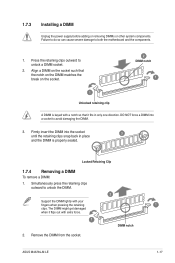
... notch 1 1 Unlocked retaining clip A DIMM is properly seated. Locked Retaining Clip 1.7.4 Removing a DIMM To remove a DIMM: 1. Press the retaining clips outward to unlock the DIMM. ASUS M4A78L-M LE 1 1-17
... notch 1 1 Unlocked retaining clip A DIMM is properly seated. Locked Retaining Clip 1.7.4 Removing a DIMM To remove a DIMM: 1. Press the retaining clips outward to unlock the DIMM. ASUS M4A78L-M LE 1 1-17
User Manual
Page 31
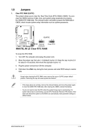
1.9 Jumpers 1. Move the jumper cap from pins 1-2 (default) to overclocking, use the CPU Parameter Recall (C.P.R) feature. ASUS M4A78L-M LE 1-19 CLRTC 12 23 M4A78L-M LE Normal (Default) Clear RTC M4A78L-M LE Clear RTC RAM To erase the RTC RAM: 1. Turn OFF the computer and unplug the power cord. 2. For system failure due to pins 2-3. The onboard ...
1.9 Jumpers 1. Move the jumper cap from pins 1-2 (default) to overclocking, use the CPU Parameter Recall (C.P.R) feature. ASUS M4A78L-M LE 1-19 CLRTC 12 23 M4A78L-M LE Normal (Default) Clear RTC M4A78L-M LE Clear RTC RAM To erase the RTC RAM: 1. Turn OFF the computer and unplug the power cord. 2. For system failure due to pins 2-3. The onboard ...

User Manual
Page 33
... 2-channel Line In Line Out Mic In 4-channel Rear Speaker Out Front Speaker Out Mic In 6-channel Rear Speaker Out Front Speaker Out Bass/Center ASUS M4A78L-M LE 1-21 This port is for the function of this port becomes Front Speaker Out. 6. Microphone port (pink). This port allows Gigabit connection to a microphone. This...
... 2-channel Line In Line Out Mic In 4-channel Rear Speaker Out Front Speaker Out Mic In 6-channel Rear Speaker Out Front Speaker Out Bass/Center ASUS M4A78L-M LE 1-21 This port is for the function of this port becomes Front Speaker Out. 6. Microphone port (pink). This port allows Gigabit connection to a microphone. This...

User Manual
Page 35
ASUS M4A78L-M LE 1-23 The system may become unstable or may not boot up if the...become unstable or may not boot up . • We recommend that the 20-pin power plug can provide at http://support.asus. ATX12V EATXPWR M4A78L-M LE +12V DC +12V DC PIN 1 GND +3 Volts GND +12 Volts +12 Volts +5V Standby Power OK GND +5 ... GND +3 Volts +3 Volts PIN 1 GND +5 Volts +5 Volts +5 Volts -5 Volts GND GND GND PSON# GND -12 Volts +3 Volts M4A78L-M LE ATX power connectors • We recommend that the PSU has a minimum power rating of 300W power rating. 2. ATX power connectors (24-pin ...
ASUS M4A78L-M LE 1-23 The system may become unstable or may not boot up if the...become unstable or may not boot up . • We recommend that the 20-pin power plug can provide at http://support.asus. ATX12V EATXPWR M4A78L-M LE +12V DC +12V DC PIN 1 GND +3 Volts GND +12 Volts +12 Volts +5V Standby Power OK GND +5 ... GND +3 Volts +3 Volts PIN 1 GND +5 Volts +5 Volts +5 Volts -5 Volts GND GND GND PSON# GND -12 Volts +3 Volts M4A78L-M LE ATX power connectors • We recommend that the PSU has a minimum power rating of 300W power rating. 2. ATX power connectors (24-pin ...

User Manual
Page 37
... RSATA_TXP5 GND GND RSATA_RXN2 RSATA_RXP2 GND RSATA_TXN2 RSATA_TXP2 GND SATA2 SATA5 GND RSATA_RXN6 RSATA_RXP6 GND RSATA_TXN6 RSATA_TXP6 GND GND RSATA_RXN3 RSATA_RXP3 GND RSATA_TXN3 RSATA_TXP3 GND M4A78L-M LE SATA3 M4A78L-M LE SATA connectors SATA6 • Install the Windows® XP Service Pack 1 or later versions before using Serial ATA. • If you can create a RAID... ATA connectors (7-pin SATA1 - 6) These connectors are for the Serial ATA signal cables for details. • The motherboard does not provide a floppy disk drive connector. ASUS M4A78L-M LE 1-25
... RSATA_TXP5 GND GND RSATA_RXN2 RSATA_RXP2 GND RSATA_TXN2 RSATA_TXP2 GND SATA2 SATA5 GND RSATA_RXN6 RSATA_RXP6 GND RSATA_TXN6 RSATA_TXP6 GND GND RSATA_RXN3 RSATA_RXP3 GND RSATA_TXN3 RSATA_TXP3 GND M4A78L-M LE SATA3 M4A78L-M LE SATA connectors SATA6 • Install the Windows® XP Service Pack 1 or later versions before using Serial ATA. • If you can create a RAID... ATA connectors (7-pin SATA1 - 6) These connectors are for the Serial ATA signal cables for details. • The motherboard does not provide a floppy disk drive connector. ASUS M4A78L-M LE 1-25
User Manual
Page 39
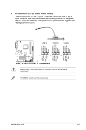
These USB connectors comply with USB 2.0 specification that supports up to the USB connectors. ASUS M4A78L-M LE 1-27 The USB 2.0 module is purchased separately. Doing so will damage the motherboard! 6. USB+5V USB_P8USB_P8+ GND NC USB+5V USB_P10USB_P10+ GND... NC USB+5V USB_P6USB_P6+ GND NC USB+5V USB_P7USB_P7+ GND USB+5V USB_P9USB_P9+ GND USB+5V USB_P5USB_P5+ GND USB78 USB910 USB56 M4A78L-M LE PIN 1 PIN 1 PIN 1 M4A78L-M LE USB2.0 connectors Never connect a 1394 cable to 480Mbps connection speed. Connect the USB module cable to any of these connectors, then install...
These USB connectors comply with USB 2.0 specification that supports up to the USB connectors. ASUS M4A78L-M LE 1-27 The USB 2.0 module is purchased separately. Doing so will damage the motherboard! 6. USB+5V USB_P8USB_P8+ GND NC USB+5V USB_P10USB_P10+ GND... NC USB+5V USB_P6USB_P6+ GND NC USB+5V USB_P7USB_P7+ GND USB+5V USB_P9USB_P9+ GND USB+5V USB_P5USB_P5+ GND USB78 USB910 USB56 M4A78L-M LE PIN 1 PIN 1 PIN 1 M4A78L-M LE USB2.0 connectors Never connect a 1394 cable to 480Mbps connection speed. Connect the USB module cable to any of these connectors, then install...
User Manual
Page 41
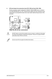
... FAN PWM CPU FAN IN CPU FAN PWR GND M4A78L-M LE fan connectors DO NOT forget to connect the fan cables to the fan connectors on the fan connectors. These are not jumpers! DO NOT place ... black wire of each cable matches the ground pin of 1A~2.22A (26.64W max.) at +12V. Only the 4-pin CPU fan supports the ASUS Q-Fan feature. ASUS M4A78L-M LE 1-29 9. Insufficient air flow inside the system may damage the motherboard components. Connect the fan cables to the fan connectors. CPU and chassis fan...
... FAN PWM CPU FAN IN CPU FAN PWR GND M4A78L-M LE fan connectors DO NOT forget to connect the fan cables to the fan connectors on the fan connectors. These are not jumpers! DO NOT place ... black wire of each cable matches the ground pin of 1A~2.22A (26.64W max.) at +12V. Only the 4-pin CPU fan supports the ASUS Q-Fan feature. ASUS M4A78L-M LE 1-29 9. Insufficient air flow inside the system may damage the motherboard components. Connect the fan cables to the fan connectors. CPU and chassis fan...
User Manual
Page 43
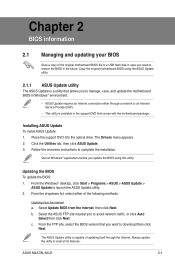
... a utility that allows you to manage, save, and update the motherboard BIOS in Windows® environment. • ASUS Update requires an Internet connection either of the following methods: Updating from the Internet, then click Next. From the FTP... to download then click Next. Click the Utilities tab, then click ASUS Update. 3. Place the support DVD into the optical drive. ASUS M4A78L-M LE 2-1 Follow the onscreen instructions to launch the ASUS Update utility. 2. Installing ASUS Update To install ASUS Update: 1. Select Update BIOS from the Internet a. Updating the BIOS...
... a utility that allows you to manage, save, and update the motherboard BIOS in Windows® environment. • ASUS Update requires an Internet connection either of the following methods: Updating from the Internet, then click Next. From the FTP... to download then click Next. Click the Utilities tab, then click ASUS Update. 3. Place the support DVD into the optical drive. ASUS M4A78L-M LE 2-1 Follow the onscreen instructions to launch the ASUS Update utility. 2. Installing ASUS Update To install ASUS Update: 1. Select Update BIOS from the Internet a. Updating the BIOS...

User Manual
Page 45
... support DVD or a removable device that allows you to the optical drive or the removable device that ASUS CrashFree BIOS supports vary with motherboard models. ASUS M4A78L-M LE 2-3 Insert the support DVD to restore the BIOS file when it fails or gets corrupted during the ... this utility. The utility automatically checks the devices for details. You can cause system boot failure! Turn on again. 2.1.3 ASUS CrashFree BIOS utility The ASUS CrashFree BIOS is found, the utility reads it and starts flashing the corrupted BIOS file. 4. Refer to ensure system compatibility...
... support DVD or a removable device that allows you to the optical drive or the removable device that ASUS CrashFree BIOS supports vary with motherboard models. ASUS M4A78L-M LE 2-3 Insert the support DVD to restore the BIOS file when it fails or gets corrupted during the ... this utility. The utility automatically checks the devices for details. You can cause system boot failure! Turn on again. 2.1.3 ASUS CrashFree BIOS utility The ASUS CrashFree BIOS is found, the utility reads it and starts flashing the corrupted BIOS file. 4. Refer to ensure system compatibility...
User Manual
Page 47
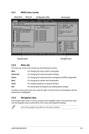
... and change the settings. Some of a menu screen are the navigation keys for special functions Exit For selecting the exit options and loading default settings. ASUS M4A78L-M LE 2-5 To select an item on the menu bar, press the right or left arrow key on top of the screen has the following main items...
... and change the settings. Some of a menu screen are the navigation keys for special functions Exit For selecting the exit options and loading default settings. ASUS M4A78L-M LE 2-5 To select an item on the menu bar, press the right or left arrow key on top of the screen has the following main items...

User Manual
Page 49
... BIOS automatically detects the values opposite the dimmed items (Device, Vendor, Size, LBA Mode, Block Mode, PIO Mode, Async DMA, Ultra DMA, and SMART monitoring). ASUS M4A78L-M LE 2-7 Type [Auto] Selects the type of the appropriate IDE/SATA device type. Setting this item to section 2.2.1 BIOS menu screen for each IDE/SATA device...
... BIOS automatically detects the values opposite the dimmed items (Device, Vendor, Size, LBA Mode, Block Mode, PIO Mode, Async DMA, Ultra DMA, and SMART monitoring). ASUS M4A78L-M LE 2-7 Type [Auto] Selects the type of the appropriate IDE/SATA device type. Setting this item to section 2.2.1 BIOS menu screen for each IDE/SATA device...

User Manual
Page 51
... Information Displays the auto-detected BIOS information. CPU OverClocking [Auto] Selects the CPU overclocking options to malfunction. Configuration options: [Auto] [Manual] [Overclock Profile] [Test Mode] ASUS M4A78L-M LE 2-9 Processor Displays the auto-detected CPU specification. System Memory Displays the auto-detected system memory. 2.4 Advanced menu The Advanced menu items allow you an overview...
... Information Displays the auto-detected BIOS information. CPU OverClocking [Auto] Selects the CPU overclocking options to malfunction. Configuration options: [Auto] [Manual] [Overclock Profile] [Test Mode] ASUS M4A78L-M LE 2-9 Processor Displays the auto-detected CPU specification. System Memory Displays the auto-detected system memory. 2.4 Advanced menu The Advanced menu items allow you an overview...


