
User Manual
Page 1
Motherboard
Motherboard

User Manual
Page 1
M4A78 PRO Motherboard
M4A78 PRO Motherboard
User Manual
Page 3
Contents Contents...iii Notices...vi Safety information vii About this guide vii M4A78 PRO specifications summary ix Chapter 1 Product introduction 1.1 Welcome 1-1 1.2 Package contents 1-1 1.3 Special features 1-1 1.3.1 Product highlights 1-1 1.3.2 Innovative ASUS features 1-2 1.4 Before you proceed 1-4 1.5 Motherboard overview 1-5 1.5.1 Placement direction 1-5 1.5.2 Screw holes 1-5 1.5.3 Motherboard layout 1-6 1.5.4 Layout contents 1-6 1.6 Central Processing Unit (CPU 1-7 1.6.1 Installing the CPU 1-7 1.6.2 Installing the heatsink and fan 1-8 1.7 System...
Contents Contents...iii Notices...vi Safety information vii About this guide vii M4A78 PRO specifications summary ix Chapter 1 Product introduction 1.1 Welcome 1-1 1.2 Package contents 1-1 1.3 Special features 1-1 1.3.1 Product highlights 1-1 1.3.2 Innovative ASUS features 1-2 1.4 Before you proceed 1-4 1.5 Motherboard overview 1-5 1.5.1 Placement direction 1-5 1.5.2 Screw holes 1-5 1.5.3 Motherboard layout 1-6 1.5.4 Layout contents 1-6 1.6 Central Processing Unit (CPU 1-7 1.6.1 Installing the CPU 1-7 1.6.2 Installing the heatsink and fan 1-8 1.7 System...
User Manual
Page 6
... the graphics card is connected. • Consult the dealer or an experienced radio/TV technician for connection of parts and recycling. DO NOT throw the motherboard in municipal waste. This equipment has been tested and found to comply with FCC regulations. This equipment generates, uses and can be determined by one...
... the graphics card is connected. • Consult the dealer or an experienced radio/TV technician for connection of parts and recycling. DO NOT throw the motherboard in municipal waste. This equipment has been tested and found to comply with FCC regulations. This equipment generates, uses and can be determined by one...
User Manual
Page 7
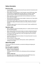
...• Ensure that came with the product, contact a qualified service technician or your retailer. Operation safety • Before installing the motherboard and adding devices on a stable surface. • If you encounter technical problems with the package. • Before using the product...not place the product in your retailer. vii Detailed descriptions of the electrical outlet you need when installing and configuring the motherboard. Safety information Electrical safety • To prevent electrical shock hazard, disconnect the power cable from the electrical outlet before ...
...• Ensure that came with the product, contact a qualified service technician or your retailer. Operation safety • Before installing the motherboard and adding devices on a stable surface. • If you encounter technical problems with the package. • Before using the product...not place the product in your retailer. vii Detailed descriptions of the electrical outlet you need when installing and configuring the motherboard. Safety information Electrical safety • To prevent electrical shock hazard, disconnect the power cable from the electrical outlet before ...
User Manual
Page 13
... supports AMD® CPUs in your package with less power consumption. Before you for the following items. Motherboard Cables Accessories Application DVD Documentations ASUS M4A78 PRO motherboard 1 x Serial ATA cable 2 x SATA cables 1 x I/O shield ASUS motherboard support DVD User manual If any of the above items is damaged or missing, contact your retailer. 1.3 1.3.1 Special features Product highlights AMD...
... supports AMD® CPUs in your package with less power consumption. Before you for the following items. Motherboard Cables Accessories Application DVD Documentations ASUS M4A78 PRO motherboard 1 x Serial ATA cable 2 x SATA cables 1 x I/O shield ASUS motherboard support DVD User manual If any of the above items is damaged or missing, contact your retailer. 1.3 1.3.1 Special features Product highlights AMD...

User Manual
Page 14
... and system fans-helping save power and money! ASUS EPU The ASUS EPU (Energy Processing Unit) provides total system energy efficiency by lighting strikes or power surges. 1-2 ASUS M4A78 PRO Dual channel DDR2 1066 support This motherboard supports DDR2 1066, which provides faster data transfer... Northbridge is the latest AMD chipset designed for the Hybrid CrossfireX selected GPUs. 1.3.2 Innovative ASUS features ASUS Power Solution ASUS 4+1 Phase Power Design To fully unleash the next-generation AM3 CPU's potential, ASUS M4A78 PRO motherboard has adopted a brand-new 4-phase VRM power design.
... and system fans-helping save power and money! ASUS EPU The ASUS EPU (Energy Processing Unit) provides total system energy efficiency by lighting strikes or power surges. 1-2 ASUS M4A78 PRO Dual channel DDR2 1066 support This motherboard supports DDR2 1066, which provides faster data transfer... Northbridge is the latest AMD chipset designed for the Hybrid CrossfireX selected GPUs. 1.3.2 Innovative ASUS features ASUS Power Solution ASUS 4+1 Phase Power Design To fully unleash the next-generation AM3 CPU's potential, ASUS M4A78 PRO motherboard has adopted a brand-new 4-phase VRM power design.
User Manual
Page 15
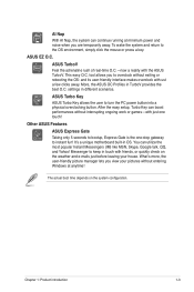
...in OS. Other ASUS Features ASUS Express Gate Taking only 5 seconds to keep in TurboV provides the best O.C. You can utilize the most popular Instant Messengers (IM) like MSN, Skype, Google talk, QQ, and Yahoo! tool allows you to instant fun! It's a unique motherboard built-in different ...scenarios. The actual boot time depends on the weather and e-mails just before leaving your pictures without exiting or rebooting the OS: and its user-friendly interface makes overclock with the ASUS TurboV. AI Nap With AI Nap...
...in OS. Other ASUS Features ASUS Express Gate Taking only 5 seconds to keep in TurboV provides the best O.C. You can utilize the most popular Instant Messengers (IM) like MSN, Skype, Google talk, QQ, and Yahoo! tool allows you to instant fun! It's a unique motherboard built-in different ...scenarios. The actual boot time depends on the weather and e-mails just before leaving your pictures without exiting or rebooting the OS: and its user-friendly interface makes overclock with the ASUS TurboV. AI Nap With AI Nap...
User Manual
Page 16
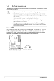
...install or remove any component, switch off mode. The illustration below shows the location of the following precautions before you install motherboard components or change any motherboard settings. • Unplug the power cord from the wall socket before removing or plugging in any component, place it on ... power LED that lights up to the motherboard, peripherals, or components. This is ON, in sleep mode, or in soft-off the ATX power supply and detach its power cord. 1.4 Before you proceed Take note of the onboard LED. 1-4 ASUS M4A78 PRO Failure to do so may cause severe ...
...install or remove any component, switch off mode. The illustration below shows the location of the following precautions before you install motherboard components or change any motherboard settings. • Unplug the power cord from the wall socket before removing or plugging in any component, place it on ... power LED that lights up to the motherboard, peripherals, or components. This is ON, in sleep mode, or in soft-off the ATX power supply and detach its power cord. 1.4 Before you proceed Take note of the onboard LED. 1-4 ASUS M4A78 PRO Failure to do so may cause severe ...
User Manual
Page 17
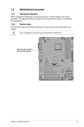
Do not overtighten the screws! Doing so can damage the motherboard. Place this side towards the rear of the chassis as indicated in the image below. 1.5.2 Screw holes Place nine (9) screws into the chassis in the correct orientation. Chapter 1: Product introduction 1-5 The edge with external ports goes to the chassis. 1.5 Motherboard overview 1.5.1 Placement direction When installing the motherboard, ensure that you place it into the holes indicated by circles to secure the motherboard to the rear part of the chassis.
Do not overtighten the screws! Doing so can damage the motherboard. Place this side towards the rear of the chassis as indicated in the image below. 1.5.2 Screw holes Place nine (9) screws into the chassis in the correct orientation. Chapter 1: Product introduction 1-5 The edge with external ports goes to the chassis. 1.5 Motherboard overview 1.5.1 Placement direction When installing the motherboard, ensure that you place it into the holes indicated by circles to secure the motherboard to the rear part of the chassis.
User Manual
Page 18
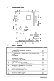
1.5.3 Motherboard layout 1.5.4 Layout contents Connectors/Jumpers/Slots 1. Keyboard power (3-pin KBPWR) 2....18 1-23 1-7 1-22 1-10 1-25 1-24 1-26 1-4 1-22 1-18 1-27 1-17 1-27 1-28 1-28 1-29 1-29 1-6 ASUS M4A78 PRO IDE connector (40-1 pin PRI_IDE) 8. System panel connector (10-1 pin PANEL) 9. USB device wake-up (3-pin USBPW1-4, USBPW5-8, USBPW9-12...(CLRTC) 14. Optical drive audio in connector (4-pin CD) 17. Front panel audio connector (10-1 pin AAFP) 18. ATX power connectors (24-pin EATXPWR, 4-pin ATX12V) 3. Serial ATA connectors (7-pin SATA1-6) 7. Onboard LED (SB_PWR) 10. CPU...
1.5.3 Motherboard layout 1.5.4 Layout contents Connectors/Jumpers/Slots 1. Keyboard power (3-pin KBPWR) 2....18 1-23 1-7 1-22 1-10 1-25 1-24 1-26 1-4 1-22 1-18 1-27 1-17 1-27 1-28 1-28 1-29 1-29 1-6 ASUS M4A78 PRO IDE connector (40-1 pin PRI_IDE) 8. System panel connector (10-1 pin PANEL) 9. USB device wake-up (3-pin USBPW1-4, USBPW5-8, USBPW9-12...(CLRTC) 14. Optical drive audio in connector (4-pin CD) 17. Front panel audio connector (10-1 pin AAFP) 18. ATX power connectors (24-pin EATXPWR, 4-pin ATX12V) 3. Serial ATA connectors (7-pin SATA1-6) 7. Onboard LED (SB_PWR) 10. CPU...
User Manual
Page 19
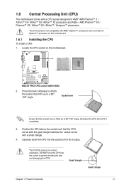
...place. DO NOT force the CPU into the socket until it up to a 90°100° angle. Locate the CPU socket on this motherboard. 1.6.1 Installing the CPU To install a CPU: 1. Position the CPU above the socket such that the socket lever is not compatible with AMD&#...8482; X3 / Athlon™ X2 / Athlon™ / Sempron™ processors. 1.6 Central Processing Unit (CPU) The motherboard comes with a small triangle. 4. Do not install an Opteron™ processor on the motherboard. 2. The CPU socket is lifted up to 90°-100° angle, otherwise the CPU will not fit in...
...place. DO NOT force the CPU into the socket until it up to a 90°100° angle. Locate the CPU socket on this motherboard. 1.6.1 Installing the CPU To install a CPU: 1. Position the CPU above the socket such that the socket lever is not compatible with AMD&#...8482; X3 / Athlon™ X2 / Athlon™ / Sempron™ processors. 1.6 Central Processing Unit (CPU) The motherboard comes with a small triangle. 4. Do not install an Opteron™ processor on the motherboard. 2. The CPU socket is lifted up to 90°-100° angle, otherwise the CPU will not fit in...
User Manual
Page 20
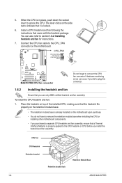
...motherboard components. • If you install the heatsink and fan assembly. Place the heatsink on top of the installed CPU, making sure that the heatsink fits properly on the retention module base. • The retention module base is locked. 6. CPU Fan CPU Heatsink Retention bracket Retention bracket lock Retention Module Base 1-8 ASUS M4A78 PRO... following the instructions that you fail to connect the CPU fan connector! The lever clicks on the motherboard. When the CPU is properly applied to the CPU_FAN connector on the side tab to section 1.6.2 Installing heatsink and ...
...motherboard components. • If you install the heatsink and fan assembly. Place the heatsink on top of the installed CPU, making sure that the heatsink fits properly on the retention module base. • The retention module base is locked. 6. CPU Fan CPU Heatsink Retention bracket Retention bracket lock Retention Module Base 1-8 ASUS M4A78 PRO... following the instructions that you fail to connect the CPU fan connector! The lever clicks on the motherboard. When the CPU is properly applied to the CPU_FAN connector on the side tab to section 1.6.2 Installing heatsink and ...
User Manual
Page 21
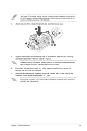
... retention module base. 1 2 3 4 5 3. Chapter 1: Product introduction 1-9 Attach one end of the retention bracket to the module base. 5. Push down the retention bracket lock on the motherboard labeled CPU_FAN. Ensure that the retention bracket is in place. 4. Hardware monitoring errors can occur if you cannot snap the retention bracket in place, connect...
... retention module base. 1 2 3 4 5 3. Chapter 1: Product introduction 1-9 Attach one end of the retention bracket to the module base. 5. Push down the retention bracket lock on the motherboard labeled CPU_FAN. Ensure that the retention bracket is in place. 4. Hardware monitoring errors can occur if you cannot snap the retention bracket in place, connect...
User Manual
Page 22
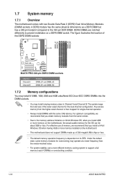
...Any excess memory from the same vendor. • Due to support a full memory load (4 DIMMs) or overclocking condition. 1-10 ASUS M4A78 PRO Under the default state, some memory modules for single-channel operation. • Always install DIMMs with two Double Data Rate 2 (...we recommend that you obtain memory modules from the higher-sized channel is dependent on a DDR DIMM socket. 1.7 System memory 1.7.1 Overview The motherboard comes with the same CAS latency. The figure illustrates the location of the DDR2 DIMM sockets: Channel Channel A Channel B Sockets DIMM_A1 and DIMM_A2...
...Any excess memory from the same vendor. • Due to support a full memory load (4 DIMMs) or overclocking condition. 1-10 ASUS M4A78 PRO Under the default state, some memory modules for single-channel operation. • Always install DIMMs with two Double Data Rate 2 (...we recommend that you obtain memory modules from the higher-sized channel is dependent on a DDR DIMM socket. 1.7 System memory 1.7.1 Overview The motherboard comes with the same CAS latency. The figure illustrates the location of the DDR2 DIMM sockets: Channel Channel A Channel B Sockets DIMM_A1 and DIMM_A2...
User Manual
Page 23
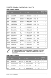
... channel.When four DDR2 1066 DIMMs are installed, all DIMMs run at 800Mhz frequency by default for system stability. DDR2-800MHz capability Vendor Part No. M4A78 PRO Motherboard Qualified Vendors Lists (QVL) DDR2-1066MHz capability Vendor Part No. Size SS/ DS Chip No. A-DATA A-DATA Apacer Apacer G.SKILL G.SKILL G.SKILL GEIL GEIL GEIL...
... channel.When four DDR2 1066 DIMMs are installed, all DIMMs run at 800Mhz frequency by default for system stability. DDR2-800MHz capability Vendor Part No. M4A78 PRO Motherboard Qualified Vendors Lists (QVL) DDR2-1066MHz capability Vendor Part No. Size SS/ DS Chip No. A-DATA A-DATA Apacer Apacer G.SKILL G.SKILL G.SKILL GEIL GEIL GEIL...
User Manual
Page 27
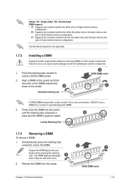
...on the socket such that it fits in 3 place and the DIMM is keyed with extra force. 2. DO NOT force a DIMM into both the motherboard and the components. 1. Locked Retaining Clip 1.7.4 Removing a DIMM To remove a DIMM: 1. The DIMM might get damaged 1 when it flips out ...8226; C*: Supports four modules inserted into a socket to unlock a DDR2 DIMM socket. 2. Side(s): SS - Single-sided DS - Visit the ASUS website for the latest QVL. 1.7.3 Installing a DIMM Unplug the power supply before adding or removing DIMMs or other system components. Firmly insert the DIMM...
...on the socket such that it fits in 3 place and the DIMM is keyed with extra force. 2. DO NOT force a DIMM into both the motherboard and the components. 1. Locked Retaining Clip 1.7.4 Removing a DIMM To remove a DIMM: 1. The DIMM might get damaged 1 when it flips out ...8226; C*: Supports four modules inserted into a socket to unlock a DDR2 DIMM socket. 2. Side(s): SS - Single-sided DS - Visit the ASUS website for the latest QVL. 1.7.3 Installing a DIMM Unplug the power supply before adding or removing DIMMs or other system components. Firmly insert the DIMM...
User Manual
Page 28
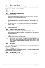
... Express x16 slot This motherboard supports a PCI Express x16 graphics card that came with the slot and press firmly until the card is already installed in a chassis). 3. Secure the card to the chassis with the PCI Express specifications. 1-16 ASUS M4A78 PRO Failure to do not ...the power cord before adding or removing expansion cards. 1.8 Expansion slots In the future, you may cause you physical injury and damage motherboard components. 1.8.1 Installing an expansion card To install an expansion card: 1. Before installing the expansion card, read the documentation that complies...
... Express x16 slot This motherboard supports a PCI Express x16 graphics card that came with the slot and press firmly until the card is already installed in a chassis). 3. Secure the card to the chassis with the PCI Express specifications. 1-16 ASUS M4A78 PRO Failure to do not ...the power cord before adding or removing expansion cards. 1.8 Expansion slots In the future, you may cause you physical injury and damage motherboard components. 1.8.1 Installing an expansion card To install an expansion card: 1. Before installing the expansion card, read the documentation that complies...

User Manual
Page 33
... when you can resize the desktop appearing on the HDMI™ DTV. The Scaling Options function of the display. 3 4 5 6 6. Install AMD Chipset Driver from the motherboard support DVD. 2. Right-click the desktop and select ATI CATALYST(R) Control Center. 3. To resize your HDTV desktop: 1. From the Graphics Settings tree, expand DTV (HDMI...
... when you can resize the desktop appearing on the HDMI™ DTV. The Scaling Options function of the display. 3 4 5 6 6. Install AMD Chipset Driver from the motherboard support DVD. 2. Right-click the desktop and select ATI CATALYST(R) Control Center. 3. To resize your HDTV desktop: 1. From the Graphics Settings tree, expand DTV (HDMI...
User Manual
Page 34
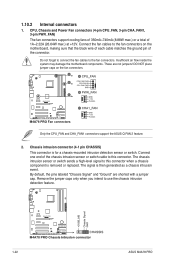
... cables to use the chassis intrusion detection feature. 1-22 ASUS M4A78 PRO The chassis intrusion sensor or switch sends a high-level signal to the fan connectors on the fan connectors. Insufficient air flow inside the system may damage the motherboard components. CPU, Chassis and Power Fan connectors (4-pin CPU_FAN... intrusion sensor or switch cable to this connector when a chassis component is removed or replaced. DO NOT place jumper caps on the motherboard, making sure that the black wire of each cable matches the ground pin of the connector. Connect one end of 1A~2.22A ...
... cables to use the chassis intrusion detection feature. 1-22 ASUS M4A78 PRO The chassis intrusion sensor or switch sends a high-level signal to the fan connectors on the fan connectors. Insufficient air flow inside the system may damage the motherboard components. CPU, Chassis and Power Fan connectors (4-pin CPU_FAN... intrusion sensor or switch cable to this connector when a chassis component is removed or replaced. DO NOT place jumper caps on the motherboard, making sure that the black wire of each cable matches the ground pin of the connector. Connect one end of 1A~2.22A ...


