User Manual
Page 16
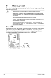
...to indicate that the system is a reminder that you install or remove any motherboard settings. • Unplug the power cord from the wall socket before removing or plugging in soft-off the ATX power supply and detach its power cord. The illustration below shows the location... any motherboard component. This is ON, in sleep mode, or in any component, place it on a grounded antistatic pad or in the bag that came with a standby power LED that lights up to the motherboard, peripherals, or components. 1.4 Before you proceed Take note of the onboard LED. 1-4 ASUS M4A78 PRO
...to indicate that the system is a reminder that you install or remove any motherboard settings. • Unplug the power cord from the wall socket before removing or plugging in soft-off the ATX power supply and detach its power cord. The illustration below shows the location... any motherboard component. This is ON, in sleep mode, or in any component, place it on a grounded antistatic pad or in the bag that came with a standby power LED that lights up to the motherboard, peripherals, or components. 1.4 Before you proceed Take note of the onboard LED. 1-4 ASUS M4A78 PRO
User Manual
Page 18
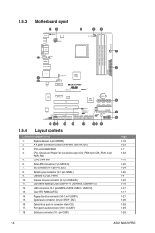
... 1-10 1-25 1-24 1-26 1-4 1-22 1-18 1-27 1-17 1-27 1-28 1-28 1-29 1-29 1-6 ASUS M4A78 PRO System panel connector (10-1 pin PANEL) 9. Onboard LED (SB_PWR) 10. Floppy disk drive connector (34-1 pin FLOPPY) 15. 1.5.3 Motherboard layout 1.5.4 Layout contents Connectors/Jumpers/Slots 1. ATX power connectors (24-pin EATXPWR, 4-pin ATX12V) 3. DDR2 DIMM slots 6. Serial ATA connectors...
... 1-10 1-25 1-24 1-26 1-4 1-22 1-18 1-27 1-17 1-27 1-28 1-28 1-29 1-29 1-6 ASUS M4A78 PRO System panel connector (10-1 pin PANEL) 9. Onboard LED (SB_PWR) 10. Floppy disk drive connector (34-1 pin FLOPPY) 15. 1.5.3 Motherboard layout 1.5.4 Layout contents Connectors/Jumpers/Slots 1. ATX power connectors (24-pin EATXPWR, 4-pin ATX12V) 3. DDR2 DIMM slots 6. Serial ATA connectors...


