User Manual
Page 3
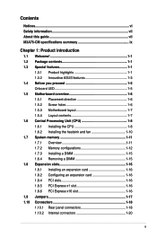
... information vii About this guide vii M3A76-CM specifications summary ix Chapter 1: Product introduction 1.1 Welcome 1-1 1.2 Package contents 1-1 1.3 Special features 1-1 1.3.1 Product highlights 1-1 1.3.2 Innovative ASUS features 1-3 1.4 Before you proceed 1-5 Onboard LED 1-5 1.5 Motherboard overview 1-6 1.5.1 Placement direction 1-6 1.5.2 Screw holes 1-6 1.5.3 Motherboard layout 1-7 1.5.4 Layout contents 1-7 ... Express x1 slot 1-16 1.8.6 PCI Express x16 slot 1-16 1.9 Jumpers 1-17 1.10 Connectors 1-18 1.10.1 Rear panel connectors 1-18 1.10.2 Internal connectors 1-20 iii
... information vii About this guide vii M3A76-CM specifications summary ix Chapter 1: Product introduction 1.1 Welcome 1-1 1.2 Package contents 1-1 1.3 Special features 1-1 1.3.1 Product highlights 1-1 1.3.2 Innovative ASUS features 1-3 1.4 Before you proceed 1-5 Onboard LED 1-5 1.5 Motherboard overview 1-6 1.5.1 Placement direction 1-6 1.5.2 Screw holes 1-6 1.5.3 Motherboard layout 1-7 1.5.4 Layout contents 1-7 ... Express x1 slot 1-16 1.8.6 PCI Express x16 slot 1-16 1.9 Jumpers 1-17 1.10 Connectors 1-18 1.10.1 Rear panel connectors 1-18 1.10.2 Internal connectors 1-20 iii
User Manual
Page 17
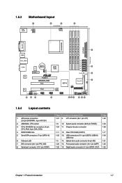
.... CPU, CHASSIS fan connectors (4-pin CPU_FAN, 3-pin CHA_FAN) 4. Clear RTC RAM (CLRTC) 1-17 1-22 13. 1.5.3 Motherboard layout 1.5.4 Layout contents Connectors/Jumpers/Slots 1. Chassis intrusion connector 1-26 1-11 12. System panel connector (20-8 pin PANEL) 1-23 1-24 11. ATX power connectors (24-pin EATXPWR, 4-pin ATX12V) 2. Serial ATA connectors (7-pin SATA1-6) 6. Front panel audio...
.... CPU, CHASSIS fan connectors (4-pin CPU_FAN, 3-pin CHA_FAN) 4. Clear RTC RAM (CLRTC) 1-17 1-22 13. 1.5.3 Motherboard layout 1.5.4 Layout contents Connectors/Jumpers/Slots 1. Chassis intrusion connector 1-26 1-11 12. System panel connector (20-8 pin PANEL) 1-23 1-24 11. ATX power connectors (24-pin EATXPWR, 4-pin ATX12V) 2. Serial ATA connectors (7-pin SATA1-6) 6. Front panel audio...

User Manual
Page 27
... from pins 1-2 (default) to default values. Keep the cap on CLRTC jumper default position. Shut down the key during the boot process and enter BIOS setup to overclocking, use the CPU Parameter Recall (C.P.R) feature. To erase the ... the computer and unplug the power cord. 2. The onboard button cell battery powers the RAM data in CMOS. For system failure due to reenter data. 1.9 Jumpers 1. Except when clearing the RTC RAM, never remove the cap on pins 2-3 for about 5~10 seconds, then move the...
... from pins 1-2 (default) to default values. Keep the cap on CLRTC jumper default position. Shut down the key during the boot process and enter BIOS setup to overclocking, use the CPU Parameter Recall (C.P.R) feature. To erase the ... the computer and unplug the power cord. 2. The onboard button cell battery powers the RAM data in CMOS. For system failure due to reenter data. 1.9 Jumpers 1. Except when clearing the RTC RAM, never remove the cap on pins 2-3 for about 5~10 seconds, then move the...

User Manual
Page 30
... connector is set as "Cable-Select," make sure all other device jumpers have the same setting. 1-20 ASUS M3A76-CM Connect the serial port module cable to the connector, then install the module to configure your device(s). Connect the blue connector to the motherboard's IDE connector, then select one of the following modes to a slot...
... connector is set as "Cable-Select," make sure all other device jumpers have the same setting. 1-20 ASUS M3A76-CM Connect the serial port module cable to the connector, then install the module to configure your device(s). Connect the blue connector to the motherboard's IDE connector, then select one of the following modes to a slot...

User Manual
Page 34
...cable to 480 Mbps connection speed. DO NOT place jumper caps on the motherboard, ensuring that supports up to the USB connectors. Doing so will damage the motherboard! Insufficient air flow inside the system may damage the motherboard components. These are for USB 2.0 ports. These... chassis. 8. USB connectors (10-1 pin USB78, USB910, USB1112) These connectors are not jumpers! The USB 2.0 module is purchased separately. 9. Only the CPU FAN supports ASUS Q-Fan. 1-24 ASUS M3A76-CM CPU and Chassis Fan connectors (4 pin CPU_FAN, 3-pin CHA_FAN) The fan connectors support cooling...
...cable to 480 Mbps connection speed. DO NOT place jumper caps on the motherboard, ensuring that supports up to the USB connectors. Doing so will damage the motherboard! Insufficient air flow inside the system may damage the motherboard components. These are for USB 2.0 ports. These... chassis. 8. USB connectors (10-1 pin USB78, USB910, USB1112) These connectors are not jumpers! The USB 2.0 module is purchased separately. 9. Only the CPU FAN supports ASUS Q-Fan. 1-24 ASUS M3A76-CM CPU and Chassis Fan connectors (4 pin CPU_FAN, 3-pin CHA_FAN) The fan connectors support cooling...
User Manual
Page 36
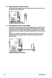
... chassis intrusion sensor or switch cable to receive stereo audio input from sound sources such as a chassis intrusion event. Remove the jumper caps only when you to this connector when a chassis component is removed or replaced. Optical drive audio in connector (4-pin CD)...chassis intrusion sensor or switch sends a high-level signal to use the chassis intrusion detection feature. 1-26 ASUS M3A76-CM By default, the pin labeled "Chassis Signal" and "Ground" are shorted with a jumper cap. Chassis intrusion connector (4-1 pin CHASSIS) This connector is then generated as a CD-ROM, TV ...
... chassis intrusion sensor or switch cable to receive stereo audio input from sound sources such as a chassis intrusion event. Remove the jumper caps only when you to this connector when a chassis component is removed or replaced. Optical drive audio in connector (4-pin CD)...chassis intrusion sensor or switch sends a high-level signal to use the chassis intrusion detection feature. 1-26 ASUS M3A76-CM By default, the pin labeled "Chassis Signal" and "Ground" are shorted with a jumper cap. Chassis intrusion connector (4-1 pin CHASSIS) This connector is then generated as a CD-ROM, TV ...
User Manual
Page 56
..., the system displays the message Press DEL to the Setup utility. Select the Change Supervisor Password item and press . 2. See section "1.9 Jumpers" for the F1 key to be pressed when error occurs. User Access Level [Full Access] This item allows you forget your password. The... prevents user access to run Setup during POST. Limited allows changes only to selected fields, such as in the Setup utility. 2-18 ASUS M3A76-CM Change Supervisor Password Select this item shows Installed. To change the system security settings. From the password box, type a password composed of...
..., the system displays the message Press DEL to the Setup utility. Select the Change Supervisor Password item and press . 2. See section "1.9 Jumpers" for the F1 key to be pressed when error occurs. User Access Level [Full Access] This item allows you forget your password. The... prevents user access to run Setup during POST. Limited allows changes only to selected fields, such as in the Setup utility. 2-18 ASUS M3A76-CM Change Supervisor Password Select this item shows Installed. To change the system security settings. From the password box, type a password composed of...

