User Manual
Page 17
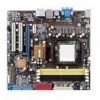
... USB connectors (10-1 pin USB78, USB910, 1-24 USB1112) 1-5 14. Optical drive audio connector (4-pin CD) 1-21 1-20 15. Onboard LED 7. Clear RTC RAM (CLRTC) 1-17 1-22 13. 1.5.3 Motherboard layout 1.5.4 Layout contents Connectors/Jumpers/Slots 1. Front panel audio connector (10-1 pin AAFP) 1-25 1-20 16 Digital audio connector (4-1 pin SPDIF_OUT) 1-25 Chapter...20-8 pin PANEL) 1-23 1-24 11. AM2/AM2+ CPU socket 3. CPU, CHASSIS fan connectors (4-pin CPU_FAN, 3-pin CHA_FAN) 4. Serial ATA connectors (7-pin SATA1-6) 6. ATX power connectors (24-pin EATXPWR, 4-pin ATX12V) 2.
... USB connectors (10-1 pin USB78, USB910, 1-24 USB1112) 1-5 14. Optical drive audio connector (4-pin CD) 1-21 1-20 15. Onboard LED 7. Clear RTC RAM (CLRTC) 1-17 1-22 13. 1.5.3 Motherboard layout 1.5.4 Layout contents Connectors/Jumpers/Slots 1. Front panel audio connector (10-1 pin AAFP) 1-25 1-20 16 Digital audio connector (4-1 pin SPDIF_OUT) 1-25 Chapter...20-8 pin PANEL) 1-23 1-24 11. AM2/AM2+ CPU socket 3. CPU, CHASSIS fan connectors (4-pin CPU_FAN, 3-pin CHA_FAN) 4. Serial ATA connectors (7-pin SATA1-6) 6. ATX power connectors (24-pin EATXPWR, 4-pin ATX12V) 2.

User Manual
Page 27
...! • If the steps above do not need to clear the RTC when the system hangs due to clear the Real Time Clock (RTC) RAM in CMOS, which include system setup information such as system passwords. For system failure due to pins 2-3. Chapter 1: Product introduction 1-17 Keep the ...cap on CLRTC jumper default position. The onboard button cell battery powers the RAM data in CMOS. Move the jumper cap from pins 1-2 (default) to overclocking, use the CPU Parameter Recall (C.P.R) feature. Clear RTC...
...! • If the steps above do not need to clear the RTC when the system hangs due to clear the Real Time Clock (RTC) RAM in CMOS, which include system setup information such as system passwords. For system failure due to pins 2-3. Chapter 1: Product introduction 1-17 Keep the ...cap on CLRTC jumper default position. The onboard button cell battery powers the RAM data in CMOS. Move the jumper cap from pins 1-2 (default) to overclocking, use the CPU Parameter Recall (C.P.R) feature. Clear RTC...

User Manual
Page 42
...8GB. • DO NOT shut down the system properly from the ASUS website at www.asus.com. 2.2 BIOS setup program This motherboard supports a programmable Serial Peripheral Interface (SPI) chip that the computer...data or system. This section explains how to your system using the navigation keys. 2-4 ASUS M3A76-CM This requires you are not prompted to use as easy to reconfigure your system using the... provided utility described in section "2.1 Managing and updating your computer in the CMOS RAM of your BIOS." Using the power button, reset button, or the ++ keys to "...
...8GB. • DO NOT shut down the system properly from the ASUS website at www.asus.com. 2.2 BIOS setup program This motherboard supports a programmable Serial Peripheral Interface (SPI) chip that the computer...data or system. This section explains how to your system using the navigation keys. 2-4 ASUS M3A76-CM This requires you are not prompted to use as easy to reconfigure your system using the... provided utility described in section "2.1 Managing and updating your computer in the CMOS RAM of your BIOS." Using the power button, reset button, or the ++ keys to "...

User Manual
Page 53
...] [Auto] USB 2.0 Controller Mode [HiSpeed] Allows you to add more tables for Advanced Configuration and Power Interface (ACPI) 2.0 specifications. Select an item then press to RAM) sleep state (default). The system can be used for System Suspend. 2.5.1 Suspend Mode [Auto] Allows you to enable or disable the Advanced Configuration and Power...
...] [Auto] USB 2.0 Controller Mode [HiSpeed] Allows you to add more tables for Advanced Configuration and Power Interface (ACPI) 2.0 specifications. Select an item then press to RAM) sleep state (default). The system can be used for System Suspend. 2.5.1 Suspend Mode [Auto] Allows you to enable or disable the Advanced Configuration and Power...
User Manual
Page 56
...] 2.6.3 Security The Security menu items allow you can clear it by erasing the CMOS Real Time Clock (RTC) RAM. The Supervisor Password item on how to erase the RTC RAM. From the password box, type a password composed of the screen shows the default Not Installed. If you forget ... least six letters and/or numbers, then press . 3. Limited allows changes only to selected fields, such as in the Setup utility. 2-18 ASUS M3A76-CM Full Access allows viewing and changing all the fields in setting a supervisor password. After you have set a supervisor password, the other items appear...
...] 2.6.3 Security The Security menu items allow you can clear it by erasing the CMOS Real Time Clock (RTC) RAM. The Supervisor Password item on how to erase the RTC RAM. From the password box, type a password composed of the screen shows the default Not Installed. If you forget ... least six letters and/or numbers, then press . 3. Limited allows changes only to selected fields, such as in the Setup utility. 2-18 ASUS M3A76-CM Full Access allows viewing and changing all the fields in setting a supervisor password. After you have set a supervisor password, the other items appear...

User Manual
Page 59
... if you do not want to save the changes that you made and restore the previously saved values. An onboard backup battery sustains the CMOS RAM so it stays on the Setup menus. When you select this option or if you select this option, a confirmation window appears. Pressing does not... discard the selections you made changes to fields other changes before saving the values to the non-volatile RAM. Chapter 2: BIOS setup 2-21 Exit & Save Changes Once you are saved to the CMOS RAM. Select OK to load default values. 2.8 Exit menu The Exit menu items allow you selected are finished...
... if you do not want to save the changes that you made and restore the previously saved values. An onboard backup battery sustains the CMOS RAM so it stays on the Setup menus. When you select this option or if you select this option, a confirmation window appears. Pressing does not... discard the selections you made changes to fields other changes before saving the values to the non-volatile RAM. Chapter 2: BIOS setup 2-21 Exit & Save Changes Once you are saved to the CMOS RAM. Select OK to load default values. 2.8 Exit menu The Exit menu items allow you selected are finished...


