
User Manual
Page 33
...程式(AWDFLASH.EXE BIOS AwardBIOS Flash BIOS 程式。 1 http://tw.asus.com BIOS M2N-VM HDMI.bin FAT 32/16 格式的 USB BIOS 2 CD/DVD AwardBIOS Flash BIOS 3 DOS 4. 當 A BIOS 檔案與 AwardBIOS Flash... 5 A awdflash 並按下 鍵。 AwardBIOS Flash Utility for ASUS V1.14 (C) Phoenix Technologies Ltd. PMC Pm49FL004T LPC...
...程式(AWDFLASH.EXE BIOS AwardBIOS Flash BIOS 程式。 1 http://tw.asus.com BIOS M2N-VM HDMI.bin FAT 32/16 格式的 USB BIOS 2 CD/DVD AwardBIOS Flash BIOS 3 DOS 4. 當 A BIOS 檔案與 AwardBIOS Flash... 5 A awdflash 並按下 鍵。 AwardBIOS Flash Utility for ASUS V1.14 (C) Phoenix Technologies Ltd. PMC Pm49FL004T LPC...
User Manual
Page 9
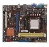
ASUS CrashFree BIOS3 - M2N68-AM SE2 specifications summary ASUS special features Back panel I/O ports Internal I /O ports 1 x COM port 3 x USB 2.0/1.1 connectors support additional 6 USB 2.0/1.1 ports 1 x IDE connector 2 x SATA connectors 1 x system panel connector 1 x CD audio-in connector 1 x Internal speaker connector 1 x Front panel audio connector 1 x CPU fan connector 1 x 24-pin EATX power connector 1 x 4-pin ATX 12V power connector 8Mb Flash...
ASUS CrashFree BIOS3 - M2N68-AM SE2 specifications summary ASUS special features Back panel I/O ports Internal I /O ports 1 x COM port 3 x USB 2.0/1.1 connectors support additional 6 USB 2.0/1.1 ports 1 x IDE connector 2 x SATA connectors 1 x system panel connector 1 x CD audio-in connector 1 x Internal speaker connector 1 x Front panel audio connector 1 x CPU fan connector 1 x 24-pin EATX power connector 1 x 4-pin ATX 12V power connector 8Mb Flash...
User Manual
Page 11
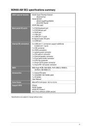
...PCIe x1/PCI slots Page 1-12 1-7 1-13 1-1 1-14 1-11 1-14 1-7 ASUS M2N68-AM SE2 1-2 Place this side towards the rear of the chassis. Clear RTC RAM (3-pin CLRTC) 11. Optical drive audio connector (4-pin CD) 15. CPU fan connector (4-pin CPU_FAN) 7. Serial ATA connectors (7-pin SATA1, SATA2... connector (4-pin SPEAKER) 12. ATX power connectors (24-pin EATXPWR, 4-pin ATX12V) 2. Place six screws into the chassis in the correct orientation. AM2 CPU Socket 3. Front panel audio connector (10-1 pin AAFP) 16. Doing so can damage the motherboard. 1.2.2 Layout contents Connectors/Jumpers/...
...PCIe x1/PCI slots Page 1-12 1-7 1-13 1-1 1-14 1-11 1-14 1-7 ASUS M2N68-AM SE2 1-2 Place this side towards the rear of the chassis. Clear RTC RAM (3-pin CLRTC) 11. Optical drive audio connector (4-pin CD) 15. CPU fan connector (4-pin CPU_FAN) 7. Serial ATA connectors (7-pin SATA1, SATA2... connector (4-pin SPEAKER) 12. ATX power connectors (24-pin EATXPWR, 4-pin ATX12V) 2. Place six screws into the chassis in the correct orientation. AM2 CPU Socket 3. Front panel audio connector (10-1 pin AAFP) 16. Doing so can damage the motherboard. 1.2.2 Layout contents Connectors/Jumpers/...
User Manual
Page 19
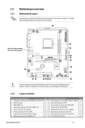
...(7-pin SATA1, SATA2) These connectors are for the Serial ATA signal cables for the function of this port becomes Front Speaker Out. 5. ASUS M2N68-AM SE2 1-10 Line In port (light blue). Audio 2, 4, 6-channel configuration Port Light Blue Lime Pink Headset 2-channel Line In Line Out Mic...compatible devices. 9. This port is for a PS/2 keyboard. 1.7.2 Internal connectors 1. This port connects to a microphone. This port connects to the tape, CD, DVD player, or other serial devices. 10. USB 2.0 ports 3 and 4. This 9-pin COM1 port is for pointing devices or other audio sources. ...
...(7-pin SATA1, SATA2) These connectors are for the Serial ATA signal cables for the function of this port becomes Front Speaker Out. 5. ASUS M2N68-AM SE2 1-10 Line In port (light blue). Audio 2, 4, 6-channel configuration Port Light Blue Lime Pink Headset 2-channel Line In Line Out Mic...compatible devices. 9. This port is for a PS/2 keyboard. 1.7.2 Internal connectors 1. This port connects to a microphone. This port connects to the tape, CD, DVD player, or other serial devices. 10. USB 2.0 ports 3 and 4. This 9-pin COM1 port is for pointing devices or other audio sources. ...
User Manual
Page 20
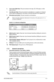
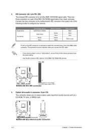
... DMA 133/100/66 IDE devices. 3. There are three connectors on the IDE connector is set as a CD-ROM, TV tuner, or MPEG card. 1-11 Chapter 1: Product introduction Connect the blue connector to the motherboard's IDE connector, then select one of device(s) - Master Slave Master Slave Cable connector Black Black Gray Black... the same setting. • Use the 80-conductor IDE cable for an Ultra DMA 133/100/66 signal cable. Optical drive audio in connector (4-pin CD) This connector allows you connect the IDE cable. • If any device jumper is removed to configure your devices.
... DMA 133/100/66 IDE devices. 3. There are three connectors on the IDE connector is set as a CD-ROM, TV tuner, or MPEG card. 1-11 Chapter 1: Product introduction Connect the blue connector to the motherboard's IDE connector, then select one of device(s) - Master Slave Master Slave Cable connector Black Black Gray Black... the same setting. • Use the 80-conductor IDE cable for an Ultra DMA 133/100/66 signal cable. Optical drive audio in connector (4-pin CD) This connector allows you connect the IDE cable. • If any device jumper is removed to configure your devices.
User Manual
Page 27
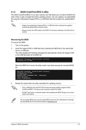
... on the system. 2. Bad BIOS checksum. Start Erasing... Doing so can update a corrupted BIOS file using this motherboard. Download the latest BIOS file from the ASUS website at www.asus.com. Starting BIOS recovery... Restart the system after the utility completes the updating process. • Only a USB ...while updating the BIOS! The utility displays the following message and automatically checks the Support DVD or the USB flash disk for CD-ROM... CD-ROM found , the utility reads it fails or gets corrupted during the updating process. Checking for the BIOS file. Starting BIOS...
... on the system. 2. Bad BIOS checksum. Start Erasing... Doing so can update a corrupted BIOS file using this motherboard. Download the latest BIOS file from the ASUS website at www.asus.com. Starting BIOS recovery... Restart the system after the utility completes the updating process. • Only a USB ...while updating the BIOS! The utility displays the following message and automatically checks the Support DVD or the USB flash disk for CD-ROM... CD-ROM found , the utility reads it fails or gets corrupted during the updating process. Checking for the BIOS file. Starting BIOS...
User Manual
Page 29
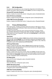
.... Configuration options: [Disabled] [Enabled] 2.3.4 Primary IDE Master/Slave While entering Setup, the BIOS automatically detects the presence of IDE drive. These values are specifically configuring a CD-ROM drive. Type [Auto] Selects the type of IDE devices. Configuration options: [Disabled] [Auto] Block (Multi-Sector Transfer) M [Auto] Enables or disables data multi-sectors...
.... Configuration options: [Disabled] [Enabled] 2.3.4 Primary IDE Master/Slave While entering Setup, the BIOS automatically detects the presence of IDE drive. These values are specifically configuring a CD-ROM drive. Type [Auto] Selects the type of IDE devices. Configuration options: [Disabled] [Auto] Block (Multi-Sector Transfer) M [Auto] Enables or disables data multi-sectors...
User Manual
Page 38
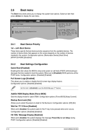
Configuration options: [Removable Device] [Hard Drive] [ATAPI CD-ROM ] [Disabled] 2.6.2 Boot Settings Configuration Quick Boot [Enabled] Enabling this item to [Enabled] to use the ASUS MyLogo 2™ feature. Configuration options: [Disabled] [Enabled] 2-14 ASUS M2N68-AM SE2 Select an item then press to change the system boot options...Error [Enabled] When set to Enabled, the system displays the message Press DEL to run Setup during POST. When set the CD-ROM drive as the first boot device. 2.6.1 Boot Device Priority 1st ~ xxth Boot Device These items specify the boot device ...
Configuration options: [Removable Device] [Hard Drive] [ATAPI CD-ROM ] [Disabled] 2.6.2 Boot Settings Configuration Quick Boot [Enabled] Enabling this item to [Enabled] to use the ASUS MyLogo 2™ feature. Configuration options: [Disabled] [Enabled] 2-14 ASUS M2N68-AM SE2 Select an item then press to change the system boot options...Error [Enabled] When set to Enabled, the system displays the message Press DEL to run Setup during POST. When set the CD-ROM drive as the first boot device. 2.6.1 Boot Device Priority 1st ~ xxth Boot Device These items specify the boot device ...


