M2N32 WS Professional English Edition User's Manual
Page 47
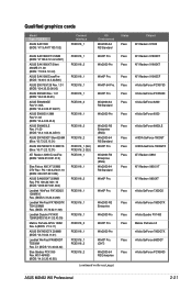
... GeForce 7800GTX nVidia GeForce 6800GT nVidia GeForce PCX5900 ASUS M2N32 WS Professional 2-21 Win2000 Pro PCIEX16_1 PCIEX16_1 PCIEX16_1 PCIEX16_2 PCIEX16_1 WinXP Pro. Win2003-64 R2 Standard Win2000 Pro PCIEX16_2 PCIEX16_2 PCIEX16_1 (SLI) PCIEX16_2 (SLI) PCIEX16_1 PCIEX16_1 PCIEX16_2 Win2003 R2 Enterprise (ENG) Win2003-64 R2 Standard WinXP Pro. PN: 109-A47401-10 (BIOS: V009.007.001.004) Leadtek WinFast PX7300GS...
... GeForce 7800GTX nVidia GeForce 6800GT nVidia GeForce PCX5900 ASUS M2N32 WS Professional 2-21 Win2000 Pro PCIEX16_1 PCIEX16_1 PCIEX16_1 PCIEX16_2 PCIEX16_1 WinXP Pro. Win2003-64 R2 Standard Win2000 Pro PCIEX16_2 PCIEX16_2 PCIEX16_1 (SLI) PCIEX16_2 (SLI) PCIEX16_1 PCIEX16_1 PCIEX16_2 Win2003 R2 Enterprise (ENG) Win2003-64 R2 Standard WinXP Pro. PN: 109-A47401-10 (BIOS: V009.007.001.004) Leadtek WinFast PX7300GS...
M2N32 WS Professional English Edition User's Manual
Page 49
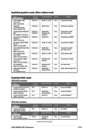
... the next page) Chipset LSI LS153C1030 ASUS M2N32 WS Professional 2-23 Win2003 R2 Standard (CHS) WinXP Pro. A (BIOS: V5.44.02.18) Leadtek WinFast PX6600GT TDH Rev. A (BIOS: V5.43.02.16) Elsa Gladiac 660LE 256MB Rev: 3C (BIOS: V5.43.02.69.E2) ASUS EN6200TC128/T/16M Rev V1.01 (BIOS: V5.44.02.11) ASUS EN6600 256M Rev. Qualified graphics...
... the next page) Chipset LSI LS153C1030 ASUS M2N32 WS Professional 2-23 Win2003 R2 Standard (CHS) WinXP Pro. A (BIOS: V5.44.02.18) Leadtek WinFast PX6600GT TDH Rev. A (BIOS: V5.43.02.16) Elsa Gladiac 660LE 256MB Rev: 3C (BIOS: V5.43.02.69.E2) ASUS EN6200TC128/T/16M Rev V1.01 (BIOS: V5.44.02.11) ASUS EN6600 256M Rev. Qualified graphics...
M2N32 WS Professional English Edition User's Manual
Page 51
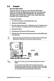
... and system setup parameters by erasing the CMOS RTC RAM data. For system failure due to default values. ASUS M2N32 WS Professional 2-25 Shut down the key during the boot process and enter BIOS setup to pins 2-3. Keep the cap on CLRTC jumper default position. 2.6 Jumper Clear RTC RAM (CLRTC) ...RTC when the system hangs due to overclocking. To erase the RTC RAM: 1. CLRTC M2N32 WS PRO ® 12 Normal (Default) M2N32 WS PRO Clear RTC RAM 23 Clear RTC • Make sure to re-enter your previous BIOS settings after you to pins 1-2. 4. Plug the power cord and turn ON the computer...
... and system setup parameters by erasing the CMOS RTC RAM data. For system failure due to default values. ASUS M2N32 WS Professional 2-25 Shut down the key during the boot process and enter BIOS setup to pins 2-3. Keep the cap on CLRTC jumper default position. 2.6 Jumper Clear RTC RAM (CLRTC) ...RTC when the system hangs due to overclocking. To erase the RTC RAM: 1. CLRTC M2N32 WS PRO ® 12 Normal (Default) M2N32 WS PRO Clear RTC RAM 23 Clear RTC • Make sure to re-enter your previous BIOS settings after you to pins 1-2. 4. Plug the power cord and turn ON the computer...
M2N32 WS Professional English Edition User's Manual
Page 57
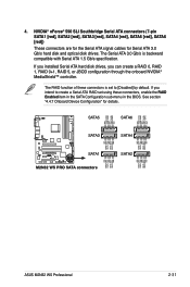
... RSATA_TXN4 GND RSATA_RXP4 RSATA_RXN4 GND GND RSATA_TXP3 RSATA_TXN3 GND RSATA_RXP3 RSATA_RXN3 GND GND RSATA_TXP2 RSATA_TXN2 GND RSATA_RXP2 RSATA_RXN2 GND M2N32 WS PRO ® SATA1 M2N32 WS PRO SATA connectors GND RSATA_TXP1 RSATA_TXN1 GND RSATA_RXP1 RSATA_RXN1 GND SATA2 ASUS M2N32 WS Professional 2-31 The RAID function of these connectors is backward compatible with Serial ATA 1.5 Gb/s specification. If you installed Serial... [Disabled] by default. The Serial ATA 3.0 Gb/s is set using these connectors, enable the RAID Enabled item in the SATA Configuration sub-menu in the BIOS.
... RSATA_TXN4 GND RSATA_RXP4 RSATA_RXN4 GND GND RSATA_TXP3 RSATA_TXN3 GND RSATA_RXP3 RSATA_RXN3 GND GND RSATA_TXP2 RSATA_TXN2 GND RSATA_RXP2 RSATA_RXN2 GND M2N32 WS PRO ® SATA1 M2N32 WS PRO SATA connectors GND RSATA_TXP1 RSATA_TXN1 GND RSATA_RXP1 RSATA_RXN1 GND SATA2 ASUS M2N32 WS Professional 2-31 The RAID function of these connectors is backward compatible with Serial ATA 1.5 Gb/s specification. If you installed Serial... [Disabled] by default. The Serial ATA 3.0 Gb/s is set using these connectors, enable the RAID Enabled item in the SATA Configuration sub-menu in the BIOS.
M2N32 WS Professional English Edition User's Manual
Page 62
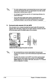
The system may become unstable or may not boot up if the power is set the Front Panel Support Type item in the BIOS to AC97. Front panel audio connector (10-1 pin AAFP) This connector is for details. 2-36 Chapter 2: Hardware information Connect one end of .... 11. GND PRESENCE# SENSE1_RETUR SENSE2_RETUR AGND NC NC NC PORT1 L PORT1 R PORT2 R SENSE_SEND PORT2 L MIC2 MICPWR Line out_R NC Line out_L M2N32 WS PRO ® AAFP M2N32 WS PRO Analog front panel connector • We recommend that you want to connect a legacy AC97 front panel audio module to connect the 4-pin ATX +12...
The system may become unstable or may not boot up if the power is set the Front Panel Support Type item in the BIOS to AC97. Front panel audio connector (10-1 pin AAFP) This connector is for details. 2-36 Chapter 2: Hardware information Connect one end of .... 11. GND PRESENCE# SENSE1_RETUR SENSE2_RETUR AGND NC NC NC PORT1 L PORT1 R PORT2 R SENSE_SEND PORT2 L MIC2 MICPWR Line out_R NC Line out_L M2N32 WS PRO ® AAFP M2N32 WS PRO Analog front panel connector • We recommend that you want to connect a legacy AC97 front panel audio module to connect the 4-pin ATX +12...
M2N32 WS Professional English Edition User's Manual
Page 65
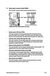
... beeps and warnings. • ATX power button/soft-off button (2-pin PWR) This connector is for the system power button. ASUS M2N32 WS Professional 2-39 PWR Ground Reset Ground M2N32 WS PRO ® IDE_LED RESET PWRSW * Requires an ATX power supply. The IDE LED lights up when you to the HDD. •.... 15. System panel connector (20-pin PANEL) This connector supports several chassis-mounted functions. The speaker allows you turn on the BIOS settings. Connect the chassis power LED cable to this connector. Pressing the power button turns the system on or puts the system in...
... beeps and warnings. • ATX power button/soft-off button (2-pin PWR) This connector is for the system power button. ASUS M2N32 WS Professional 2-39 PWR Ground Reset Ground M2N32 WS PRO ® IDE_LED RESET PWRSW * Requires an ATX power supply. The IDE LED lights up when you to the HDD. •.... 15. System panel connector (20-pin PANEL) This connector supports several chassis-mounted functions. The speaker allows you turn on the BIOS settings. Connect the chassis power LED cable to this connector. Pressing the power button turns the system on or puts the system in...


