
User Manual
Page 15
...solution provides KVM over IP solution. Discrete 8 channel audio card provides clearest high quality sounds ASUS KGPE-D16 1-3 Optional items PIKE 1064E PIKE 1068E PIKE 1078 PIKE 6480 PIKE 2008 ASMB4-iKVM ASUS MIO audio card Description LSI 4 port SAS RAID card LSI 8 port SAS RAID card ... Guide Packing Qty. Standard Gift Box Pack Standard Bulk Pack 6 -- 1 1 1 1 1 1 1pcs per carton 10pcs per carton If any of ASUS quality motherboards! 1.1 Welcome! The motherboard delivers a host of new features and latest technologies, making it , check the items in the long line of...
...solution provides KVM over IP solution. Discrete 8 channel audio card provides clearest high quality sounds ASUS KGPE-D16 1-3 Optional items PIKE 1064E PIKE 1068E PIKE 1078 PIKE 6480 PIKE 2008 ASMB4-iKVM ASUS MIO audio card Description LSI 4 port SAS RAID card LSI 8 port SAS RAID card ... Guide Packing Qty. Standard Gift Box Pack Standard Bulk Pack 6 -- 1 1 1 1 1 1 1pcs per carton 10pcs per carton If any of ASUS quality motherboards! 1.1 Welcome! The motherboard delivers a host of new features and latest technologies, making it , check the items in the long line of...
User Manual
Page 17
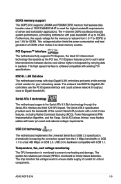
... Express™ interface The motherboard fully supports PCI Express, the latest I/O interconnect technology that features data transfer rates of 1333/1066/800 MHZ to 32GB/s. ASUS KGPE-D16 1-5 The 4-channel DDR3 architecture boosts system performance, eliminating bottlenecks with lower pin count and reduced voltage requirements. DDR3 memory support The...
... Express™ interface The motherboard fully supports PCI Express, the latest I/O interconnect technology that features data transfer rates of 1333/1066/800 MHZ to 32GB/s. ASUS KGPE-D16 1-5 The 4-channel DDR3 architecture boosts system performance, eliminating bottlenecks with lower pin count and reduced voltage requirements. DDR3 memory support The...
User Manual
Page 20
Chapter summary 2 2.1 Before you proceed 2-3 2.2 Motherboard overview 2-6 2.3 Central Processing Unit (CPU 2-10 2.4 System memory 2-16 2.5 Expansion slots 2-19 2.6 Jumpers 2-25 2.7 Connectors 2-30 ASUS KGPE-D16
Chapter summary 2 2.1 Before you proceed 2-3 2.2 Motherboard overview 2-6 2.3 Central Processing Unit (CPU 2-10 2.4 System memory 2-16 2.5 Expansion slots 2-19 2.6 Jumpers 2-25 2.7 Connectors 2-30 ASUS KGPE-D16

User Manual
Page 21
... motherboard components or change any motherboard settings. • Unplug the power cord from the power supply. 2.1 Before you proceed Take note of the onboard LED ASUS KGPE-D16 2-3 Standby Power LED The motherboard comes with the component. • Before you uninstall any component, place it on a grounded antistatic pad or in any component...
... motherboard components or change any motherboard settings. • Unplug the power cord from the power supply. 2.1 Before you proceed Take note of the onboard LED ASUS KGPE-D16 2-3 Standby Power LED The motherboard comes with the component. • Before you uninstall any component, place it on a grounded antistatic pad or in any component...

User Manual
Page 23
ASUS KGPE-D16 2-5 The heartbeat LED functions only when you install the ASUS ASMB4. BMC LED (BMC_LED1) The green heartbeat LED blinks per second to indicate that the ASMB4 is working normally. 4.
ASUS KGPE-D16 2-5 The heartbeat LED functions only when you install the ASUS ASMB4. BMC LED (BMC_LED1) The green heartbeat LED blinks per second to indicate that the ASMB4 is working normally. 4.
User Manual
Page 25
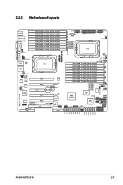
2.2.3 Motherboard layouts ASUS KGPE-D16 2-7
2.2.3 Motherboard layouts ASUS KGPE-D16 2-7

User Manual
Page 29
...;right corner of the arrow to the socket pins, do not remove the PnP cap unless you are installing a CPU. Gold triangle mark Alignment keys ASUS KGPE-D16 2-11 B Load lever 3. Load plate 4 5 PnP cap 3 6. Remove the PnP cap from the retention tab. DO NOT force the CPU into the CPU notch...
...;right corner of the arrow to the socket pins, do not remove the PnP cap unless you are installing a CPU. Gold triangle mark Alignment keys ASUS KGPE-D16 2-11 B Load lever 3. Load plate 4 5 PnP cap 3 6. Remove the PnP cap from the retention tab. DO NOT force the CPU into the CPU notch...
User Manual
Page 31
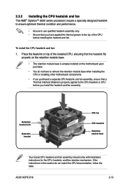
... CPU heatsink Retention module base Your boxed CPU heatsink and fan assembly should come with installation instructions for the CPU, heatsink, and the retention mechanism. ASUS KGPE-D16 2-13 If the instructions in this section do not have to remove the retention module base when installing the CPU or installing other motherboard components...
... CPU heatsink Retention module base Your boxed CPU heatsink and fan assembly should come with installation instructions for the CPU, heatsink, and the retention mechanism. ASUS KGPE-D16 2-13 If the instructions in this section do not have to remove the retention module base when installing the CPU or installing other motherboard components...
User Manual
Page 33
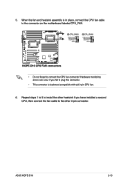
Hardware monitoring errors can occur if you have installed a second CPU, then connect the fan cable to connect the CPU fan connector! When the fan and heatsink assembly is backward compatible with old 3-pin CPU fan. 6. ASUS KGPE-D16 2-15 5. Repeat steps 1 to 5 to install the other heatsink if you fail to plug this connector. • This connector is in place, connect the CPU fan cable to the connector on the motherboard labeled CPU_FAN. • Do not forget to the other 4‑pin connector.
Hardware monitoring errors can occur if you have installed a second CPU, then connect the fan cable to connect the CPU fan connector! When the fan and heatsink assembly is backward compatible with old 3-pin CPU fan. 6. ASUS KGPE-D16 2-15 5. Repeat steps 1 to 5 to install the other heatsink if you fail to plug this connector. • This connector is in place, connect the CPU fan cable to the connector on the motherboard labeled CPU_FAN. • Do not forget to the other 4‑pin connector.

User Manual
Page 35
... CPU2 Single channel Dual channel Triple channel Qual channel A1 A2 B1 B2 C1 C2 D1 D2 V V V V V V V V V V V V V V V V V V E1 E2 F1 F2 G1 G2 H1 H2 V V V V V V V V V V V V V V V V V V ASUS KGPE-D16 2-17 For optimum compatibility, it is recommended that you obtain memory modules from the same vendor. • For CPU1 configuraton, when installing only one DIMM...
... CPU2 Single channel Dual channel Triple channel Qual channel A1 A2 B1 B2 C1 C2 D1 D2 V V V V V V V V V V V V V V V V V V E1 E2 F1 F2 G1 G2 H1 H2 V V V V V V V V V V V V V V V V V V ASUS KGPE-D16 2-17 For optimum compatibility, it is recommended that you obtain memory modules from the same vendor. • For CPU1 configuraton, when installing only one DIMM...

User Manual
Page 37
... intend to install expansion cards. Remove the system unit cover (if your motherboard is completely seated on the slot. 5. Keep the screw for the card. 2. ASUS KGPE-D16 2-19 Before installing the expansion card, read the documentation that the cards do so may need IRQ assignments. Turn on BIOS setup. 2. Assign an IRQ...
... intend to install expansion cards. Remove the system unit cover (if your motherboard is completely seated on the slot. 5. Keep the screw for the card. 2. ASUS KGPE-D16 2-19 Before installing the expansion card, read the documentation that the cards do so may need IRQ assignments. Turn on BIOS setup. 2. Assign an IRQ...

User Manual
Page 39
ASUS KGPE-D16 2-21 x8 link) The onboard PCI Express x16 slots provides two x16 link or one x16 link and... performance add-on your preferred SAS solution easily. PCI-E x16 slot (Gen2 x16 link) (Auto turn off if slot location 5 is for ASUS PIKE RAID card only. MIO supported) PCI-E x16 slot (Gen2 x16 link) PCI-E x8 slot (Gen2 x4 link) PCI-E x16 slot ...(Gen2 x16 link) (Auto switch to choose and change your needs. Install an optional ASUS PIKE RAID card based on cards. 2.5.6 PCI slot The PCI slot supports cards such as a LAN card, SCSI card, USB card, ...
ASUS KGPE-D16 2-21 x8 link) The onboard PCI Express x16 slots provides two x16 link or one x16 link and... performance add-on your preferred SAS solution easily. PCI-E x16 slot (Gen2 x16 link) (Auto turn off if slot location 5 is for ASUS PIKE RAID card only. MIO supported) PCI-E x16 slot (Gen2 x16 link) PCI-E x8 slot (Gen2 x4 link) PCI-E x16 slot ...(Gen2 x16 link) (Auto switch to choose and change your needs. Install an optional ASUS PIKE RAID card based on cards. 2.5.6 PCI slot The PCI slot supports cards such as a LAN card, SCSI card, USB card, ...

User Manual
Page 41
Snap the I Button in place. ASUS KGPE-D16 2-23 Orient and press the ASMB4 management card in place. Locate the I Button before using PIKE 1078 functions. 2.5.10 Installing ASMB4 management board Follow the steps below to install an optional ASMB4 management board on the motherboard. 2. You need to install I Button slot on your motherboard. 1. 2.5.9 Installing i Button Follow the steps below to install an optional i Button on the motherboard. 2. Locate the BMC_FW header on your motherboard. 1.
Snap the I Button in place. ASUS KGPE-D16 2-23 Orient and press the ASMB4 management card in place. Locate the I Button before using PIKE 1078 functions. 2.5.10 Installing ASMB4 management board Follow the steps below to install an optional ASMB4 management board on the motherboard. 2. You need to install I Button slot on your motherboard. 1. 2.5.9 Installing i Button Follow the steps below to install an optional i Button on the motherboard. 2. Locate the BMC_FW header on your motherboard. 1.

User Manual
Page 43
... Clock (RTC) RAM in CMOS, which include system setup information such as system passwords. The onboard button cell battery powers the RAM data in CMOS. ASUS KGPE-D16 2-25 2.6 Jumpers 1. Clear RTC RAM (CLRTC1) This jumper allows you to pins 1- 2. 3. Removing the cap will cause system boot failure!
... Clock (RTC) RAM in CMOS, which include system setup information such as system passwords. The onboard button cell battery powers the RAM data in CMOS. ASUS KGPE-D16 2-25 2.6 Jumpers 1. Clear RTC RAM (CLRTC1) This jumper allows you to pins 1- 2. 3. Removing the cap will cause system boot failure!

User Manual
Page 45
DDR3 voltage control setting (4-pin LVDDR3_SEL1; Set to pins 1-2 to select 1.5V BIOS control, pins 2-3 to select 1.2V Force or 3-4 to activate the Gigabit LAN feature. 5. ASUS KGPE-D16 2-27 LVDDR3_SEL2) These jumpers allow you to enable or disable the onboard Intel® 82574L Gigabit LAN controllers. 4. LAN controller setting (3-pin LAN_SW1, LAN_SW2) These jumpers allow you to adjust the DIMM voltage. Set to pins 1-2 to select 1.35V Force.
DDR3 voltage control setting (4-pin LVDDR3_SEL1; Set to pins 1-2 to select 1.5V BIOS control, pins 2-3 to select 1.2V Force or 3-4 to activate the Gigabit LAN feature. 5. ASUS KGPE-D16 2-27 LVDDR3_SEL2) These jumpers allow you to enable or disable the onboard Intel® 82574L Gigabit LAN controllers. 4. LAN controller setting (3-pin LAN_SW1, LAN_SW2) These jumpers allow you to adjust the DIMM voltage. Set to pins 1-2 to select 1.35V Force.

User Manual
Page 47
Shut down the system. 4. To update the BIOS: 1. Force BIOS recovery setting (3-pin RECOVERY1) This jumper allows you to pins 2-3. 2. Set the jumper to quickly update or recover the BIOS settings when it becomes corrupted. Set the jumper back to recover or update the BIOS. 3. Insert the USB flash that contains the original or latest BIOS and turn on the system. ASUS KGPE-D16 2-29 8. Turn on the system to pins 1-2. 5.
Shut down the system. 4. To update the BIOS: 1. Force BIOS recovery setting (3-pin RECOVERY1) This jumper allows you to pins 2-3. 2. Set the jumper to quickly update or recover the BIOS settings when it becomes corrupted. Set the jumper back to recover or update the BIOS. 3. Insert the USB flash that contains the original or latest BIOS and turn on the system. ASUS KGPE-D16 2-29 8. Turn on the system to pins 1-2. 5.

User Manual
Page 49
The actual data transfer rate depends on the speed of data transfer rate. Black) Supported by the AMD® SP5100 chipset, these connectors are for the Serial ATA signal cables for Serial ATA hard disk drives that allows up to 3Gb/s of Serial ATA hard disks installed. 2.7.2 Internal connectors 1. ASUS KGPE-D16 2-31 RED) (7-pin SATA5, SATA6; Serial ATA connectors (7-pin SATA1, SATA2, SATA3, SATA4;
The actual data transfer rate depends on the speed of data transfer rate. Black) Supported by the AMD® SP5100 chipset, these connectors are for the Serial ATA signal cables for Serial ATA hard disk drives that allows up to 3Gb/s of Serial ATA hard disks installed. 2.7.2 Internal connectors 1. ASUS KGPE-D16 2-31 RED) (7-pin SATA5, SATA6; Serial ATA connectors (7-pin SATA1, SATA2, SATA3, SATA4;

User Manual
Page 51
... to 480 Mbps connection speed. 5. These USB connectors comply with USB 2.0 specification that supports up to a slot opening at the back of the system chassis. ASUS KGPE-D16 2-33 A-Type USB9) These connectors are for USB 2.0 ports. Thermal sensor cable connectors (3-pin TR1, TR2) These connectors are for temperature monitoring. USB connector (10...
... to 480 Mbps connection speed. 5. These USB connectors comply with USB 2.0 specification that supports up to a slot opening at the back of the system chassis. ASUS KGPE-D16 2-33 A-Type USB9) These connectors are for USB 2.0 ports. Thermal sensor cable connectors (3-pin TR1, TR2) These connectors are for temperature monitoring. USB connector (10...

User Manual
Page 53
Connect the IEEE 1394a module cable to this connector, then install the module to a slot opening at the back of the system chassis. 7. These connectors functions only when you install an ASUS PIKE SAS RAID card. 8. ASUS KGPE-D16 2-35 IEEE 1394a port connector (10-1 pin IE1394_2) This connector is used for an IEEE 1394a port. Serial General Purpose Input/Output connectors (8-1 pin SGPIO1/2) These connector is for the SAS chip SGPIO interface that controls the LED pattern generation, device information and general purpose data.
Connect the IEEE 1394a module cable to this connector, then install the module to a slot opening at the back of the system chassis. 7. These connectors functions only when you install an ASUS PIKE SAS RAID card. 8. ASUS KGPE-D16 2-35 IEEE 1394a port connector (10-1 pin IE1394_2) This connector is used for an IEEE 1394a port. Serial General Purpose Input/Output connectors (8-1 pin SGPIO1/2) These connector is for the SAS chip SGPIO interface that controls the LED pattern generation, device information and general purpose data.

User Manual
Page 55
A TPM system also helps enhance network security, protects digital identities, and ensures platform integrity. 12. ASUS KGPE-D16 2-37 Power Supply SMBus connector (5-pin PSUSMB1) This connector allows you to connect SMBus (System Management Bus) to the power supply unit to read PSU information. Devices communicate with an SMBus host and/or other SMBus devices using the SMBus interface. 11. TPM connector (20-1 pin TPM) This connector supports a Trusted Platform Module (TPM) system, which can securely store keys, digital certificates, passwords, and data.
A TPM system also helps enhance network security, protects digital identities, and ensures platform integrity. 12. ASUS KGPE-D16 2-37 Power Supply SMBus connector (5-pin PSUSMB1) This connector allows you to connect SMBus (System Management Bus) to the power supply unit to read PSU information. Devices communicate with an SMBus host and/or other SMBus devices using the SMBus interface. 11. TPM connector (20-1 pin TPM) This connector supports a Trusted Platform Module (TPM) system, which can securely store keys, digital certificates, passwords, and data.


