
Motherboard DIY Troubleshooting Guide
Page 1
K8N-VM Motherboard
K8N-VM Motherboard

Motherboard DIY Troubleshooting Guide
Page 3
Contents Notices vi Safety information vii k8N-VM specifications summary viii Chapter 1: Product introduction 1.1 Welcome 1-2 1.2 Package contents 1-2 1.3 Special features 1-2 1.3.1 Product highlights 1-2 1.3.2 Innovative ASUS features 1-4 1.4 Before you proceed 1-5 1.5 Motherboard overview 1-6 1.5.1 Motherboard layout 1-6 1.5.2 Placement direction 1-7 1.5.3 Screw holes 1-7 1.5.4 Layout contents 1-8 1.6 Central Processing Unit (CPU 1-9 1.7 System memory 1-11 1.7.1 Overview 1-11 1.7.2 Memory configurations 1-11 1.7.3 Installing a DIMM 1-14...
Contents Notices vi Safety information vii k8N-VM specifications summary viii Chapter 1: Product introduction 1.1 Welcome 1-2 1.2 Package contents 1-2 1.3 Special features 1-2 1.3.1 Product highlights 1-2 1.3.2 Innovative ASUS features 1-4 1.4 Before you proceed 1-5 1.5 Motherboard overview 1-6 1.5.1 Motherboard layout 1-6 1.5.2 Placement direction 1-7 1.5.3 Screw holes 1-7 1.5.4 Layout contents 1-8 1.6 Central Processing Unit (CPU 1-9 1.7 System memory 1-11 1.7.1 Overview 1-11 1.7.2 Memory configurations 1-11 1.7.3 Installing a DIMM 1-14...

Motherboard DIY Troubleshooting Guide
Page 7
...you are not sure about the voltage of the electrical outlet you add a device. • Before connecting or removing signal cables from the motherboard, ensure that all power cables are not damaged. If possible, disconnect all power cables from the existing system before you are using the ... make sure all the manuals that came with the product, contact a qualified service technician or your retailer. Operation safety • Before installing the motherboard and adding devices on a stable surface. • If you detect any area where it may become wet. • Place the product on ...
...you are not sure about the voltage of the electrical outlet you add a device. • Before connecting or removing signal cables from the motherboard, ensure that all power cables are not damaged. If possible, disconnect all power cables from the existing system before you are using the ... make sure all the manuals that came with the product, contact a qualified service technician or your retailer. Operation safety • Before installing the motherboard and adding devices on a stable surface. • If you detect any area where it may become wet. • Place the product on ...

Motherboard DIY Troubleshooting Guide
Page 11
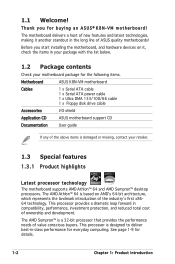
This chapter describes the motherboard features and the new technologies it supports. 1Product introduction
This chapter describes the motherboard features and the new technologies it supports. 1Product introduction
Motherboard DIY Troubleshooting Guide
Page 12
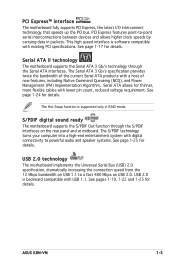
Before you for the following items. Motherboard ASUS K8N-VM motherboard Cables 1 x Serial ATA cable 1 x Serial ATA power cable 1 x Ultra DMA 133/100/66 cable 1 x Floppy disk drive cable Accessories I/O shield Application CD ASUS motherboard support CD Documentation User guide If any of the...industryʼs first x8664 technology. The AMD Sempron™ is damaged or missing, contact your motherboard package for buying an ASUS® K8N-VM motherboard! The motherboard delivers a host of new features and latest technologies, making it , check the items in -class ...
Before you for the following items. Motherboard ASUS K8N-VM motherboard Cables 1 x Serial ATA cable 1 x Serial ATA power cable 1 x Ultra DMA 133/100/66 cable 1 x Floppy disk drive cable Accessories I/O shield Application CD ASUS motherboard support CD Documentation User guide If any of the...industryʼs first x8664 technology. The AMD Sempron™ is damaged or missing, contact your motherboard package for buying an ASUS® K8N-VM motherboard! The motherboard delivers a host of new features and latest technologies, making it , check the items in -class ...
Motherboard DIY Troubleshooting Guide
Page 13
... through the S/PDIF interfaces on USB 2.0. USB 2.0 technology The motherboard implements the Universal Serial Bus (USB) 2.0 specification, dramatically increasing the connection speed from the 12 Mbps bandwidth on USB 1.1 to a fast 480 Mbps on the rear panel and at midboard. ASUS K8N-VM 1-3 This high speed interface is backward compatible with USB... by carrying data in RAID mode. See page 1-17 for details. The Hot Swap function is supported only in packets. S/PDIF digital sound ready The motherboard supports the S/PDIF Out function through the Serial ATA interfaces.
... through the S/PDIF interfaces on USB 2.0. USB 2.0 technology The motherboard implements the Universal Serial Bus (USB) 2.0 specification, dramatically increasing the connection speed from the 12 Mbps bandwidth on USB 1.1 to a fast 480 Mbps on the rear panel and at midboard. ASUS K8N-VM 1-3 This high speed interface is backward compatible with USB... by carrying data in RAID mode. See page 1-17 for details. The Hot Swap function is supported only in packets. S/PDIF digital sound ready The motherboard supports the S/PDIF Out function through the Serial ATA interfaces.
Motherboard DIY Troubleshooting Guide
Page 14
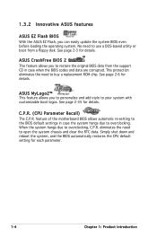
...eliminates the need to open the system chassis and clear the RTC data. See page 2-35 for each parameter. 1-4 Chapter 1: Product introduction ASUS CrashFree BIOS 2 This feature allows you to restore the original BIOS data from a floppy disk. Simply shut down and reboot the system..., and the BIOS automatically restores the CPU default setting for details. feature of the motherboard BIOS allows automatic re-setting to the BIOS default settings in case when the BIOS codes and data are corrupted. See page 2-6 for ...
...eliminates the need to open the system chassis and clear the RTC data. See page 2-35 for each parameter. 1-4 Chapter 1: Product introduction ASUS CrashFree BIOS 2 This feature allows you to restore the original BIOS data from a floppy disk. Simply shut down and reboot the system..., and the BIOS automatically restores the CPU default setting for details. feature of the motherboard BIOS allows automatic re-setting to the BIOS default settings in case when the BIOS codes and data are corrupted. See page 2-6 for ...
Motherboard DIY Troubleshooting Guide
Page 15
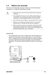
...Failure to do so may cause severe damage to indicate that the system is a reminder that you install or remove any motherboard component. Onboard LED The motherboard comes with the component. • Before you should shut down the system and unplug the power cable before handling components ... it on a grounded antistatic pad or in the bag that came with a standby power LED that lights up to the motherboard, peripherals, and/or components. R K8N-VM K8N-VM Onboard LED SB_PWR ON Standby Power OFF Powered Off ASUS K8N-VM 1-5 1.4 Before you proceed Take note of the onboard LED.
...Failure to do so may cause severe damage to indicate that the system is a reminder that you install or remove any motherboard component. Onboard LED The motherboard comes with the component. • Before you should shut down the system and unplug the power cable before handling components ... it on a grounded antistatic pad or in the bag that came with a standby power LED that lights up to the motherboard, peripherals, and/or components. R K8N-VM K8N-VM Onboard LED SB_PWR ON Standby Power OFF Powered Off ASUS K8N-VM 1-5 1.4 Before you proceed Take note of the onboard LED.

Motherboard DIY Troubleshooting Guide
Page 16
1.5 Motherboard overview 1.5.1 Motherboard layout 19.3cm (7.6in) PS/2 T: Mouse KBPWR B: Keyboard COM1 ATX12V CPU_FAN EATXPWR DDR DIMM1 (64 bit, 184-pin module) DDR DIMM2 (64 bit, 184-pin ... USBPW1234 Bottom: USB3 USB4 Top: RJ-45 Top:Line In Center:Line Out Below:Mic In Realtek 4Mb Flash ROM PCIEX1_1 Super I/O nVidia GeForce 6100 R K8N-VM PCIEX16 CD AAFP Audio SPDIF_OUT PCI1 SB_PWR PCI2 FLOPPY CR2032 3V Lithium Cell CMOS Powe nVidia nForce 410 SATA2 USBPW5678 USB56 USB78 SATA1 CLRTC PANEL...
1.5 Motherboard overview 1.5.1 Motherboard layout 19.3cm (7.6in) PS/2 T: Mouse KBPWR B: Keyboard COM1 ATX12V CPU_FAN EATXPWR DDR DIMM1 (64 bit, 184-pin module) DDR DIMM2 (64 bit, 184-pin ... USBPW1234 Bottom: USB3 USB4 Top: RJ-45 Top:Line In Center:Line Out Below:Mic In Realtek 4Mb Flash ROM PCIEX1_1 Super I/O nVidia GeForce 6100 R K8N-VM PCIEX16 CD AAFP Audio SPDIF_OUT PCI1 SB_PWR PCI2 FLOPPY CR2032 3V Lithium Cell CMOS Powe nVidia nForce 410 SATA2 USBPW5678 USB56 USB78 SATA1 CLRTC PANEL...

Motherboard DIY Troubleshooting Guide
Page 17
The edge with external ports goes to the chassis. Do not overtighten the screws! Doing so can damage the motherboard. Place this side towards the rear of the chassis as indicated in the correct orientation. 1.5.2 Placement direction When installing the motherboard, make sure that you place it into the chassis in the image below. 1.5.3 Screw holes Place six (6) screws into the holes indicated by circles to secure the motherboard to the rear part of the chassis R K8N-VM ASUS K8N-VM 1-7
The edge with external ports goes to the chassis. Do not overtighten the screws! Doing so can damage the motherboard. Place this side towards the rear of the chassis as indicated in the correct orientation. 1.5.2 Placement direction When installing the motherboard, make sure that you place it into the chassis in the image below. 1.5.3 Screw holes Place six (6) screws into the holes indicated by circles to secure the motherboard to the rear part of the chassis R K8N-VM ASUS K8N-VM 1-7
Motherboard DIY Troubleshooting Guide
Page 19
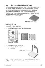
...the lever sideways, then lift it up to a 90°-100° angle. 1.6 Central Processing Unit (CPU) The motherboard comes with gold triangle) on the motherboard. Gold triangle Installing the CPU Follow these processors can run applications faster than processors with only 32-bit or 64-bit ...CPU does not fit in completely. Take note of these steps to ensure correct installation. Locate the 754-pin ZIF socket on the CPU. ASUS K8N-VM 1-9 R K8N-VM K8N-VM CPU Socket 754 2. This mark should match a specific corner on the socket to install a CPU. 1. The 128-bit-wide data...
...the lever sideways, then lift it up to a 90°-100° angle. 1.6 Central Processing Unit (CPU) The motherboard comes with gold triangle) on the motherboard. Gold triangle Installing the CPU Follow these processors can run applications faster than processors with only 32-bit or 64-bit ...CPU does not fit in completely. Take note of these steps to ensure correct installation. Locate the 754-pin ZIF socket on the CPU. ASUS K8N-VM 1-9 R K8N-VM K8N-VM CPU Socket 754 2. This mark should match a specific corner on the socket to install a CPU. 1. The 128-bit-wide data...

Motherboard DIY Troubleshooting Guide
Page 20
CPU_FAN R K8N-VM K8N-VM CPU Fan Connector Do not forget to plug this connector. Hardware monitoring errors can occur if you fail to connect the CPU fan connector! 3. The lever clicks on the motherboard. GND +12V Rotation 1-10 Chapter 1: Product introduction Position the CPU above the socket such that the CPU corner with the gold...
CPU_FAN R K8N-VM K8N-VM CPU Fan Connector Do not forget to plug this connector. Hardware monitoring errors can occur if you fail to connect the CPU fan connector! 3. The lever clicks on the motherboard. GND +12V Rotation 1-10 Chapter 1: Product introduction Position the CPU above the socket such that the CPU corner with the gold...
Motherboard DIY Troubleshooting Guide
Page 21
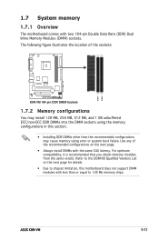
... DIMM sockets using the memory configurations in this section. • Installing DDR DIMMs other than or equal to chipset limitation, this motherboard does not support DIMM modules with two 184-pin Double Data Rate (DDR) Dual Inline Memory Modules (DIMM) sockets. Refer to the DDR400...memory chips. For optimum compatibility, it is recommended that you obtain memory modules from the same vendor. Use any of the sockets: R K8N-VM K8N-VM 184-pin DDR DIMM Sockets 1.7.2 Memory configurations You may cause memory sizing error or system boot failure. DIMM1 DIMM2 ASUS K8N-VM 1-11
... DIMM sockets using the memory configurations in this section. • Installing DDR DIMMs other than or equal to chipset limitation, this motherboard does not support DIMM modules with two 184-pin Double Data Rate (DDR) Dual Inline Memory Modules (DIMM) sockets. Refer to the DDR400...memory chips. For optimum compatibility, it is recommended that you obtain memory modules from the same vendor. Use any of the sockets: R K8N-VM K8N-VM 184-pin DDR DIMM Sockets 1.7.2 Memory configurations You may cause memory sizing error or system boot failure. DIMM1 DIMM2 ASUS K8N-VM 1-11

Motherboard DIY Troubleshooting Guide
Page 24
... the DIMM into a socket to unlock 1 the DIMM. 1 DDR DIMM notch Support the DIMM lightly with extra force. 2. 1.7.3 Installing a DIMM Make sure to both the motherboard and the components. 1.
... the DIMM into a socket to unlock 1 the DIMM. 1 DDR DIMM notch Support the DIMM lightly with extra force. 2. 1.7.3 Installing a DIMM Make sure to both the motherboard and the components. 1.

Motherboard DIY Troubleshooting Guide
Page 25
Make sure to the card. Remove the system unit cover (if your motherboard is completely seated on the system and change the necessary BIOS settings, if any. Keep the screw for the card. 2. Secure the card to the ... adjusting the software settings. 1. Remove the bracket opposite the slot that they support. See Chapter 2 for the expansion card. ASUS K8N-VM 1-15 1.8 Expansion slots In the future, you physical injury and damage motherboard components. 1.8.1 Installing an expansion card To install an expansion card: 1. Failure to do so may cause you may need to...
Make sure to the card. Remove the system unit cover (if your motherboard is completely seated on the system and change the necessary BIOS settings, if any. Keep the screw for the card. 2. Secure the card to the ... adjusting the software settings. 1. Remove the bracket opposite the slot that they support. See Chapter 2 for the expansion card. ASUS K8N-VM 1-15 1.8 Expansion slots In the future, you physical injury and damage motherboard components. 1.8.1 Installing an expansion card To install an expansion card: 1. Failure to do so may cause you may need to...

Motherboard DIY Troubleshooting Guide
Page 26
...* IRQ holder for PCI steering* PS/2 Compatible Mouse Port* Numeric Data Processor Primary IDE Channel Secondary IDE Channel * These IRQs are usually available for this motherboard PCI slot 1 PCI slot 2 A B C D - -
...* IRQ holder for PCI steering* PS/2 Compatible Mouse Port* Numeric Data Processor Primary IDE Channel Secondary IDE Channel * These IRQs are usually available for this motherboard PCI slot 1 PCI slot 2 A B C D - -
Motherboard DIY Troubleshooting Guide
Page 27
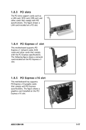
The following figure shows a network card installed on a PCI slot. 1.8.4 PCI Express x1 slot This motherboard supports PCI Express x1 network cards, SCSI cards and other cards that comply with PCI Express specifications. The figure shows a LAN ...card installed on the PCI Express x1 slot. 1.8.5 PCI Express x16 slot This motherboard has supports PCI Express x16 graphic cards that comply with PCI specifications. ASUS K8N-VM 1-17 The figure shows a graphics card installed on the PCI Express x16 slot. 1.8.3 PCI slots The PCI...
The following figure shows a network card installed on a PCI slot. 1.8.4 PCI Express x1 slot This motherboard supports PCI Express x1 network cards, SCSI cards and other cards that comply with PCI Express specifications. The figure shows a LAN ...card installed on the PCI Express x1 slot. 1.8.5 PCI Express x16 slot This motherboard has supports PCI Express x16 graphic cards that comply with PCI specifications. ASUS K8N-VM 1-17 The figure shows a graphics card installed on the PCI Express x16 slot. 1.8.3 PCI slots The PCI...
Motherboard DIY Troubleshooting Guide
Page 33
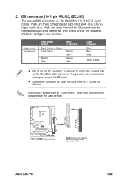
... SEC_IDE) The onboard IDE connectors are three connectors on the IDE ribbon cable to PIN 1. ASUS K8N-VM 1-23 There are for Ultra DMA 133/100/66 IDE devices. Connect the blue connector to the motherboardʼs IDE connector, then select one of device(s) Master Slave Master Slave Cable connector Black ... when you connect the IDE cable. • Use the 80-conductor IDE cable for Ultra DMA 133/100/66 signal cables. PIN1 SEC_IDE PRI_IDE R K8N-VM K8N-VM IDE Connectors PIN 1 NOTE: Orient the red markings (usually zigzag) on each Ultra DMA 133/100/66 signal cable: blue, black, and gray....
... SEC_IDE) The onboard IDE connectors are three connectors on the IDE ribbon cable to PIN 1. ASUS K8N-VM 1-23 There are for Ultra DMA 133/100/66 IDE devices. Connect the blue connector to the motherboardʼs IDE connector, then select one of device(s) Master Slave Master Slave Cable connector Black ... when you connect the IDE cable. • Use the 80-conductor IDE cable for Ultra DMA 133/100/66 signal cables. PIN1 SEC_IDE PRI_IDE R K8N-VM K8N-VM IDE Connectors PIN 1 NOTE: Orient the red markings (usually zigzag) on each Ultra DMA 133/100/66 signal cable: blue, black, and gray....
Motherboard DIY Troubleshooting Guide
Page 36
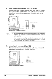
...-compliant pin definition AAFP AGND NC NC NC MIC2_L MIC2_R Line out_R NC Line out_L PORT1 L PORT1 R PORT2 R SENSE_SEND PORT2 L K8N-VM Analog Front Panel Connector • We recommend that you connect a high-definition front panel audio module to this connector to ...the Onboard AUDIO item in the BIOS is set to this connector. R K8N-VM K8N-VM Internal Audio Connector CD (black) Right Audio Channel Ground Ground Left Audio Channel 1-26 Chapter 1: Product introduction Connect one end of the motherboard high-definition audio capability. • If you to this connector...
...-compliant pin definition AAFP AGND NC NC NC MIC2_L MIC2_R Line out_R NC Line out_L PORT1 L PORT1 R PORT2 R SENSE_SEND PORT2 L K8N-VM Analog Front Panel Connector • We recommend that you connect a high-definition front panel audio module to this connector to ...the Onboard AUDIO item in the BIOS is set to this connector. R K8N-VM K8N-VM Internal Audio Connector CD (black) Right Audio Channel Ground Ground Left Audio Channel 1-26 Chapter 1: Product introduction Connect one end of the motherboard high-definition audio capability. • If you to this connector...
Motherboard DIY Troubleshooting Guide
Page 40
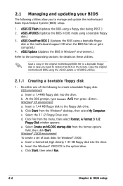
... disk in case you to manage and update the motherboard Basic Input/Output System (BIOS) setup. 1. c. d. Click File from the format options field, then click Start. e. Click Start, then select Run. 2-2 Chapter 2: BIOS setup ASUS AFUDOS (Updates the BIOS in the future. DOS environment... Click Start from the Windows® desktop, then select My Computer. b. ASUS Update (Updates the BIOS in Windows® environment.) Refer to the corresponding sections for Windows® 2000: a. Copy the original motherboard BIOS using a floppy disk during POST.) 2. Insert a 1.44 ...
... disk in case you to manage and update the motherboard Basic Input/Output System (BIOS) setup. 1. c. d. Click File from the format options field, then click Start. e. Click Start, then select Run. 2-2 Chapter 2: BIOS setup ASUS AFUDOS (Updates the BIOS in the future. DOS environment... Click Start from the Windows® desktop, then select My Computer. b. ASUS Update (Updates the BIOS in Windows® environment.) Refer to the corresponding sections for Windows® 2000: a. Copy the original motherboard BIOS using a floppy disk during POST.) 2. Insert a 1.44 ...


