User Manual
Page 1
R HX97 Pentium® Motherboard USER'S MANUAL
R HX97 Pentium® Motherboard USER'S MANUAL

User Manual
Page 2
... or may not be reproduced, transmitted, transcribed, stored in a retrieval system, or translated into any language in this manual are mentioned for a particular purpose. Product Name: ASUS HX97 Manual Revision: 1.01 Release Date: April 1997 2 ASUS HX97 User's Manual The product name and revision number are subject to change without the express written permission of ASUSTeK COMPUTER...
... or may not be reproduced, transmitted, transcribed, stored in a retrieval system, or translated into any language in this manual are mentioned for a particular purpose. Product Name: ASUS HX97 Manual Revision: 1.01 Release Date: April 1997 2 ASUS HX97 User's Manual The product name and revision number are subject to change without the express written permission of ASUSTeK COMPUTER...
User Manual
Page 3
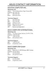
... Support: Fax: 886-2-895-9254 BBS: 886-2-896-4667 Email: tsd@asus.com.tw WWW: http://www.asus.com.tw/ Gopher: gopher.asus.com.tw FTP: ftp.asus.com.tw/pub/ASUS ASUS COMPUTER INTERNATIONAL Marketing Info: Address: 721 Charcot Avenue, San Jose, CA ...asus.com.tw Technical Support: BBS: 1-408-474-0555 Email: tsd-usa@asus.com.tw ASUS COMPUTER GmbH Marketing Info: Address: Harkort Str. 25, 40880 Ratingen, BRD, Germany Telephone: 49-2102-445011 Fax: 49-2102-442066 Email: info-ger@asus.com.tw Technical Support: BBS: 49-2102-448690 Email: tsd-ger@asus.com.tw ASUS HX97 User's Manual...
... Support: Fax: 886-2-895-9254 BBS: 886-2-896-4667 Email: tsd@asus.com.tw WWW: http://www.asus.com.tw/ Gopher: gopher.asus.com.tw FTP: ftp.asus.com.tw/pub/ASUS ASUS COMPUTER INTERNATIONAL Marketing Info: Address: 721 Charcot Avenue, San Jose, CA ...asus.com.tw Technical Support: BBS: 1-408-474-0555 Email: tsd-usa@asus.com.tw ASUS COMPUTER GmbH Marketing Info: Address: Harkort Str. 25, 40880 Ratingen, BRD, Germany Telephone: 49-2102-445011 Fax: 49-2102-442066 Email: info-ger@asus.com.tw Technical Support: BBS: 49-2102-448690 Email: tsd-ger@asus.com.tw ASUS HX97 User's Manual...

User Manual
Page 4
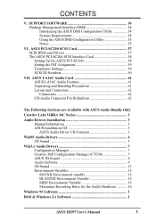
...Defaults 50 Supervisor Password and User Password 51 IDE HDD Auto Detection 52 Save and Exit Setup 53 Exit Without Saving 53 4 ASUS HX97 User's Manual System Memory (SIMM 17 SIMM Memory Installation 18 3. External Connectors 22 Power Connection Procedures 31 IV. BIOS Setup 35 Load ...of Chipset Features Setup 42 Power Management Setup 46 Details of Power Management Setup 46 PNP and PCI Setup 48 Details of the ASUS HX97 Motherboard 10 Installation Steps 12 1. Jumpers 12 Jumper Settings 13 Compatible Cyrix CPU Identification 15 2. Expansion Cards 20 Expansion Card ...
...Defaults 50 Supervisor Password and User Password 51 IDE HDD Auto Detection 52 Save and Exit Setup 53 Exit Without Saving 53 4 ASUS HX97 User's Manual System Memory (SIMM 17 SIMM Memory Installation 18 3. External Connectors 22 Power Connection Procedures 31 IV. BIOS Setup 35 Load ...of Chipset Features Setup 42 Power Management Setup 46 Details of Power Management Setup 46 PNP and PCI Setup 48 Details of the ASUS HX97 Motherboard 10 Installation Steps 12 1. Jumpers 12 Jumper Settings 13 Compatible Cyrix CPU Identification 15 2. Expansion Cards 20 Expansion Card ...
User Manual
Page 5
... Environment variable 15 BLASTER Environment Variable 15 MIDI Environment Variable 16 Maximum Recording Rates for the Audio Hardware 16 Windows 95 Software I DOS & Windows 3.x Software I ASUS HX97 User's Manual 5 SUPPORT SOFTWARE 54 Desktop Management Interface (DMI 54 Introducing the ASUS DMI Configuration Utility 54 System Requirements 54 Using the...
... Environment variable 15 BLASTER Environment Variable 15 MIDI Environment Variable 16 Maximum Recording Rates for the Audio Hardware 16 Windows 95 Software I DOS & Windows 3.x Software I ASUS HX97 User's Manual 5 SUPPORT SOFTWARE 54 Desktop Management Interface (DMI 54 Introducing the ASUS DMI Configuration Utility 54 System Requirements 54 Using the...

User Manual
Page 6
... compliance with FCC Rules Part 15. Canadian Department of Communications Statement This digital apparatus does not exceed the Class B limits for connection of Communications. 6 ASUS HX97 User's Manual However, there is subject to provide reasonable protection against harmful interference in a particular installation. Operation is no guarantee that may not cause harmful interference, and...
... compliance with FCC Rules Part 15. Canadian Department of Communications Statement This digital apparatus does not exceed the Class B limits for connection of Communications. 6 ASUS HX97 User's Manual However, there is subject to provide reasonable protection against harmful interference in a particular installation. Operation is no guarantee that may not cause harmful interference, and...

User Manual
Page 7
...: Installation of the files • Technical Support Form √ This user's manual (Audio sections included with ASUS I-A16C Audio bundle) Optional ASUS USB/MIR (PS/2 mouse, USB, and IR bracket set) Optional ASUS PCI-SC200 Fast-SCSI card Optional ASUS I-A16C Audio Card ASUS HX97 User's Manual 7 IV. ASUS I -A16C Audio bundle) IX. INTRODUCTION How this product III. DOS...
...: Installation of the files • Technical Support Form √ This user's manual (Audio sections included with ASUS I-A16C Audio bundle) Optional ASUS USB/MIR (PS/2 mouse, USB, and IR bracket set) Optional ASUS PCI-SC200 Fast-SCSI card Optional ASUS I-A16C Audio Card ASUS HX97 User's Manual 7 IV. ASUS I -A16C Audio bundle) IX. INTRODUCTION How this product III. DOS...

User Manual
Page 8
... mode" (3.5" 1.2MB). • Desktop Management Interface (DMI): Supports DMI through BIOS which allows hardware to support optional ASUS SCSI controller cards. 8 ASUS HX97 User's Manual This motherboard: • Intel Chipset: Features Intel's 430HX PCIset with I /O: Provides two high-speed UART compatible serial...PCI Bus Master IDE controller with BIOS that supports four IDE devices in a small package. FEATURES Features of the ASUS HX97 Motherboard The ASUS HX97 is carefully designed for standard individual cable sets. • SCSI BIOS: Has firmware to communicate within a standard ...
... mode" (3.5" 1.2MB). • Desktop Management Interface (DMI): Supports DMI through BIOS which allows hardware to support optional ASUS SCSI controller cards. 8 ASUS HX97 User's Manual This motherboard: • Intel Chipset: Features Intel's 430HX PCIset with I /O: Provides two high-speed UART compatible serial...PCI Bus Master IDE controller with BIOS that supports four IDE devices in a small package. FEATURES Features of the ASUS HX97 Motherboard The ASUS HX97 is carefully designed for standard individual cable sets. • SCSI BIOS: Has firmware to communicate within a standard ...
User Manual
Page 9
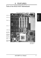
FEATURES (Parts of the ASUS HX97 Motherboard 4 ISA Slots 4 PCI Slots Floppy Conn. 2 IDE Conn. 4 SIMM Sockets Intel's 430HX PCIset Programmable Flash ROM IrDA Connect. FEATURES Parts of Board) II. II. CPU ZIF Socket 7 Switching Voltage Regulators PS/2 Mouse, USB, IrDA Super Multi-I/O PS/2 Mouse Serial, Parallel, Floppy 256/512KB Pipelined Burst L2 Cache ASUS HX97 User's Manual 9
FEATURES (Parts of the ASUS HX97 Motherboard 4 ISA Slots 4 PCI Slots Floppy Conn. 2 IDE Conn. 4 SIMM Sockets Intel's 430HX PCIset Programmable Flash ROM IrDA Connect. FEATURES Parts of Board) II. II. CPU ZIF Socket 7 Switching Voltage Regulators PS/2 Mouse, USB, IrDA Super Multi-I/O PS/2 Mouse Serial, Parallel, Floppy 256/512KB Pipelined Burst L2 Cache ASUS HX97 User's Manual 9
User Manual
Page 10
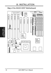
... FS0 VID2 VID1 VID0 Flash BIOS IDE (HD) LED RTC Clear Infrared Panel Connectors CPU Voltage Switching Voltage Regulators 10 III. INSTALLATION (Map of the ASUS HX97 Motherboard SIMM Socket 4 (32-bit, 72-pin module) SIMM Socket 3 (32-bit, 72-pin module) SIMM Socket 2 (32-bit, 72-pin module) SIMM Socket 1 (32... 7 CPU Fan BF0 BF1 Freq. 256/512KB Pipelined Burst L2 Cache Row 0 1 0 1 2 3 2 3 Intel 430HX PCIset Parallel (Printer) Port AT Keyboard Connector PS/2 Mouse Serial Ports ASUS HX97 User's Manual III. INSTALLATION Map of Board)
... FS0 VID2 VID1 VID0 Flash BIOS IDE (HD) LED RTC Clear Infrared Panel Connectors CPU Voltage Switching Voltage Regulators 10 III. INSTALLATION (Map of the ASUS HX97 Motherboard SIMM Socket 4 (32-bit, 72-pin module) SIMM Socket 3 (32-bit, 72-pin module) SIMM Socket 2 (32-bit, 72-pin module) SIMM Socket 1 (32... 7 CPU Fan BF0 BF1 Freq. 256/512KB Pipelined Burst L2 Cache Row 0 1 0 1 2 3 2 3 Intel 430HX PCIset Parallel (Printer) Port AT Keyboard Connector PS/2 Mouse Serial Ports ASUS HX97 User's Manual III. INSTALLATION Map of Board)
User Manual
Page 11
... Speaker Output Connector (4-pins) p. 28 CPU Cooling Fan Power Lead (3-pin Block) p. 29 Motherboard Power Connector (12-pin Block) III. III. INSTALLATION (Map of Board) ASUS HX97 User's Manual 11
... Speaker Output Connector (4-pins) p. 28 CPU Cooling Fan Power Lead (3-pin Block) p. 29 Motherboard Power Connector (12-pin Block) III. III. INSTALLATION (Map of Board) ASUS HX97 User's Manual 11

User Manual
Page 12
Set Jumpers on the bag that both jumpers be sharing pins from the system. 12 ASUS HX97 User's Manual Install the Central Processing Unit (CPU) 4. Pin 1 Pin 1 tively. To connect the pins, simply place a plastic jumper cap over the two pins as to ... on page 4 for Open (Off). Settings with two jumper numbers require that came with three pins. Setup the BIOS Software 1. Use the diagrams in this manual instead of the Motherboard" on the inside. 2. Unplug your computer. 1. See "Map of following steps: 1. Install DRAM Modules 3. tions of jumper caps to ...
Set Jumpers on the bag that both jumpers be sharing pins from the system. 12 ASUS HX97 User's Manual Install the Central Processing Unit (CPU) 4. Pin 1 Pin 1 tively. To connect the pins, simply place a plastic jumper cap over the two pins as to ... on page 4 for Open (Off). Settings with two jumper numbers require that came with three pins. Setup the BIOS Software 1. Use the diagrams in this manual instead of the Motherboard" on the inside. 2. Unplug your computer. 1. See "Map of following steps: 1. Install DRAM Modules 3. tions of jumper caps to ...
User Manual
Page 13
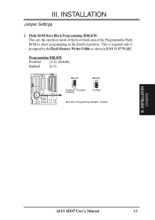
Flash ROM Boot Block Programming (BBLKW) This sets the operation mode of the boot block area of the Programmable Flash ROM to allow programming in BIOS SOFTWARE. III. INSTALLATION (Jumpers) ASUS HX97 User's Manual 13 Programming BBLKW Disabled [1-2] (Default) Enabled [2-3] R BBLKW 1 2 3 Disabled / Protected (Default) BBLKW 1 2 3 Enabled Boot Block Programming (Disable / Enable) III. INSTALLATION Jumper Settings 1. This is required only if prompted by the Flash Memory Writer Utility as shown in the Enabled position.
Flash ROM Boot Block Programming (BBLKW) This sets the operation mode of the boot block area of the Programmable Flash ROM to allow programming in BIOS SOFTWARE. III. INSTALLATION (Jumpers) ASUS HX97 User's Manual 13 Programming BBLKW Disabled [1-2] (Default) Enabled [2-3] R BBLKW 1 2 3 Disabled / Protected (Default) BBLKW 1 2 3 Enabled Boot Block Programming (Disable / Enable) III. INSTALLATION Jumper Settings 1. This is required only if prompted by the Flash Memory Writer Utility as shown in the Enabled position.

User Manual
Page 14
... Defaults" and re-enter any user information after removing and reapplying this action. You should enter BIOS to reenter user preferences. INSTALLATION (Jumpers) 14 ASUS HX97 User's Manual The CMOS RAM containing BIOS setup information may be cleared by the onboard button cell battery. Battery Test Jumper (For Service Use Only) You can...
... Defaults" and re-enter any user information after removing and reapplying this action. You should enter BIOS to reenter user preferences. INSTALLATION (Jumpers) 14 ASUS HX97 User's Manual The CMOS RAM containing BIOS setup information may be cleared by the onboard button cell battery. Battery Test Jumper (For Service Use Only) You can...
User Manual
Page 15
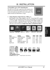
.../CS/M1 (VRE3.5V) P54C/CS (STD3.4V) AMDK6-P6166, P55C MMC/ AMDK6-233 (3.2V) PR200 (2.9V) Cyrix M2 (2.8V) Voltage Regulator Output Selection ASUS HX97 User's Manual 15 Voltage Regulator Output Selection (VID0, 1, 2) These jumpers set the voltage supplied to the CPU. Current Intel CPU's marked "Pentium" has only a Single Power Plane...
.../CS/M1 (VRE3.5V) P54C/CS (STD3.4V) AMDK6-P6166, P55C MMC/ AMDK6-233 (3.2V) PR200 (2.9V) Cyrix M2 (2.8V) Voltage Regulator Output Selection ASUS HX97 User's Manual 15 Voltage Regulator Output Selection (VID0, 1, 2) These jumpers set the voltage supplied to the CPU. Current Intel CPU's marked "Pentium" has only a Single Power Plane...
User Manual
Page 16
... clock generator what frequency to send to BUS Frequency Ratio (BF0, BF1) These jumpers set together with the Cyrix 166+ installed on this motherboard. 16 ASUS HX97 User's Manual FS2 FS1 FS0 FS1 FS0 FS2 FS1 FS0 FS2 FS1 FS0 1 1 1 1 2 2 2 2 3 3 3 3 50MHz 55MHz 60MHz 66MHz CPU External Clock (BUS) Frequency Selection BF1 FS2 BF0...
... clock generator what frequency to send to BUS Frequency Ratio (BF0, BF1) These jumpers set together with the Cyrix 166+ installed on this motherboard. 16 ASUS HX97 User's Manual FS2 FS1 FS0 FS1 FS0 FS2 FS1 FS0 FS2 FS1 FS0 1 1 1 1 2 2 2 2 3 3 3 3 50MHz 55MHz 60MHz 66MHz CPU External Clock (BUS) Frequency Selection BF1 FS2 BF0...
User Manual
Page 17
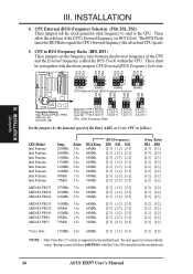
..., 8MB, 16MB, 32MB, 64MB (Rows 2 & 3) 72-pin FPM or EDO SIMM Total Memory x2 x2 Total System Memory (Max 256MB) = III. INSTALLATION (System Memory) ASUS HX97 User's Manual 17 The SIMMs can be unstable. To support ECC, you must be installed in pairs so that each Row (see Map of the memory subsystem...
..., 8MB, 16MB, 32MB, 64MB (Rows 2 & 3) 72-pin FPM or EDO SIMM Total Memory x2 x2 Total System Memory (Max 256MB) = III. INSTALLATION (System Memory) ASUS HX97 User's Manual 17 The SIMMs can be unstable. To support ECC, you must be installed in pairs so that each Row (see Map of the memory subsystem...
User Manual
Page 18
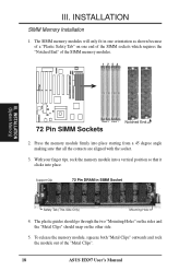
... through the two "Mounting Holes" on the sides and the "Metal Clips" should snap on one orientation as shown because of the "Metal Clips". 18 ASUS HX97 User's Manual INSTALLATION (System Memory) Bank 0 Bank 1 Notched End 72 Pin SIMM Sockets 2. With your finger tips, rock the memory module into place. To release the...
... through the two "Mounting Holes" on the sides and the "Metal Clips" should snap on one orientation as shown because of the "Metal Clips". 18 ASUS HX97 User's Manual INSTALLATION (System Memory) Bank 0 Bank 1 Notched End 72 Pin SIMM Sockets 2. With your finger tips, rock the memory module into place. To release the...
User Manual
Page 19
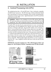
... point towards the end the of the CPU fan, no force is backwards compatible with Pentium Processor Lever Lock Blank Installed CPU Example White Dot ASUS HX97 User's Manual 19 Once completely inserted, hold down on your system. If this section.) To install a CPU, first turn on the fan and close the socket...
... point towards the end the of the CPU fan, no force is backwards compatible with Pentium Processor Lever Lock Blank Installed CPU Example White Dot ASUS HX97 User's Manual 19 Once completely inserted, hold down on your system. If this section.) To install a CPU, first turn on the fan and close the socket...

User Manual
Page 20
III. Remove your expansion card. Keep the bracket for expansion cards. 20 ASUS HX97 User's Manual Generally an IRQ must be required to one use . Failure to do so may be exclusively assigned to setup your power supply when adding or ...
III. Remove your expansion card. Keep the bracket for expansion cards. 20 ASUS HX97 User's Manual Generally an IRQ must be required to one use . Failure to do so may be exclusively assigned to setup your power supply when adding or ...


