
User Guide
Page 9
ix H170-PLUS D3 specifications summary Internal I/O connectors BIOS features Manageability Support DVD 2 x USB 3.0/2.0 connectors support additional 4 USB ports 2 x USB 2.0/1/1 connectors support additional 4 USB ports 1 x M.2 Socket 3 (for M ...(OEM version) OS support Form factor Windows® 10 64bit Windows® 8.1 64bit Windows® 7 32bit/64bit* * Please refer to ASUS website and download "Windows® 7 installation guide" and "ASUS EZ installer" to change without notice. ATX Form Factor, 12"x 8.6" (30.5cm x 21.8cm) Specifications are subject to install Windows® 7.
ix H170-PLUS D3 specifications summary Internal I/O connectors BIOS features Manageability Support DVD 2 x USB 3.0/2.0 connectors support additional 4 USB ports 2 x USB 2.0/1/1 connectors support additional 4 USB ports 1 x M.2 Socket 3 (for M ...(OEM version) OS support Form factor Windows® 10 64bit Windows® 8.1 64bit Windows® 7 32bit/64bit* * Please refer to ASUS website and download "Windows® 7 installation guide" and "ASUS EZ installer" to change without notice. ATX Form Factor, 12"x 8.6" (30.5cm x 21.8cm) Specifications are subject to install Windows® 7.
User Guide
Page 11
... screws into the holes indicated by circles to secure the motherboard to static electricity. • Before you physical injury and damage to ensure that the ATX power supply is switched off or the power cord is detached from the wall socket before installing or removing the motherboard. ASUS H170-PLUS D3 1-1
... screws into the holes indicated by circles to secure the motherboard to static electricity. • Before you physical injury and damage to ensure that the ATX power supply is switched off or the power cord is detached from the wall socket before installing or removing the motherboard. ASUS H170-PLUS D3 1-1
User Guide
Page 13
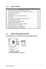
...connector (7-pin SATA6G_3~6) 8. System panel connector (20-5 pin PANEL) 10. Intel® LGA1151 CPU socket 4. M.2 Socket 3 7. Clear RTC RAM (2-pin CLRTC) 9. H170-PLUS D3 H170-PLUS D3 CPU socket LGA1151 ASUS H170-PLUS D3 1-3 Front panel audio connector (10-1 pin AAFP) Page 1-17 1-20 1-3 1-7 1-16 1-19 1-21 1-12 1-22 1-23 1-15 1-15 1-18 1-18 ...port connectors (10-1 pin COM) 13. USB 3.0 connector (20-1 pin USB3_12, USB3_34) 6. Digital audio connector (4-1 pin SPDIF_OUT) 14. ATX power connectors (24-pin EATXPWR, 8-pin ATX12V) 2. 1.2.4 Layout contents Connectors/Jumpers/Slots/LED 1.
...connector (7-pin SATA6G_3~6) 8. System panel connector (20-5 pin PANEL) 10. Intel® LGA1151 CPU socket 4. M.2 Socket 3 7. Clear RTC RAM (2-pin CLRTC) 9. H170-PLUS D3 H170-PLUS D3 CPU socket LGA1151 ASUS H170-PLUS D3 1-3 Front panel audio connector (10-1 pin AAFP) Page 1-17 1-20 1-3 1-7 1-16 1-19 1-21 1-12 1-22 1-23 1-15 1-15 1-18 1-18 ...port connectors (10-1 pin COM) 13. USB 3.0 connector (20-1 pin USB3_12, USB3_34) 6. Digital audio connector (4-1 pin SPDIF_OUT) 14. ATX power connectors (24-pin EATXPWR, 8-pin ATX12V) 2. 1.2.4 Layout contents Connectors/Jumpers/Slots/LED 1.

User Guide
Page 27
... additional devices. ASUS H170-PLUS D3 1-17 H170-PLUS D3 A A EATX12V B EATXPWR +12V DC +12V DC +12V DC +12V DC +3 Volts GND +12 Volts +5 Volts +12 Volts +5 Volts B +5V Standby +5 Volts Power OK -5 Volts GND PIN 1 +5 Volts GND GND GND GND GND GND GND GND +5 Volts PSON# GND GND +3 Volts -12 Volts +3 Volts +3 Volts PIN 1 H170-PLUS D3 ATX power connectors...
... additional devices. ASUS H170-PLUS D3 1-17 H170-PLUS D3 A A EATX12V B EATXPWR +12V DC +12V DC +12V DC +12V DC +3 Volts GND +12 Volts +5 Volts +12 Volts +5 Volts B +5V Standby +5 Volts Power OK -5 Volts GND PIN 1 +5 Volts GND GND GND GND GND GND GND GND +5 Volts PSON# GND GND +3 Volts -12 Volts +3 Volts +3 Volts PIN 1 H170-PLUS D3 ATX power connectors...

User Guide
Page 32
...for system reboot without turning off button (2-pin PWR_SW) This connector is for the HDD Activity LED. Ground RESET NC PLED+ PLED- H170-PLUS D3 PIN 1 +HDD_LED- The system power LED lights up or flashes when data is read from or written to this connector. PANEL +PWR_LED... (4-pin SPEAKER) This 4-pin connector is for the chassis-mounted reset button for the system power button. RESET +PWR_LED* Requires an ATX power supply H170-PLUS D3 System panel connector • System power LED (4-pin +PWR_LED-) This 2-pin connector is for the chassis-mounted system warning speaker. System...
...for system reboot without turning off button (2-pin PWR_SW) This connector is for the HDD Activity LED. Ground RESET NC PLED+ PLED- H170-PLUS D3 PIN 1 +HDD_LED- The system power LED lights up or flashes when data is read from or written to this connector. PANEL +PWR_LED... (4-pin SPEAKER) This 4-pin connector is for the chassis-mounted reset button for the system power button. RESET +PWR_LED* Requires an ATX power supply H170-PLUS D3 System panel connector • System power LED (4-pin +PWR_LED-) This 2-pin connector is for the chassis-mounted system warning speaker. System...

