User Guide
Page 6
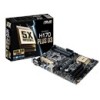
Please refer to www.asus.com for Intel® CPU support list. H170-PLUS D3 specifications summary CPU Chipset Memory Graphics Expansion Slots LGA1151 socket for Intel® 6th Generation Core™ i7 / i5 / i3, Pentium®, and ... slots 2 x PCI slots (continued on the CPU types. ** Refer to Memory QVL (Qualified Vendors List) for the following items. Motherboard Cables Accessories Application DVD Documentation ASUS H170-PLUS D3 motherboard 2 x Serial ATA 6.0 Gb/s cables 1 x I/O Shield 1 x M.2 screw package Support DVD User Guide If any of the above items is subject to the ...
Please refer to www.asus.com for Intel® CPU support list. H170-PLUS D3 specifications summary CPU Chipset Memory Graphics Expansion Slots LGA1151 socket for Intel® 6th Generation Core™ i7 / i5 / i3, Pentium®, and ... slots 2 x PCI slots (continued on the CPU types. ** Refer to Memory QVL (Qualified Vendors List) for the following items. Motherboard Cables Accessories Application DVD Documentation ASUS H170-PLUS D3 motherboard 2 x Serial ATA 6.0 Gb/s cables 1 x I/O Shield 1 x M.2 screw package Support DVD User Guide If any of the above items is subject to the ...
User Guide
Page 11
... the holes indicated by circles to secure the motherboard to static electricity. • Before you install or remove any component, ensure that the motherboard fits. ASUS H170-PLUS D3 1-1 The edge with external ports goes to the rear part of the chassis as the power supply case, to avoid damaging them due to the...
... the holes indicated by circles to secure the motherboard to static electricity. • Before you install or remove any component, ensure that the motherboard fits. ASUS H170-PLUS D3 1-1 The edge with external ports goes to the rear part of the chassis as the power supply case, to avoid damaging them due to the...
User Guide
Page 13
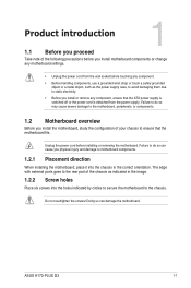
...~6) 8. USB 2.0 connectors (10-1 pin USB1112, USB1314) 12. Intel® LGA1151 CPU socket 4. Standby power LED (SB_PWR) 11. M.2 Socket 3 7. Clear RTC RAM (2-pin CLRTC) 9. H170-PLUS D3 H170-PLUS D3 CPU socket LGA1151 ASUS H170-PLUS D3 1-3 Front panel audio connector (10-1 pin AAFP) Page 1-17 1-20 1-3 1-7 1-16 1-19 1-21 1-12 1-22 1-23 1-15 1-15 1-18 1-18 1.3 Central Processing Unit (CPU...
...~6) 8. USB 2.0 connectors (10-1 pin USB1112, USB1314) 12. Intel® LGA1151 CPU socket 4. Standby power LED (SB_PWR) 11. M.2 Socket 3 7. Clear RTC RAM (2-pin CLRTC) 9. H170-PLUS D3 H170-PLUS D3 CPU socket LGA1151 ASUS H170-PLUS D3 1-3 Front panel audio connector (10-1 pin AAFP) Page 1-17 1-20 1-3 1-7 1-16 1-19 1-21 1-12 1-22 1-23 1-15 1-15 1-18 1-18 1.3 Central Processing Unit (CPU...

User Guide
Page 15
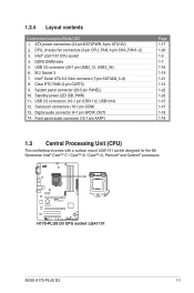
ASUS H170-PLUS D3 1-5 4 C 5 A B 1.3.2 CPU heatsink and fan assembly installation Apply the Thermal Interface Material to the CPU heatsink and CPU before you install the heatsink and fan if necessary.
ASUS H170-PLUS D3 1-5 4 C 5 A B 1.3.2 CPU heatsink and fan assembly installation Apply the Thermal Interface Material to the CPU heatsink and CPU before you install the heatsink and fan if necessary.
User Guide
Page 17
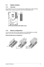
The figure illustrates the location of the DDR3 DIMM sockets: H170-PLUS D3 H170-PLUS D3 240-pin DDR3 DIMM sockets 1.4.2 Memory configurations You may install 2 GB, 4 GB, and 8 GB unbuffered non-ECC DDR3 DIMMs into the DIMM sockets. Recommended memory configurations ASUS H170-PLUS D3 1-7 You can refer to the recommended memory population below. DIMM_A1 DIMM_A2 DIMM_B1 DIMM_B2 1.4 System memory 1.4.1 Overview This motherboard comes with four Double Data Rate 3 (DDR3) Dual Inline Memory Module (DIMM) sockets.
The figure illustrates the location of the DDR3 DIMM sockets: H170-PLUS D3 H170-PLUS D3 240-pin DDR3 DIMM sockets 1.4.2 Memory configurations You may install 2 GB, 4 GB, and 8 GB unbuffered non-ECC DDR3 DIMMs into the DIMM sockets. Recommended memory configurations ASUS H170-PLUS D3 1-7 You can refer to the recommended memory population below. DIMM_A1 DIMM_A2 DIMM_B1 DIMM_B2 1.4 System memory 1.4.1 Overview This motherboard comes with four Double Data Rate 3 (DDR3) Dual Inline Memory Module (DIMM) sockets.

User Guide
Page 19
1.4.3 Installing a DIMM 1 2 3 To remove a DIMM B A ASUS H170-PLUS D3 1-9
1.4.3 Installing a DIMM 1 2 3 To remove a DIMM B A ASUS H170-PLUS D3 1-9

User Guide
Page 21
IRQ assignments for better thermal environment. shared shared - - - shared - - - shared - ASUS H170-PLUS D3 1-11 shared - - - - shared - - - - - shared - - - - shared - - - shared - - - - VGA configuration Single VGA/PCIe card Dual VGA/PCIe cards PCI Express operating mode PCIe 3.0 x16_1 (gray) x16 (Recommended ...
IRQ assignments for better thermal environment. shared shared - - - shared - - - shared - ASUS H170-PLUS D3 1-11 shared - - - - shared - - - - - shared - - - - shared - - - shared - - - - VGA configuration Single VGA/PCIe card Dual VGA/PCIe cards PCI Express operating mode PCIe 3.0 x16_1 (gray) x16 (Recommended ...

User Guide
Page 23
... indications Activity/Link LED Status Description Off No link Orange Linked Orange (Blinking) Data activity Orange Ready to a Local Area Network (LAN) through a network hub. ASUS H170-PLUS D3 1-13 This port allows Gigabit connection to (Blinking then wake up from steady) S5 mode Speed LED Status Description OFF 10Mbps connection ORANGE 100Mbps connection...
... indications Activity/Link LED Status Description Off No link Orange Linked Orange (Blinking) Data activity Orange Ready to a Local Area Network (LAN) through a network hub. ASUS H170-PLUS D3 1-13 This port allows Gigabit connection to (Blinking then wake up from steady) S5 mode Speed LED Status Description OFF 10Mbps connection ORANGE 100Mbps connection...

User Guide
Page 25
... so will damage the motherboard! USB1112 USB1314 USB+5V USB_P13USB_P13+ GND NC USB+5V USB_P11USB_P11+ GND NC H170-PLUS D3 PIN 1 PIN 1 USB+5V USB_P14USB_P14+ GND USB+5V USB_P12USB_P12+ GND H170-PLUS D3 USB2.0 connectors Never connect a 1394 cable to 480Mbps connection speed. RXD DTR DSR CTS DCD TXD GND... at the back of the system chassis. These USB connectors comply with USB 2.0 specifications and supports up to the USB connectors. ASUS H170-PLUS D3 1-15 Connect the USB module cable to any of these connectors, then install the module to a slot opening at the back ...
... so will damage the motherboard! USB1112 USB1314 USB+5V USB_P13USB_P13+ GND NC USB+5V USB_P11USB_P11+ GND NC H170-PLUS D3 PIN 1 PIN 1 USB+5V USB_P14USB_P14+ GND USB+5V USB_P12USB_P12+ GND H170-PLUS D3 USB2.0 connectors Never connect a 1394 cable to 480Mbps connection speed. RXD DTR DSR CTS DCD TXD GND... at the back of the system chassis. These USB connectors comply with USB 2.0 specifications and supports up to the USB connectors. ASUS H170-PLUS D3 1-15 Connect the USB module cable to any of these connectors, then install the module to a slot opening at the back ...

User Guide
Page 27
com/PowerSupplyCalculator/PSCalculator.aspx?SLanguage=en-us for ATX power supply plugs. ASUS H170-PLUS D3 1-17 The power supply plugs are for details. H170-PLUS D3 A A EATX12V B EATXPWR +12V DC +12V DC +12V DC +12V DC +3 Volts GND +12 Volts +5 Volts +12 Volts +5 Volts B +5V ... 1 +5 Volts GND GND GND GND GND GND GND GND +5 Volts PSON# GND GND +3 Volts -12 Volts +3 Volts +3 Volts PIN 1 H170-PLUS D3 ATX power connectors • For a fully configured system, we recommend that complies with more power-consuming devices or when you intend to the Recommended Power...
com/PowerSupplyCalculator/PSCalculator.aspx?SLanguage=en-us for ATX power supply plugs. ASUS H170-PLUS D3 1-17 The power supply plugs are for details. H170-PLUS D3 A A EATX12V B EATXPWR +12V DC +12V DC +12V DC +12V DC +3 Volts GND +12 Volts +5 Volts +12 Volts +5 Volts B +5V ... 1 +5 Volts GND GND GND GND GND GND GND GND +5 Volts PSON# GND GND +3 Volts -12 Volts +3 Volts +3 Volts PIN 1 H170-PLUS D3 ATX power connectors • For a fully configured system, we recommend that complies with more power-consuming devices or when you intend to the Recommended Power...

User Guide
Page 29
H170-PLUS D3 M.2(SOCKET3) H170-PLUS D3 M.2(SOCKET3) • This socket supports M Key and 2242/2260/2280 storage devices. • When using Intel® Desktop Responsiveness technologies with PCIe/SATA M.2 device, ensure to install an M.2 (NGFF) SSD module. The M.2 (NGFF) SSD module is purchased separately. ASUS H170-PLUS D3 1-19 M.2 socket 3 This socket allows you to set up the Windows® UEFI operating system under RAID mode. 7.
H170-PLUS D3 M.2(SOCKET3) H170-PLUS D3 M.2(SOCKET3) • This socket supports M Key and 2242/2260/2280 storage devices. • When using Intel® Desktop Responsiveness technologies with PCIe/SATA M.2 device, ensure to install an M.2 (NGFF) SSD module. The M.2 (NGFF) SSD module is purchased separately. ASUS H170-PLUS D3 1-19 M.2 socket 3 This socket allows you to set up the Windows® UEFI operating system under RAID mode. 7.

User Guide
Page 31
... SATA6G_6 SATA6G_5 GND RSATA_TXP3 RSATA_TXN3 GND RSATA_RXN3 RSATA_RXP3 GND GND RSATA_TXP4 RSATA_TXN4 GND RSATA_RXN4 RSATA_RXP4 GND H170-PLUS D3 Intel® SATA 6.0Gb/s connectors When using hot-plug and NCQ, set the SATA Mode Selection item in the BIOS to Serial ATA 6.0 Gb/s hard disk drives via Serial ATA 6.0 Gb/s signal cables. ASUS H170-PLUS D3 1-21
... SATA6G_6 SATA6G_5 GND RSATA_TXP3 RSATA_TXN3 GND RSATA_RXN3 RSATA_RXP3 GND GND RSATA_TXP4 RSATA_TXN4 GND RSATA_RXN4 RSATA_RXP4 GND H170-PLUS D3 Intel® SATA 6.0Gb/s connectors When using hot-plug and NCQ, set the SATA Mode Selection item in the BIOS to Serial ATA 6.0 Gb/s hard disk drives via Serial ATA 6.0 Gb/s signal cables. ASUS H170-PLUS D3 1-21
User Guide
Page 33
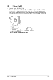
This is a reminder that the system is ON, in sleep mode, or in any motherboard component. Standby Power LED (SB_PWR) The motherboard comes with a standby power LED that lights up to indicate that you should shut down the system and unplug the power cable before removing or plugging in soft-off mode. The illustration below shows the location of the onboard LED. H170-PLUS D3 SB_PWR ON OFF Standby Power Powered Off H170-PLUS D3 Standby power LED ASUS H170-PLUS D3 1-23 1.8 Onboard LED 1.
This is a reminder that the system is ON, in sleep mode, or in any motherboard component. Standby Power LED (SB_PWR) The motherboard comes with a standby power LED that lights up to indicate that you should shut down the system and unplug the power cable before removing or plugging in soft-off mode. The illustration below shows the location of the onboard LED. H170-PLUS D3 SB_PWR ON OFF Standby Power Powered Off H170-PLUS D3 Standby power LED ASUS H170-PLUS D3 1-23 1.8 Onboard LED 1.
User Guide
Page 35
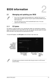
ASUS H170-PLUS D3 2-1 Copy the original motherboard BIOS using the ASUS Update utility. • The screen captures are for reference only. 2.1.1 EZ Update EZ Update is a utility that allows you can also manually update the saved ... to automatically update your motherboard's driver, software and firmware Click to restore the BIOS in case you need to find and select the BIOS from H170-PLUS D3 BIOS 0307 version. BIOS information 2 2.1 Managing and updating your BIOS • Save a copy of the original motherboard BIOS file to a USB flash disk in the...
ASUS H170-PLUS D3 2-1 Copy the original motherboard BIOS using the ASUS Update utility. • The screen captures are for reference only. 2.1.1 EZ Update EZ Update is a utility that allows you can also manually update the saved ... to automatically update your motherboard's driver, software and firmware Click to restore the BIOS in case you need to find and select the BIOS from H170-PLUS D3 BIOS 0307 version. BIOS information 2 2.1 Managing and updating your BIOS • Save a copy of the original motherboard BIOS file to a USB flash disk in the...
User Guide
Page 37
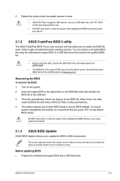
.... Before updating BIOS • Prepare the motherboard support DVD and a USB flash drive. Recovering the BIOS To recover the BIOS: 1. ASUS H170-PLUS D3 2-3 The utility automatically checks the devices for reference only and may not be exactly the same as a USB flash disk, with FAT... environment. To ensure system compatibility and stability, we recommend that contains the BIOS file to prevent system boot failure! 2.1.3 ASUS CrashFree BIOS 3 utility The ASUS CrashFree BIOS 3 is an auto recovery tool that contains the updated BIOS file. • Before using the motherboard support ...
.... Before updating BIOS • Prepare the motherboard support DVD and a USB flash drive. Recovering the BIOS To recover the BIOS: 1. ASUS H170-PLUS D3 2-3 The utility automatically checks the devices for reference only and may not be exactly the same as a USB flash disk, with FAT... environment. To ensure system compatibility and stability, we recommend that contains the BIOS file to prevent system boot failure! 2.1.3 ASUS CrashFree BIOS 3 utility The ASUS CrashFree BIOS 3 is an auto recovery tool that contains the updated BIOS file. • Before using the motherboard support ...

User Guide
Page 39
... BIOS to ensure system compatibility and stability. D:/> bupdater /pc /g 2. Ensure to load the BIOS default settings to prevent system boot failaure. ASUS H170-PLUS D3 2-5 After the BIOS Updater checks the selected BIOS file, select Yes to update the BIOS? See section 2.10 Exit Menu for DOS V1....31 [2014/01/01] Current ROM BOARD: H170-PLUS D3 VER: 0307 (H :00 B :00) DATE: 12/27/2089 PATH: C:\ Update ROM BOARD: Unknown VER: Unknown DATE: Unknown C: FORMAN~1 D: H17P3...
... BIOS to ensure system compatibility and stability. D:/> bupdater /pc /g 2. Ensure to load the BIOS default settings to prevent system boot failaure. ASUS H170-PLUS D3 2-5 After the BIOS Updater checks the selected BIOS file, select Yes to update the BIOS? See section 2.10 Exit Menu for DOS V1....31 [2014/01/01] Current ROM BOARD: H170-PLUS D3 VER: 0307 (H :00 B :00) DATE: 12/27/2089 PATH: C:\ Update ROM BOARD: Unknown VER: Unknown DATE: Unknown C: FORMAN~1 D: H17P3...
User Guide
Page 41
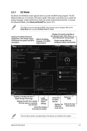
... Advanced device priority mode menus The boot device options vary depending on the devices you installed to Selects the display language of the selected mode. ASUS H170-PLUS D3 2-7 Click to the system. Refer to the Setup Mode item in section 2.8 Boot menu for entering the BIOS setup program can be changed...
... Advanced device priority mode menus The boot device options vary depending on the devices you installed to Selects the display language of the selected mode. ASUS H170-PLUS D3 2-7 Click to the system. Refer to the Setup Mode item in section 2.8 Boot menu for entering the BIOS setup program can be changed...

User Guide
Page 43
To display the submenu, select the item and press . ASUS H170-PLUS D3 2-9 Click this button to manually tweak the fans to view and tweak the overclocking settings of your system. MyFavorites (F3) This button above the menu ...
To display the submenu, select the item and press . ASUS H170-PLUS D3 2-9 Click this button to manually tweak the fans to view and tweak the overclocking settings of your system. MyFavorites (F3) This button above the menu ...

User Guide
Page 45
Click to select a fan to be configured Select a profile to apply to your fans Click to undo the changes Click to apply the fan setting Click to go back to set a fan profile or manually configure the operating speed of your CPU and chassis fans. 2.2.3 QFan Control The QFan Control allows you to main menu ASUS H170-PLUS D3 2-11
Click to select a fan to be configured Select a profile to apply to your fans Click to undo the changes Click to apply the fan setting Click to go back to set a fan profile or manually configure the operating speed of your CPU and chassis fans. 2.2.3 QFan Control The QFan Control allows you to main menu ASUS H170-PLUS D3 2-11

User Guide
Page 47
Click Yes to easily set RAID in your system using this feature. ASUS H170-PLUS D3 2-13 2.2.4 EZ Tuning Wizard EZ Tuning Wizard allows you to enable RAID. from the BIOS screen to open • Ensure that your HDDs have no existing RAID volumes. • Ensure to connect your keyboard or click EZ Tuning Wizard screen. 2. Press on your HDDs to continue. The available HDDs display. Click Next to Intel® SATA connectors. 3. Creating RAID To create RAID: 1.
Click Yes to easily set RAID in your system using this feature. ASUS H170-PLUS D3 2-13 2.2.4 EZ Tuning Wizard EZ Tuning Wizard allows you to enable RAID. from the BIOS screen to open • Ensure that your HDDs have no existing RAID volumes. • Ensure to connect your keyboard or click EZ Tuning Wizard screen. 2. Press on your HDDs to continue. The available HDDs display. Click Next to Intel® SATA connectors. 3. Creating RAID To create RAID: 1.


