User Guide
Page 13
ASUS ESC1000 G2 Product introduction Chapter 1 This chapter describes the general features of the workstation, including sections on front panel and rear panel specifications.
ASUS ESC1000 G2 Product introduction Chapter 1 This chapter describes the general features of the workstation, including sections on front panel and rear panel specifications.

User Guide
Page 15
Model Name ESC1000 G2 Processor / System Bus 1 x Socket LGA2011 Intel® Xeon® processor E5-1600/Core™ i7-3900/3800 processor family Core Logic (TDP=130W) Intel® ... for North America 2 x USB 3.0 ports 2 x USB 2.0 ports 1 x Line In 1 x Line Out (continued on the next page) ASUS ESC1000 G2 1-3 1.3 System specifications ASUS ESC1000 G2 is a workstation that features the ASUS P9X79 WS motherboard, supports Intel® LGA2011 Xeon® E5-1600/Core™ i7-3900/3800 series processors, and the latest technologies through the onboard ...
Model Name ESC1000 G2 Processor / System Bus 1 x Socket LGA2011 Intel® Xeon® processor E5-1600/Core™ i7-3900/3800 processor family Core Logic (TDP=130W) Intel® ... for North America 2 x USB 3.0 ports 2 x USB 2.0 ports 1 x Line In 1 x Line Out (continued on the next page) ASUS ESC1000 G2 1-3 1.3 System specifications ASUS ESC1000 G2 is a workstation that features the ASUS P9X79 WS motherboard, supports Intel® LGA2011 Xeon® E5-1600/Core™ i7-3900/3800 series processors, and the latest technologies through the onboard ...
User Guide
Page 17
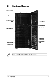
1.4 Front panel features HDD access LED Power LED Optical drive Empty 5.25-inch bays 4-bay HDD cage USB 2.0 ports USB 3.0 ports Security lock Power button Reset button Headphone output jack Microphone jack Refer to section 1.7.1 Front panel LEDs for the LED descriptions. ASUS ESC1000 G2 1-5
1.4 Front panel features HDD access LED Power LED Optical drive Empty 5.25-inch bays 4-bay HDD cage USB 2.0 ports USB 3.0 ports Security lock Power button Reset button Headphone output jack Microphone jack Refer to section 1.7.1 Front panel LEDs for the LED descriptions. ASUS ESC1000 G2 1-5
User Guide
Page 19
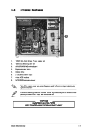
... ODD to use a floppy disk or an optical disc. *WARNING HAZARDOUS MOVING PARTS KEEP FINGERS AND OTHER BODY PARTS AWAY ASUS ESC1000 G2 1-7 Optical drive 6. 2 x 5.25-inch drive bays 7. 4-bay HDD module 8. ASUS P9X79 WS motherboard 4. SATA/SAS backplane board Turn off the system power and detach the power supply before removing or replacing...
... ODD to use a floppy disk or an optical disc. *WARNING HAZARDOUS MOVING PARTS KEEP FINGERS AND OTHER BODY PARTS AWAY ASUS ESC1000 G2 1-7 Optical drive 6. 2 x 5.25-inch drive bays 7. 4-bay HDD module 8. ASUS P9X79 WS motherboard 4. SATA/SAS backplane board Turn off the system power and detach the power supply before removing or replacing...

User Guide
Page 21
Hardware setup Chapter 2 This chapter lists the hardware setup procedures that you have to perform when installing or removing system components. ASUS ESC1000 G2
Hardware setup Chapter 2 This chapter lists the hardware setup procedures that you have to perform when installing or removing system components. ASUS ESC1000 G2
User Guide
Page 23
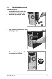
Match and insert the lower sliding edge of the side cover to the chassis. 3. Drive in place. 1 3 4. Position the side cover to the chassis edge. 2. 2.1.2 Reinstalling the side cover To reinstall the side cover: 1. Slide the side cover toward the front panel until it snaps in the two screws you removed earlier to secure the side cover. 4 ASUS ESC1000 G2 4 2-3
Match and insert the lower sliding edge of the side cover to the chassis. 3. Drive in place. 1 3 4. Position the side cover to the chassis edge. 2. 2.1.2 Reinstalling the side cover To reinstall the side cover: 1. Slide the side cover toward the front panel until it snaps in the two screws you removed earlier to secure the side cover. 4 ASUS ESC1000 G2 4 2-3
User Guide
Page 25
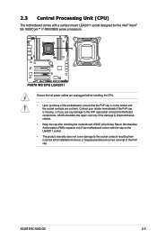
ASUS will process Return Merchandise Authorization (RMA) requests only if the motherboard comes with a surface mount LGA2011 socket designed for the Intel&#...cap is on the LGA2011 socket. • The product warranty does not cover damage to the PnP cap/socket contacts/motherboard components. ASUS shoulders the repair cost only if the damage is missing, or if you see any damage to the socket contacts resulting from incorrect CPU...PnP cap. Contact your retailer immediately if the PnP cap is shipment/transitrelated. • Keep the cap after installing the motherboard. ASUS ESC1000 G2 2-5
ASUS will process Return Merchandise Authorization (RMA) requests only if the motherboard comes with a surface mount LGA2011 socket designed for the Intel&#...cap is on the LGA2011 socket. • The product warranty does not cover damage to the PnP cap/socket contacts/motherboard components. ASUS shoulders the repair cost only if the damage is missing, or if you see any damage to the socket contacts resulting from incorrect CPU...PnP cap. Contact your retailer immediately if the PnP cap is shipment/transitrelated. • Keep the cap after installing the motherboard. ASUS ESC1000 G2 2-5
User Guide
Page 29
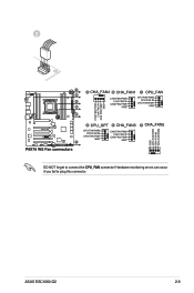
ASUS ESC1000 G2 2-9 Hardware monitoring errors can occur if you fail to connect the CPU_FAN connector! 2 ® DO NOT forget to plug this connector.
ASUS ESC1000 G2 2-9 Hardware monitoring errors can occur if you fail to connect the CPU_FAN connector! 2 ® DO NOT forget to plug this connector.
User Guide
Page 31
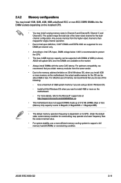
...memory from the same vendor. • Due to the memory address limitation on 32-bit Windows OS, when you do any of 8GB (or above). ASUS will update QVL once the DIMMs are available on the motherboard. - Under the default state, some memory modules for one DIMM per channel only. &#... the OS can be about 3GB or less. For effective use a more on the market. • Always install DIMMs with DIMMs of the following: - ASUS ESC1000 G2 2-11 Use a maximum of 3GB system memory if you want to install 4GB or more efficient memory cooling system to support a full memory load (8 DIMMs...
...memory from the same vendor. • Due to the memory address limitation on 32-bit Windows OS, when you do any of 8GB (or above). ASUS will update QVL once the DIMMs are available on the motherboard. - Under the default state, some memory modules for one DIMM per channel only. &#... the OS can be about 3GB or less. For effective use a more on the market. • Always install DIMMs with DIMMs of the following: - ASUS ESC1000 G2 2-11 Use a maximum of 3GB system memory if you want to install 4GB or more efficient memory cooling system to support a full memory load (8 DIMMs...
User Guide
Page 33
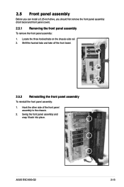
Swing the front panel assembly and snap it back into place. Locate the three hooked tabs on the chassis side rail. 2. Shift the hooked tabs and take off the front bezel. 2.5.2 Reinstalling the front panel assembly To reinstall the front panel assembly: 1. Hook the other side of the front panel assembly to the chassis. 2. ASUS ESC1000 G2 2-13 2.5 Front panel assembly Before you can install a 5.25-inch drive, you should first remove the front panel assembly (front bezel and front panel cover). 2.5.1 Removing the front panel assembly To remove the front panel assembly: 1.
Swing the front panel assembly and snap it back into place. Locate the three hooked tabs on the chassis side rail. 2. Shift the hooked tabs and take off the front bezel. 2.5.2 Reinstalling the front panel assembly To reinstall the front panel assembly: 1. Hook the other side of the front panel assembly to the chassis. 2. ASUS ESC1000 G2 2-13 2.5 Front panel assembly Before you can install a 5.25-inch drive, you should first remove the front panel assembly (front bezel and front panel cover). 2.5.1 Removing the front panel assembly To remove the front panel assembly: 1.
User Guide
Page 35
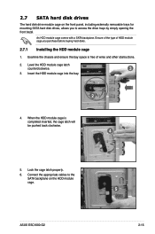
Lock the cage latch properly. 6. Connect the appropriate cables to access the drive trays by simply opening the front bezel. ASUS ESC1000 G2 5 2-15 Examine the chassis and ensure the bay space is completed inserted, the cage latch will be pushed back clockwise. 4 5. 2.7 SATA hard disk drives The ...
Lock the cage latch properly. 6. Connect the appropriate cables to access the drive trays by simply opening the front bezel. ASUS ESC1000 G2 5 2-15 Examine the chassis and ensure the bay space is completed inserted, the cage latch will be pushed back clockwise. 4 5. 2.7 SATA hard disk drives The ...
User Guide
Page 37
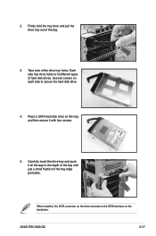
... connector on the drive connects to the SATA interface on the tray, and then secure it all the way to secure the hard disk drive. 4. ASUS ESC1000 G2 2-17 Carefully insert the drive tray and push it with four screws. 5. Place a SATA hard disk drive on the backplane. 2. Use two screws on each...
... connector on the drive connects to the SATA interface on the tray, and then secure it all the way to secure the hard disk drive. 4. ASUS ESC1000 G2 2-17 Carefully insert the drive tray and push it with four screws. 5. Place a SATA hard disk drive on the backplane. 2. Use two screws on each...
User Guide
Page 39
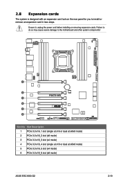
... slot (x4 mode) 4 PCIe 3.0 x16_4 slot (single at x16 or dual at x8/x8 mode) 5 PCIe 3.0 x16_5 slot (x4 mode) 6 PCIe 3.0 x16_6 slot (x8 mode) ASUS ESC1000 G2 2-19 Slot No. Failure to do so may cause severe damage to the motherboard and other system components!
... slot (x4 mode) 4 PCIe 3.0 x16_4 slot (single at x16 or dual at x8/x8 mode) 5 PCIe 3.0 x16_5 slot (x4 mode) 6 PCIe 3.0 x16_6 slot (x8 mode) ASUS ESC1000 G2 2-19 Slot No. Failure to do so may cause severe damage to the motherboard and other system components!

User Guide
Page 41
... for PCI Steering 10 5 IRQ Holder for PCI Steering 11 6 IRQ Holder for PCI Steering 12 7 Reserved 13 8 Numeric Data Processor 14 9 Primary IDE Channel ASUS ESC1000 G2 2-21 Restore the expansion card lock to the card. Refer to the following tables. 3. A light click indicates that the card is locked in place. 2.8.2 Configuring...
... for PCI Steering 10 5 IRQ Holder for PCI Steering 11 6 IRQ Holder for PCI Steering 12 7 Reserved 13 8 Numeric Data Processor 14 9 Primary IDE Channel ASUS ESC1000 G2 2-21 Restore the expansion card lock to the card. Refer to the following tables. 3. A light click indicates that the card is locked in place. 2.8.2 Configuring...
User Guide
Page 43
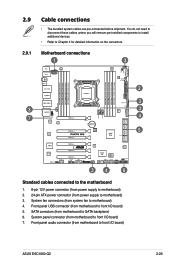
System panel connector (from motherboard to front I /O board) 5. Front panel audio connector (from motherboard to front I/O board) ASUS ESC1000 G2 2-23 You do not need to disconnect these cables unless you will remove pre‑installed components to install additional devices. • Refer to SATA ...
System panel connector (from motherboard to front I /O board) 5. Front panel audio connector (from motherboard to front I/O board) ASUS ESC1000 G2 2-23 You do not need to disconnect these cables unless you will remove pre‑installed components to install additional devices. • Refer to SATA ...
User Guide
Page 45
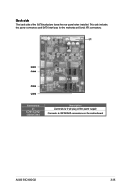
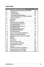
U1 CON1 CON2 CON4 CON3 Connectors U1 CON1/CON2/ CON3/CON4 Description Connects to SATA/SAS connectors on the motherboard ASUS ESC1000 G2 2-25 Back side The back side of the power supply Connects to 4-pin plug of the SATA backplane faces the rear panel when installed. This side includes the power connectors and SATA interfaces for the motherboard Serial ATA connectors.
U1 CON1 CON2 CON4 CON3 Connectors U1 CON1/CON2/ CON3/CON4 Description Connects to SATA/SAS connectors on the motherboard ASUS ESC1000 G2 2-25 Back side The back side of the power supply Connects to 4-pin plug of the SATA backplane faces the rear panel when installed. This side includes the power connectors and SATA interfaces for the motherboard Serial ATA connectors.
User Guide
Page 47
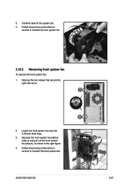
Remove the two screws that secure the right side cover. 1 2. ASUS ESC1000 G2 1 a b a 2-27 Squeeze the front system fan latches (step a) and pull out the front system fan (step b), as shown in reverse to reinstall the front system fan. Locate the front system fan near the 5.25-inch drive bays. 3. Follow the previous instructions in reverse to reinstall the rear system fan. 2.10.2 Removing front system fan To remove the front system fan: 1. Carefully take off the system fan. 4. Follow the previous instructions in the right figure. 4. 3.
Remove the two screws that secure the right side cover. 1 2. ASUS ESC1000 G2 1 a b a 2-27 Squeeze the front system fan latches (step a) and pull out the front system fan (step b), as shown in reverse to reinstall the front system fan. Locate the front system fan near the 5.25-inch drive bays. 3. Follow the previous instructions in reverse to reinstall the rear system fan. 2.10.2 Removing front system fan To remove the front system fan: 1. Carefully take off the system fan. 4. Follow the previous instructions in the right figure. 4. 3.

User Guide
Page 49
This chapter includes the motherboard layout, jumper settings, and connector locations. Motherboard Info Chapter 3 This chapter gives information about the motherboard that comes with the workstation. ASUS ESC1000 G2
This chapter includes the motherboard layout, jumper settings, and connector locations. Motherboard Info Chapter 3 This chapter gives information about the motherboard that comes with the workstation. ASUS ESC1000 G2
User Guide
Page 51
...) 21. Front panel audio connector (10-1 pin AAFP) Page 3-30 2-10 2-5 3-27 3-31 3-8 3-7 3-24 3-21 3-22 3-23 3-12 3-5 3-32 3-25 3-6 3-6 3-29 3-28 3-4 3-7 3-26 3-26 3-28 ASUS ESC1000 G2 3-3 CPU, CPU OPT, Chassis fan connectors (4-pin CPU_FAN, 4-pin CPU_OPT, 4-pin CHA_FAN1/2/3/4) 5. Q-Code LED (LED0, LED1) 13. Power-on button 18. Serial port connector (10...
...) 21. Front panel audio connector (10-1 pin AAFP) Page 3-30 2-10 2-5 3-27 3-31 3-8 3-7 3-24 3-21 3-22 3-23 3-12 3-5 3-32 3-25 3-6 3-6 3-29 3-28 3-4 3-7 3-26 3-26 3-28 ASUS ESC1000 G2 3-3 CPU, CPU OPT, Chassis fan connectors (4-pin CPU_FAN, 4-pin CPU_OPT, 4-pin CHA_FAN1/2/3/4) 5. Q-Code LED (LED0, LED1) 13. Power-on button 18. Serial port connector (10...
User Guide
Page 53
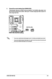
ASUS ESC1000 G2 3-5 2. The CHAFAN_SEL jumper is for fan pin selection. Set to pins 1-2 when using 3-pin fans or pins 2-3 when using 4-pin fans. ® • If you use a 3-pin fan but set the jumper for a 4-pin fan, the fan control will always run at full speed. Chassis Fan control setting (3-pin CHAFAN_SEL) These jumpers allow you installed will not work and the fan you to pin 1-2, the fan you installed may not work. • If you use a 4-pin fan but set the jumper to switch for the front fans and rear fans control.
ASUS ESC1000 G2 3-5 2. The CHAFAN_SEL jumper is for fan pin selection. Set to pins 1-2 when using 3-pin fans or pins 2-3 when using 4-pin fans. ® • If you use a 3-pin fan but set the jumper for a 4-pin fan, the fan control will always run at full speed. Chassis Fan control setting (3-pin CHAFAN_SEL) These jumpers allow you installed will not work and the fan you to pin 1-2, the fan you installed may not work. • If you use a 4-pin fan but set the jumper to switch for the front fans and rear fans control.


