User Guide
Page 5
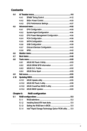
... Boot menu 4-48 4.8 Tools menu 4-50 4.8.1 ASUS EZ Flash 2 Utility 4-50 4.8.2 ASUS DRAM SPD Information 4-51 4.8.3 ASUS O.C. Profile 4-52 4.8.4 ASUS Drive Xpert 4-53 4.9 Exit menu 4-54 4.10 Updating BIOS 4-55 4.10.1 ASUS Update utility 4-55 4.10.2 ASUS EZ Flash 2 utility 4-58 4.10.3 ASUS CrashFree BIOS 3 utility 4-59 4.10.4 ASUS BIOS Updater 4-60 Chapter 5: RAID configuration 5.1 RAID configurations 5-2 5.1.1 RAID definitions 5-2 5.1.2 Installing Serial ATA hard disks 5-3 5.1.3 5.1.4 Setting the RAID item in BIOS 5-3 Intel® Rapid Storage Technology Option ROM utility...
... Boot menu 4-48 4.8 Tools menu 4-50 4.8.1 ASUS EZ Flash 2 Utility 4-50 4.8.2 ASUS DRAM SPD Information 4-51 4.8.3 ASUS O.C. Profile 4-52 4.8.4 ASUS Drive Xpert 4-53 4.9 Exit menu 4-54 4.10 Updating BIOS 4-55 4.10.1 ASUS Update utility 4-55 4.10.2 ASUS EZ Flash 2 utility 4-58 4.10.3 ASUS CrashFree BIOS 3 utility 4-59 4.10.4 ASUS BIOS Updater 4-60 Chapter 5: RAID configuration 5.1 RAID configurations 5-2 5.1.1 RAID definitions 5-2 5.1.2 Installing Serial ATA hard disks 5-3 5.1.3 5.1.4 Setting the RAID item in BIOS 5-3 Intel® Rapid Storage Technology Option ROM utility...
User Guide
Page 6
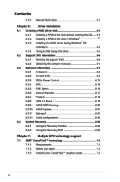
...Windows 6-2 Installing the RAID driver during Windows® OS installation 6-3 6.1.4 Using a USB floppy disk drive 6-3 6.2 Support DVD information 6-6 6.2.1 Running the support DVD 6-6 6.2.2 Obtaining the software manuals 6-7 6.3 Software information 6-8 6.3.1 AI Suite II 6-8 6.3.2 TurboV EVO 6-9 6.3.3 DIGI+ Power Control 6-13 6.3.4 EPU 6-15 6.3.5 FAN Xpert 6-16 6.3.6 Sensor Recorder 6-17 6.3.7 Probe II 6-18 6.3.8 USB 3.0 Boost 6-19 6.3.9 ASUS SSD Caching 6-20 6.3.10 ASUS Update 6-21 6.3.11 MyLogo2 6-22 6.3.12 Audio configurations 6-25 6.4 System Recovery...
...Windows 6-2 Installing the RAID driver during Windows® OS installation 6-3 6.1.4 Using a USB floppy disk drive 6-3 6.2 Support DVD information 6-6 6.2.1 Running the support DVD 6-6 6.2.2 Obtaining the software manuals 6-7 6.3 Software information 6-8 6.3.1 AI Suite II 6-8 6.3.2 TurboV EVO 6-9 6.3.3 DIGI+ Power Control 6-13 6.3.4 EPU 6-15 6.3.5 FAN Xpert 6-16 6.3.6 Sensor Recorder 6-17 6.3.7 Probe II 6-18 6.3.8 USB 3.0 Boost 6-19 6.3.9 ASUS SSD Caching 6-20 6.3.10 ASUS Update 6-21 6.3.11 MyLogo2 6-22 6.3.12 Audio configurations 6-25 6.4 System Recovery...
User Guide
Page 10
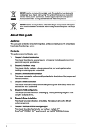
.... Chapter 2: Hardware setup This chapter lists the hardware setup procedures that the battery should not be placed in municipal waste. Chapter 3: Motherboard information This chapter includes the motherboard layout and brief descriptions of the server, including sections on front panel and rear panel specifications. 2. This product has been designed to change system settings through the BIOS Setup menus and describes the BIOS parameters. 5. Chapter 5: RAID configuration This chapter provides instructions for...
.... Chapter 2: Hardware setup This chapter lists the hardware setup procedures that the battery should not be placed in municipal waste. Chapter 3: Motherboard information This chapter includes the motherboard layout and brief descriptions of the server, including sections on front panel and rear panel specifications. 2. This product has been designed to change system settings through the BIOS Setup menus and describes the BIOS parameters. 5. Chapter 5: RAID configuration This chapter provides instructions for...
User Guide
Page 20
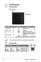
... Front panel LEDs HDD Access LED Power LED Drive Status LED LED Power LED Icon Display status Description ON System power ON HDD Access LED Drive status LED OFF Blinking No activity Read/write data into the HDD Green Bridge board connected to backplane Installed HDD is in good condition Red HDD failure Green/Red blinking HDD rebuilding using the RAID card The Power and HDD Access LEDs are visible even if the system front bezel is closed. 1.7.2 Rear panel LEDs Activity Link LED Status Description OFF No link ORANGE Linked BLINKING Data activity Speed LED Status...
... Front panel LEDs HDD Access LED Power LED Drive Status LED LED Power LED Icon Display status Description ON System power ON HDD Access LED Drive status LED OFF Blinking No activity Read/write data into the HDD Green Bridge board connected to backplane Installed HDD is in good condition Red HDD failure Green/Red blinking HDD rebuilding using the RAID card The Power and HDD Access LEDs are visible even if the system front bezel is closed. 1.7.2 Rear panel LEDs Activity Link LED Status Description OFF No link ORANGE Linked BLINKING Data activity Speed LED Status...

User Guide
Page 41
Install the software drivers for PCI Steering 12 7 Reserved 13 8 Numeric Data Processor 14 9 Primary IDE Channel ASUS ESC1000 G2 2-21 Programmable Interrupt 4 12 Communications Port (COM1) 5 13 IRQ Holder for PCI Steering 6 14 Reserved 7 15 Reserved 8 3 System CMOS/Real Time Clock 9 4 IRQ Holder for PCI Steering 10 5 IRQ Holder for PCI Steering 11 6 IRQ Holder for the expansion card. Standard interrupt assignments IRQ Priority Standard function...
Install the software drivers for PCI Steering 12 7 Reserved 13 8 Numeric Data Processor 14 9 Primary IDE Channel ASUS ESC1000 G2 2-21 Programmable Interrupt 4 12 Communications Port (COM1) 5 13 IRQ Holder for PCI Steering 6 14 Reserved 7 15 Reserved 8 3 System CMOS/Real Time Clock 9 4 IRQ Holder for PCI Steering 10 5 IRQ Holder for PCI Steering 11 6 IRQ Holder for the expansion card. Standard interrupt assignments IRQ Priority Standard function...
User Guide
Page 63
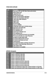
... No Console Input Devices are not available PCI resource allocation error. Interrupt controller is in PIC mode. ASUS ESC1000 G2 3-15 CF D0 D1 D2 D3 D4 D5 D6 D7 D8 D9 DA DB DC Description Reserved for ASL (see ASL Status Codes section below) Ready To Boot event Legacy Boot event Exit Boot Services event Runtime Set Virtual Address MAP Begin Runtime Set Virtual Address MAP End Legacy Option ROM Initialization System Reset USB hot plug PCI bus hot plug...
... No Console Input Devices are not available PCI resource allocation error. Interrupt controller is in PIC mode. ASUS ESC1000 G2 3-15 CF D0 D1 D2 D3 D4 D5 D6 D7 D8 D9 DA DB DC Description Reserved for ASL (see ASL Status Codes section below) Ready To Boot event Legacy Boot event Exit Boot Services event Runtime Set Virtual Address MAP Begin Runtime Set Virtual Address MAP End Legacy Option ROM Initialization System Reset USB hot plug PCI bus hot plug...
User Guide
Page 84
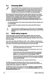
... support the bluetooth devices. BIOS (Basic Input and Output System) stores system hardware settings such as easy to "UEFI BIOS" unless otherwise specified. The BIOS setup program is designed to make it as storage device configuration, overclocking settings, advanced power management, and boot device configuration that are for reference purposes only, and may result to instability or failure to run the BIOS Setup. • You have installed a new system component that requires further BIOS settings or update...
... support the bluetooth devices. BIOS (Basic Input and Output System) stores system hardware settings such as easy to "UEFI BIOS" unless otherwise specified. The BIOS setup program is designed to make it as storage device configuration, overclocking settings, advanced power management, and boot device configuration that are for reference purposes only, and may result to instability or failure to run the BIOS Setup. • You have installed a new system component that requires further BIOS settings or update...
User Guide
Page 93
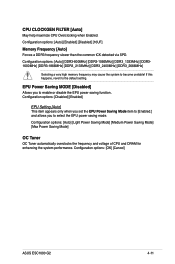
...! Configuration options: [Auto] [Enabled] [Disabled] [10UF] Memory Frequency [Auto] Forces a DDR3 frequency slower than the common tCK detected via SPD. Configuration options: [Auto] [DDR3-800MHz] [DDR3-1066MHz] [DDR3_1333MHz] [DDR31600MHz] [DDR3-1866MHz] [DDR3_2133MHz] [DDR3_2400MHz] [DDR3_2666MHz] Selecting a very high memory frequency may cause the system to the default setting. CPU CLOCKGEN FILTER [Auto] May help maximize CPU Overclocking when Enabled. Configuration options: [OK] [Cancel] ASUS ESC1000 G2 4-11...
...! Configuration options: [Auto] [Enabled] [Disabled] [10UF] Memory Frequency [Auto] Forces a DDR3 frequency slower than the common tCK detected via SPD. Configuration options: [Auto] [DDR3-800MHz] [DDR3-1066MHz] [DDR3_1333MHz] [DDR31600MHz] [DDR3-1866MHz] [DDR3_2133MHz] [DDR3_2400MHz] [DDR3_2666MHz] Selecting a very high memory frequency may cause the system to the default setting. CPU CLOCKGEN FILTER [Auto] May help maximize CPU Overclocking when Enabled. Configuration options: [OK] [Cancel] ASUS ESC1000 G2 4-11...
User Guide
Page 116
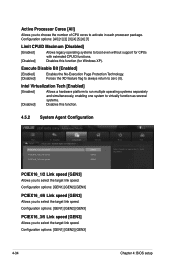
... operating systems to boot even without support for Windows XP). Configuration options: [GEN1] [GEN2] [GEN3] PCIEX16_3/5 Link speed [GEN3] Allows you to select the target link speed. Disables this function. 4.5.2 System Agent Configuration UEFI BIOS Utility - Active Processor Cores [All] Allows you to select the target link speed. Execute Disable Bit [Enabled] [Enabled] [Disabled] Enables the No-Execution Page Protection Technology. Advanced Mode Exit Main Back Ai Tweaker Advanced Advanced\ System Agent Configuration > Monitor PCIEX16_1/2 Link speed PCIEX16_4/8 Link...
... operating systems to boot even without support for Windows XP). Configuration options: [GEN1] [GEN2] [GEN3] PCIEX16_3/5 Link speed [GEN3] Allows you to select the target link speed. Disables this function. 4.5.2 System Agent Configuration UEFI BIOS Utility - Active Processor Cores [All] Allows you to select the target link speed. Execute Disable Bit [Enabled] [Enabled] [Disabled] Enables the No-Execution Page Protection Technology. Advanced Mode Exit Main Back Ai Tweaker Advanced Advanced\ System Agent Configuration > Monitor PCIEX16_1/2 Link speed PCIEX16_4/8 Link...
User Guide
Page 118
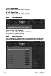
CPU C6 Report [Auto] Allows you to enable or disable the High Precision Event Timer. F1: General Help F2: Previous Values F3: Shortcut F5: Optimized Defaults F6: ASUS Ratio Boost F10: Save ESC: Exit F12: Print Screen 4-36 Chapter 4: BIOS setup Configuration options: [Disabled] [Enabled] 4.5.5 SATA Configuration While entering Setup, the BIOS automatically detects the presence of SATA devices. Status Check Enabled SATA 6G_1 (Gray) Hot Plug Not Present Disabled SATA 6G_2 (Gray) Hot Plug Not Present...
CPU C6 Report [Auto] Allows you to enable or disable the High Precision Event Timer. F1: General Help F2: Previous Values F3: Shortcut F5: Optimized Defaults F6: ASUS Ratio Boost F10: Save ESC: Exit F12: Print Screen 4-36 Chapter 4: BIOS setup Configuration options: [Disabled] [Enabled] 4.5.5 SATA Configuration While entering Setup, the BIOS automatically detects the presence of SATA devices. Status Check Enabled SATA 6G_1 (Gray) Hot Plug Not Present Disabled SATA 6G_2 (Gray) Hot Plug Not Present...

User Guide
Page 119
... physical storage devices. Set to [RAID Mode] when you want to [AHCI Mode] and [RAID mode]. ASUS ESC1000 G2 4-37 Hotplug support configurations for SATA are disallowed under this feature allows the hard disk to internally optimize the order of your hard disk errors occur, this mode. The AHCI allows the onboard storage driver to enable advanced Serial ATA features that increases storage performance on random workloads by allowing the drive to report warning messages during the POST. Status Check [Enabled] S.M.A.R.T. (Self-Monitoring, Analysis...
... physical storage devices. Set to [RAID Mode] when you want to [AHCI Mode] and [RAID mode]. ASUS ESC1000 G2 4-37 Hotplug support configurations for SATA are disallowed under this feature allows the hard disk to internally optimize the order of your hard disk errors occur, this mode. The AHCI allows the onboard storage driver to enable advanced Serial ATA features that increases storage performance on random workloads by allowing the drive to report warning messages during the POST. Status Check [Enabled] S.M.A.R.T. (Self-Monitoring, Analysis...
User Guide
Page 121
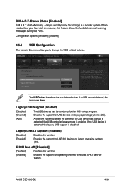
... presence of your hard disk errors occur, this feature allows the hard disk to report warning messages during the POST. If no USB devices are connected. UEFI BIOS Utility - The USB Devices item shows the auto-detected values. Advanced Mode Exit Main Back Ai Tweaker Advanced Advanced\ USB Configuration > Monitor USB Configuration USB Devices: 1 Keyboard, 1 Mouse, 4 Hubs Legacy USB Support Enabled Legacy USB3.0 Support Enabled EHCI Hand-off feature. Legacy USB3.0 Support [Enabled] [Disabled] Disables the function. [Enabled] Enables the support for operating systems without...
... presence of your hard disk errors occur, this feature allows the hard disk to report warning messages during the POST. If no USB devices are connected. UEFI BIOS Utility - The USB Devices item shows the auto-detected values. Advanced Mode Exit Main Back Ai Tweaker Advanced Advanced\ USB Configuration > Monitor USB Configuration USB Devices: 1 Keyboard, 1 Mouse, 4 Hubs Legacy USB Support Enabled Legacy USB3.0 Support Enabled EHCI Hand-off feature. Legacy USB3.0 Support [Enabled] [Disabled] Disables the function. [Enabled] Enables the support for operating systems without...
User Guide
Page 125
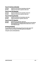
Use and keys to get the system ready for ErP requirement. When set to generate a wake event. Power On By RTC [Disabled] [Disabled] [Enabled] Disables RTC from generating a wake event. [Enabled] Enables the Ring device to Enabled, all other PME options will become user-configurable with set to generate a wake event. ErP Ready [Disabled] This item allows user to switch off . When set values. Power On By Ring [Disabled] [Disabled] Disables the Ring device from generating a wake event. Configuration options: [Disabled] [Enabled] ASUS ESC1000 G2 4-43...
Use and keys to get the system ready for ErP requirement. When set to generate a wake event. Power On By RTC [Disabled] [Disabled] [Enabled] Disables RTC from generating a wake event. [Enabled] Enables the Ring device to Enabled, all other PME options will become user-configurable with set to generate a wake event. ErP Ready [Disabled] This item allows user to switch off . When set values. Power On By Ring [Disabled] [Disabled] Disables the Ring device from generating a wake event. Configuration options: [Disabled] [Enabled] ASUS ESC1000 G2 4-43...
User Guide
Page 135
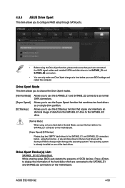
... hard drives as normal SATA connectors. Mode change at a time before using only one of SATA devices. ASUS ESC1000 G2 4-53 Drive Xpert Device(s) List: SATA6G _E1/ E2 (Navy Blue) While entering setup, BIOS auto detects the presence of the hard drives. Press to display the information of data from the SATA6G_E1 drive to the SATA6G_E2 drive. [Normal Mode] When using this function, or else all data stored in Normal Mode, connect the hard disk to the SATA6G_E1 connector on the motherboard. [Super Speed...
... hard drives as normal SATA connectors. Mode change at a time before using only one of SATA devices. ASUS ESC1000 G2 4-53 Drive Xpert Device(s) List: SATA6G _E1/ E2 (Navy Blue) While entering setup, BIOS auto detects the presence of the hard drives. Press to display the information of data from the SATA6G_E1 drive to the SATA6G_E2 drive. [Normal Mode] When using this function, or else all data stored in Normal Mode, connect the hard disk to the SATA6G_E1 connector on the motherboard. [Super Speed...

User Guide
Page 142
... boot device: SATA: XXXXXXXXXXXXXXXX USB XXXXXXXXXXXXXXXXX UEFI: XXXXXXXXXXXXXXXX Enter Setup ↑ and ↓ to move selection ENTER to select boot device ESC to show the BIOS Boot Device Select Menu. Turn off the computer and disconnect all SATA hard disk drives (optional). 4.10.4 ASUS BIOS Updater The ASUS BIOS Updater allows you can use as a backup when the BIOS fails or gets corrupted during the updating process. The succeeding utility screens are for reference only. Prepare the motherboard support DVD and a USB flash drive...
... boot device: SATA: XXXXXXXXXXXXXXXX USB XXXXXXXXXXXXXXXXX UEFI: XXXXXXXXXXXXXXXX Enter Setup ↑ and ↓ to move selection ENTER to select boot device ESC to show the BIOS Boot Device Select Menu. Turn off the computer and disconnect all SATA hard disk drives (optional). 4.10.4 ASUS BIOS Updater The ASUS BIOS Updater allows you can use as a backup when the BIOS fails or gets corrupted during the updating process. The succeeding utility screens are for reference only. Prepare the motherboard support DVD and a USB flash drive...
User Guide
Page 146
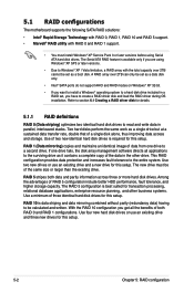
...install Windows® XP Service Pack 3 or later versions before using Serial ATA hard disk drives. This RAID configuration provides data protection and increases fault tolerance to the surviving drive as a boot disk. Among the advantages of both data and parity information across three or more hard disk drives. Use two new drives or use an existing drive and three new drives for this setup. 5-2 Chapter 5: RAID configuration 5.1 RAID configurations The motherboard supports the following SATA RAID solutions: • Intel® Rapid Storage Technology with RAID 0, RAID 1, RAID...
...install Windows® XP Service Pack 3 or later versions before using Serial ATA hard disk drives. This RAID configuration provides data protection and increases fault tolerance to the surviving drive as a boot disk. Among the advantages of both data and parity information across three or more hard disk drives. Use two new drives or use an existing drive and three new drives for this setup. 5-2 Chapter 5: RAID configuration 5.1 RAID configurations The motherboard supports the following SATA RAID solutions: • Intel® Rapid Storage Technology with RAID 0, RAID 1, RAID...
User Guide
Page 147
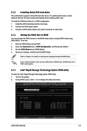
...Menu ASUS ESC1000 G2 5-3 Enter the BIOS Setup during POST. 2. Reset Disks to [RAID Mode]. 4. 5.1.2 Installing Serial ATA hard disks The motherboard supports Serial ATA hard disk drives. For optimal performance, install identical drives of SATA ports to Chapter 4 for a RAID configuration: 1. To install the SATA hard disks for details on entering and navigating through the BIOS Setup. To do this: 1. Save your changes, and then exit the BIOS Setup. Refer to RAID mode, all SATA ports run at RAID mode together. 5.1.4 Intel® Rapid Storage Technology Option ROM utility...
...Menu ASUS ESC1000 G2 5-3 Enter the BIOS Setup during POST. 2. Reset Disks to [RAID Mode]. 4. 5.1.2 Installing Serial ATA hard disks The motherboard supports Serial ATA hard disk drives. For optimal performance, install identical drives of SATA ports to Chapter 4 for a RAID configuration: 1. To install the SATA hard disks for details on entering and navigating through the BIOS Setup. To do this: 1. Save your changes, and then exit the BIOS Setup. Refer to RAID mode, all SATA ports run at RAID mode together. 5.1.4 Intel® Rapid Storage Technology Option ROM utility...
User Guide
Page 157
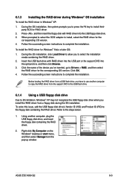
... RAID driver into the USB port or the support DVD into the USB floppy disk drive. 3. When prompted to select the SCSI adapter to install thirdparty SCSI or RAID driver. 2. ASUS ESC1000 G2 6-3 Before loading the RAID driver from a USB flash drive, you have to OS limitation, Windows® XP may not recognize the USB floppy disk drive when you 've inserted, go to the steps below: 1. Using another computer to copy the RAID driver from the support DVD to the USB flash drive. 6.1.4 Using a USB floppy disk drive...
... RAID driver into the USB port or the support DVD into the USB floppy disk drive. 3. When prompted to select the SCSI adapter to install thirdparty SCSI or RAID driver. 2. ASUS ESC1000 G2 6-3 Before loading the RAID driver from a USB flash drive, you have to OS limitation, Windows® XP may not recognize the USB floppy disk drive when you 've inserted, go to the steps below: 1. Using another computer to copy the RAID driver from the support DVD to the USB flash drive. 6.1.4 Using a USB floppy disk drive...

User Guide
Page 160
... contains the drivers, software applications, and utilities that the motherboard supports. Click an item to install The Make Disk menu contains items to run the DVD. 6-6 Chapter 6: Driver installation Visit the ASUS website(www.asus.com) for updates. 6.2.1 Running the support DVD Place the support DVD into the optical drive. The DVD automatically displays the Drivers menu if Autorun is NOT enabled in your computer, browse the contents of the user manual. Click an icon to locate the file...
... contains the drivers, software applications, and utilities that the motherboard supports. Click an item to install The Make Disk menu contains items to run the DVD. 6-6 Chapter 6: Driver installation Visit the ASUS website(www.asus.com) for updates. 6.2.1 Running the support DVD Place the support DVD into the optical drive. The DVD automatically displays the Drivers menu if Autorun is NOT enabled in your computer, browse the contents of the user manual. Click an icon to locate the file...

User Guide
Page 194
... Quadro graphics card and Tesla computing processor card(s). 3. Connect either one 8-pin power connector or two 6-pin power connectors from the menu. SLI bridge Goldfingers 4. To verify graphics card driver installation, right-click My Computer and select Properties from the power supply to install the device drivers. 5. Click the "+" sign before Display adapters, and the installed graphics card and computing processor card(s) should appear. Click the Hardware tab, and then click Device Manager. 2. Connect a display cable to the graphics card.
... Quadro graphics card and Tesla computing processor card(s). 3. Connect either one 8-pin power connector or two 6-pin power connectors from the menu. SLI bridge Goldfingers 4. To verify graphics card driver installation, right-click My Computer and select Properties from the power supply to install the device drivers. 5. Click the "+" sign before Display adapters, and the installed graphics card and computing processor card(s) should appear. Click the Hardware tab, and then click Device Manager. 2. Connect a display cable to the graphics card.


