C8HM70-I User's Manual
Page 1
Motherboard C8HM70-I SERIES • C8HM70-I • C8HM70-I/HDMI
Motherboard C8HM70-I SERIES • C8HM70-I • C8HM70-I/HDMI
C8HM70-I User's Manual
Page 8
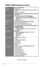
...Realtek® 887VD 8-channel High Definition Audio CODEC • Use a chassis with Max. ASUS CrashFree BIOS 3 - Ai Suite II 1 x PS/2 keyboard/mouse combo port 1 x VGA port 1 x HDMI port (C8HM70-I /O connectors Intel® Celeron® 847 (BGA1023) Intel® HM70 chipset 2 x...8226; Refer to support an 8-channel audio output. Intel® HD Graphics support - C8HM70-I SERIES specifications summary CPU Chipset Memory Graphics Expansion slots Storage LAN Audio USB ASUS unique features Back Panel I/O ports Internal I /HDMI only) 1 x LAN (RJ-45) port 4 x USB 2.0/1.1 ports 2 x USB...
...Realtek® 887VD 8-channel High Definition Audio CODEC • Use a chassis with Max. ASUS CrashFree BIOS 3 - Ai Suite II 1 x PS/2 keyboard/mouse combo port 1 x VGA port 1 x HDMI port (C8HM70-I /O connectors Intel® Celeron® 847 (BGA1023) Intel® HM70 chipset 2 x...8226; Refer to support an 8-channel audio output. Intel® HD Graphics support - C8HM70-I SERIES specifications summary CPU Chipset Memory Graphics Expansion slots Storage LAN Audio USB ASUS unique features Back Panel I/O ports Internal I /HDMI only) 1 x LAN (RJ-45) port 4 x USB 2.0/1.1 ports 2 x USB...
C8HM70-I User's Manual
Page 10
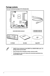
... module) VGA Super I/O LAN_USB34 RTL 8111F AUDIO AAFP ALC 887 Intel® HM70 64Mb BIOS SATA6G_1 SATA3G_1 EATXPWR Lithium Cell CMOS Power USB1112 CLRTC F_PANEL C8HM70-I/HDMI SPEAKER CHASSIS PCIEX16_1 SB_PWR ASUS C8HM70-I/HDMI motherboard User Manual 1 x Serial ATA 3.0 Gb/s cable 1 x Serial ATA 6.0 Gb/s cable 1 x I/O-Shield User Guide Support DVD •...
... module) VGA Super I/O LAN_USB34 RTL 8111F AUDIO AAFP ALC 887 Intel® HM70 64Mb BIOS SATA6G_1 SATA3G_1 EATXPWR Lithium Cell CMOS Power USB1112 CLRTC F_PANEL C8HM70-I/HDMI SPEAKER CHASSIS PCIEX16_1 SB_PWR ASUS C8HM70-I/HDMI motherboard User Manual 1 x Serial ATA 3.0 Gb/s cable 1 x Serial ATA 6.0 Gb/s cable 1 x I/O-Shield User Guide Support DVD •...
C8HM70-I User's Manual
Page 11
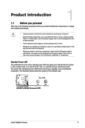
..., to avoid damaging them due to static electricity. • Hold components by the edges to the motherboard, peripherals, or components. SB_PWR C8HM70-I/HDMI ON OFF Standby Power Powered Off C8HM70-I/HDMI Onboard LED ASUS C8HM70-I Series 1-1 Product introduction 1 1.1 Before you proceed Take note of the onboard LED. This is detached from the wall socket before removing...
..., to avoid damaging them due to static electricity. • Hold components by the edges to the motherboard, peripherals, or components. SB_PWR C8HM70-I/HDMI ON OFF Standby Power Powered Off C8HM70-I/HDMI Onboard LED ASUS C8HM70-I Series 1-1 Product introduction 1 1.1 Before you proceed Take note of the onboard LED. This is detached from the wall socket before removing...
C8HM70-I User's Manual
Page 12
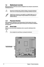
... part of your chassis to ensure that you physical injury and damage motherboard components. Place this user guide are for C8HM70-I /HDMI models. The package contents vary from models. Do not overtighten the screws! Doing so can cause you unplug the ...power cord before installing or removing the motherboard. Failure to the chassis. 1.2 Motherboard overview Before you place it . C8HM70-I Series motherboards include C8HM70-I and C8HM70-I /HDMI only. 1.2.1 Placement direction When installing the motherboard, ensure that you install the motherboard, study the configuration of the ...
... part of your chassis to ensure that you physical injury and damage motherboard components. Place this user guide are for C8HM70-I /HDMI models. The package contents vary from models. Do not overtighten the screws! Doing so can cause you unplug the ...power cord before installing or removing the motherboard. Failure to the chassis. 1.2 Motherboard overview Before you place it . C8HM70-I Series motherboards include C8HM70-I and C8HM70-I /HDMI only. 1.2.1 Placement direction When installing the motherboard, ensure that you install the motherboard, study the configuration of the ...
C8HM70-I User's Manual
Page 13
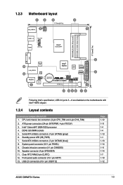
...sockets 5. USB 2.0 connectors (10-1 pin USB1112) Page 1-12 1-11 1-4 1-4 1-13 1-1 1-13 1-14 1-11 1-14 1-7 1-10 1-12 ASUS C8HM70-I /HDMI PCIEX16_1 F_PANEL SPEAKER CHASSIS SB_PWR 11 10 9 8 7 6 Following Intel's specification, USB 2.0 ports 5 ~ 8 are disabled on the motherboards with ...SPEAKER) 11. Serial ATA 6.0Gb/s connectors (7-pin SATA6G [gray]) 6. 1.2.3 Motherboard layout 1 2 3 4 17.0cm(6.7in) KB_USB910 ATX12V USB3_12 CHA_FAN HDMI CPU_FAN Intel® Celeron847 DDR3 DIMM_B1 (64bit, 204-pin module) DDR3 DIMM_A1 (64bit, 204-pin module) 17.0cm(6.7in) VGA 5 Super I/O 13 ...
...sockets 5. USB 2.0 connectors (10-1 pin USB1112) Page 1-12 1-11 1-4 1-4 1-13 1-1 1-13 1-14 1-11 1-14 1-7 1-10 1-12 ASUS C8HM70-I /HDMI PCIEX16_1 F_PANEL SPEAKER CHASSIS SB_PWR 11 10 9 8 7 6 Following Intel's specification, USB 2.0 ports 5 ~ 8 are disabled on the motherboards with ...SPEAKER) 11. Serial ATA 6.0Gb/s connectors (7-pin SATA6G [gray]) 6. 1.2.3 Motherboard layout 1 2 3 4 17.0cm(6.7in) KB_USB910 ATX12V USB3_12 CHA_FAN HDMI CPU_FAN Intel® Celeron847 DDR3 DIMM_B1 (64bit, 204-pin module) DDR3 DIMM_A1 (64bit, 204-pin module) 17.0cm(6.7in) VGA 5 Super I/O 13 ...
C8HM70-I User's Manual
Page 14
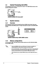
...8226; This motherboard does not support DIMMs made up of the DDR3 DIMM sockets: DIMM_B1 DIMM_A1 Channel Channel A Channel B Sockets DIMM_A1 DIMM_B1 C8HM70-I/HDMI C8HM70-I /HDMI CPU Celeron847 1.4 System memory 1.4.1 Overview This motherboard comes with two Double Data Rate 3 (DDR3) Small Outline Dual Inline Memory Modules (...more memory on the motherboard, the actual usable memory for the OS can be about 3GB or less. Intel® Celeron847 C8HM70-I/HDMI C8HM70-I /HDMI 204-pin DDR3 DIMM sockets 1.4.2 Memory configurations You may install 512MB, 1GB, 2GB, 4GB and 8GB unbuffered non‑...
...8226; This motherboard does not support DIMMs made up of the DDR3 DIMM sockets: DIMM_B1 DIMM_A1 Channel Channel A Channel B Sockets DIMM_A1 DIMM_B1 C8HM70-I/HDMI C8HM70-I /HDMI CPU Celeron847 1.4 System memory 1.4.1 Overview This motherboard comes with two Double Data Rate 3 (DDR3) Small Outline Dual Inline Memory Modules (...more memory on the motherboard, the actual usable memory for the OS can be about 3GB or less. Intel® Celeron847 C8HM70-I/HDMI C8HM70-I /HDMI 204-pin DDR3 DIMM sockets 1.4.2 Memory configurations You may install 512MB, 1GB, 2GB, 4GB and 8GB unbuffered non‑...

C8HM70-I User's Manual
Page 17
...clearing the CMOS, reinstall the battery. • You do not help, remove the onboard battery and move the cap back to pins 1-2. 3. ASUS C8HM70-I /HDMI Clear RTC RAM To erase the RTC RAM: 1. You can clear the CMOS memory of date, time, and system setup parameters by erasing the ...CMOS RTC RAM data. CLRTC 12 23 C8HM70-I/HDMI Normal (Default) Clear RTC C8HM70-I Series 1-7 The onboard button cell battery powers the RAM data in CMOS. Keep the cap on CLRTC jumper default position. Removing the ...
...clearing the CMOS, reinstall the battery. • You do not help, remove the onboard battery and move the cap back to pins 1-2. 3. ASUS C8HM70-I /HDMI Clear RTC RAM To erase the RTC RAM: 1. You can clear the CMOS memory of date, time, and system setup parameters by erasing the ...CMOS RTC RAM data. CLRTC 12 23 C8HM70-I/HDMI Normal (Default) Clear RTC C8HM70-I Series 1-7 The onboard button cell battery powers the RAM data in CMOS. Keep the cap on CLRTC jumper default position. Removing the ...
C8HM70-I User's Manual
Page 19
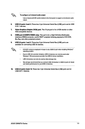
...Serial Bus (USB) ports are for USB 2.0/1.1 devices. 7. Video Graphics Adapter (VGA) port. USB 3.0 ports 1 and 2. USB 2.0 ports 9 and 10. ASUS C8HM70-I /HDMI only). These two 9-pin Universal Serial Bus (USB) ports are available for connecting USB 3.0 devices. • DO NOT connect a keyboard / mouse to any ... used as data storage only. • We strongly recommend that you connect USB 3.0 devices to support an 8-channel audio output. 6. HDMI port (C8HM70-I Series 1-9 To configure an 8-channel audio output: Use a chassis with HD audio module in the front panel to USB 3.0 ports...
...Serial Bus (USB) ports are for USB 2.0/1.1 devices. 7. Video Graphics Adapter (VGA) port. USB 3.0 ports 1 and 2. USB 2.0 ports 9 and 10. ASUS C8HM70-I /HDMI only). These two 9-pin Universal Serial Bus (USB) ports are available for connecting USB 3.0 devices. • DO NOT connect a keyboard / mouse to any ... used as data storage only. • We strongly recommend that you connect USB 3.0 devices to support an 8-channel audio output. 6. HDMI port (C8HM70-I Series 1-9 To configure an 8-channel audio output: Use a chassis with HD audio module in the front panel to USB 3.0 ports...

C8HM70-I User's Manual
Page 20
... I/O module that you connect a high-definition front panel audio module to this connector to avail of the front panel audio I /HDMI Front panel audio connector • We recommend that supports either HD Audio or legacy AC`97 audio standard. By default, this connector...NC AAFP PIN 1 PIN 1 MIC2 MICPWR Line out_R NC Line out_L PORT1 L PORT1 R PORT2 R SENSE_SEND PORT2 L C8HM70-I/HDMI HD-audio-compliant Legacy AC'97 pin definition compliant definition C8HM70-I /O module cable to this connector, set the item to [HD]. 1.7.2 Internal connectors 1. Front panel audio connector (10...
... I/O module that you connect a high-definition front panel audio module to this connector to avail of the front panel audio I /HDMI Front panel audio connector • We recommend that supports either HD Audio or legacy AC`97 audio standard. By default, this connector...NC AAFP PIN 1 PIN 1 MIC2 MICPWR Line out_R NC Line out_L PORT1 L PORT1 R PORT2 R SENSE_SEND PORT2 L C8HM70-I/HDMI HD-audio-compliant Legacy AC'97 pin definition compliant definition C8HM70-I /O module cable to this connector, set the item to [HD]. 1.7.2 Internal connectors 1. Front panel audio connector (10...
C8HM70-I User's Manual
Page 21
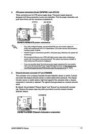
...1 GND +5 Volts +5 Volts +5 Volts -5 Volts GND GND GND PSON# GND -12 Volts +3 Volts C8HM70-I Series 1-11 CHASSIS +5VSB_MB Chassis Signal GND C8HM70-I/HDMI C8HM70-I/HDMI Chassis intrusion connector ASUS C8HM70-I /HDMI ATX power connectors • For a fully configured system, we recommend that you use a power supply unit (... a chassis component is inadequate. • If you intend to the Recommended Power Supply Wattage Calculator at http://support.asus. Chassis intrusion connector (4-1 pin CHASSIS) This connector is then generated as a chassis intrusion event. The signal is ...
...1 GND +5 Volts +5 Volts +5 Volts -5 Volts GND GND GND PSON# GND -12 Volts +3 Volts C8HM70-I Series 1-11 CHASSIS +5VSB_MB Chassis Signal GND C8HM70-I/HDMI C8HM70-I/HDMI Chassis intrusion connector ASUS C8HM70-I /HDMI ATX power connectors • For a fully configured system, we recommend that you use a power supply unit (... a chassis component is inadequate. • If you intend to the Recommended Power Supply Wattage Calculator at http://support.asus. Chassis intrusion connector (4-1 pin CHASSIS) This connector is then generated as a chassis intrusion event. The signal is ...
C8HM70-I User's Manual
Page 22
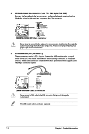
These are for USB 2.0 ports. USB+5V USB_P11USB_P11+ GND NC PIN 1 USB+5V USB_P12USB_P12+ GND USB1112 C8HM70-I/HDMI C8HM70-I /HDMI CPU fan connector Do not forget to connect the fan cables to the fan connectors on the fan connectors! 5. 4. ...The USB module cable is purchased separately. 1-12 Chapter 1: Product introduction CHA_FAN GND CHA FAN PWR CHA FAN IN CHA FAN PWM C8HM70-I/HDMI CPU_FAN GND +12V Rotation C8HM70-I /HDMI USB2.0 connector Never connect a 1394 cable to 480 Mbps connection speed. CPU and chassis fan connectors (3-pin CPU_FAN, 4-pin CHA_FAN...
These are for USB 2.0 ports. USB+5V USB_P11USB_P11+ GND NC PIN 1 USB+5V USB_P12USB_P12+ GND USB1112 C8HM70-I/HDMI C8HM70-I /HDMI CPU fan connector Do not forget to connect the fan cables to the fan connectors on the fan connectors! 5. 4. ...The USB module cable is purchased separately. 1-12 Chapter 1: Product introduction CHA_FAN GND CHA FAN PWR CHA FAN IN CHA FAN PWM C8HM70-I/HDMI CPU_FAN GND +12V Rotation C8HM70-I /HDMI USB2.0 connector Never connect a 1394 cable to 480 Mbps connection speed. CPU and chassis fan connectors (3-pin CPU_FAN, 4-pin CHA_FAN...

C8HM70-I User's Manual
Page 23
... connects to [AHCI]. Serial ATA 6.0Gb/s connectors (7-pin SATA6G [gray]) This connector connects to [AHCI]. GND RSATA_RXP1 RSATA_RXN1 RSATA_TXN1 RSATA_TXP1 GND GND 6. SATA3G_1 C8HM70-I/HDMI C8HM70-I /HDMI SATA 6.0Gb/s connector • You must install Windows® XP Service Pack 3 or later version before using Serial ATA hard disk drives. • When...the BIOS to Serial ATA 6.0 Gb/s hard disk drives via Serial ATA 3.0 Gb/s signal cables. GND RSATA_TXP1 RSATA_TXN1 GND RSATA_RXN1 RSATA_RXP1 GND ASUS C8HM70-I Series 1-13 See section 2.5.3 SATA Configuration for details. 7.
... connects to [AHCI]. Serial ATA 6.0Gb/s connectors (7-pin SATA6G [gray]) This connector connects to [AHCI]. GND RSATA_RXP1 RSATA_RXN1 RSATA_TXN1 RSATA_TXP1 GND GND 6. SATA3G_1 C8HM70-I/HDMI C8HM70-I /HDMI SATA 6.0Gb/s connector • You must install Windows® XP Service Pack 3 or later version before using Serial ATA hard disk drives. • When...the BIOS to Serial ATA 6.0 Gb/s hard disk drives via Serial ATA 3.0 Gb/s signal cables. GND RSATA_TXP1 RSATA_TXN1 GND RSATA_RXN1 RSATA_RXP1 GND ASUS C8HM70-I Series 1-13 See section 2.5.3 SATA Configuration for details. 7.
C8HM70-I User's Manual
Page 24
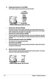
...LED. The HD LED lights up when you to this connector. SPEAKER +5V GND GND Speaker Out CC88HM H7M0-I/7H0DM-II PIN 1 C8HM70-I /HDMI System panel connector • System power LED (2-pin PWRLED) This 2-pin connector is for system reboot without turning off button (2-pin PWRBTN... The system power LED lights up or flashes when data is read from or written to this connector. Ground HWRST# (NC) C8HM70-I/HDMI +HD_LED RESET C8HM70-I /HDMI Speaker Out Connector 1-14 Chapter 1: Product introduction Connect the HDD Activity LED cable to the HDD. • ATX power button/...
...LED. The HD LED lights up when you to this connector. SPEAKER +5V GND GND Speaker Out CC88HM H7M0-I/7H0DM-II PIN 1 C8HM70-I /HDMI System panel connector • System power LED (2-pin PWRLED) This 2-pin connector is for system reboot without turning off button (2-pin PWRBTN... The system power LED lights up or flashes when data is read from or written to this connector. Ground HWRST# (NC) C8HM70-I/HDMI +HD_LED RESET C8HM70-I /HDMI Speaker Out Connector 1-14 Chapter 1: Product introduction Connect the HDD Activity LED cable to the HDD. • ATX power button/...
C8HM70-I User's Manual
Page 29
...when it fails or gets corrupted during the updating process. ASUS C8HM70-I /HDMI model. • The BIOS file in the removable device to C8HM70I.CAP for the C8HM70-I model and HM70IH.CAP for the BIOS file. 2.1.3 ASUS CrashFree BIOS 3 utility The ASUS CrashFree BIOS 3 is an auto recovery tool that allows ...you to load default BIOS values. Download the latest BIOS file from the ASUS website at www.asus.com. The utility automatically checks the devices for the C8HM70-I Series 2-3 You can cause system boot failure! Insert the support DVD to the optical drive or...
...when it fails or gets corrupted during the updating process. ASUS C8HM70-I /HDMI model. • The BIOS file in the removable device to C8HM70I.CAP for the C8HM70-I model and HM70IH.CAP for the BIOS file. 2.1.3 ASUS CrashFree BIOS 3 utility The ASUS CrashFree BIOS 3 is an auto recovery tool that allows ...you to load default BIOS values. Download the latest BIOS file from the ASUS website at www.asus.com. The utility automatically checks the devices for the C8HM70-I Series 2-3 You can cause system boot failure! Insert the support DVD to the optical drive or...
C8HM70-I User's Manual
Page 31
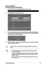
... confirm BIOS update. 4. Press to switch between screen fields and use the keys to exit BIOS Updater. Refer to ensure system compatibility and stability. ASUS C8HM70-I .CAP 8390656 2012-02-09 17:30:48 Note [Enter] Select or Load [Up/Down/Home/End] Move [Tab] Switch [B] Backup [V]...load the BIOS default settings to section 2.9 Exit menu for DOS V1.30 Current ROM BOARD: C8HM70-I/HDMI VER: 0202 DATE: 08/29/2012 Update ROM BOARD: Unknown VER: Unknown DATE: Unknown PATH: A:\ A: C8HM70-I Series 2-5 Updating the BIOS file To update the BIOS file using BIOS Updater: 1. BIOS...
... confirm BIOS update. 4. Press to switch between screen fields and use the keys to exit BIOS Updater. Refer to ensure system compatibility and stability. ASUS C8HM70-I .CAP 8390656 2012-02-09 17:30:48 Note [Enter] Select or Load [Up/Down/Home/End] Move [Tab] Switch [B] Backup [V]...load the BIOS default settings to section 2.9 Exit menu for DOS V1.30 Current ROM BOARD: C8HM70-I/HDMI VER: 0202 DATE: 08/29/2012 Update ROM BOARD: Unknown VER: Unknown DATE: Unknown PATH: A:\ A: C8HM70-I Series 2-5 Updating the BIOS file To update the BIOS file using BIOS Updater: 1. BIOS...

