C8HM70-I User's Manual
Page 10
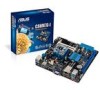
... module) VGA Super I/O LAN_USB34 RTL 8111F AUDIO AAFP ALC 887 Intel® HM70 64Mb BIOS SATA6G_1 SATA3G_1 EATXPWR Lithium Cell CMOS Power USB1112 CLRTC F_PANEL C8HM70-I/HDMI SPEAKER CHASSIS PCIEX16_1 SB_PWR ASUS C8HM70-I/HDMI motherboard User Manual 1 x Serial ATA 3.0 Gb/s cable 1 x Serial ATA 6.0 Gb/s cable 1 x I/O-Shield User Guide Support DVD •...
... module) VGA Super I/O LAN_USB34 RTL 8111F AUDIO AAFP ALC 887 Intel® HM70 64Mb BIOS SATA6G_1 SATA3G_1 EATXPWR Lithium Cell CMOS Power USB1112 CLRTC F_PANEL C8HM70-I/HDMI SPEAKER CHASSIS PCIEX16_1 SB_PWR ASUS C8HM70-I/HDMI motherboard User Manual 1 x Serial ATA 3.0 Gb/s cable 1 x Serial ATA 6.0 Gb/s cable 1 x I/O-Shield User Guide Support DVD •...
C8HM70-I User's Manual
Page 11
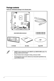
... plugging in the bag that came with a standby power LED that lights up to the motherboard, peripherals, or components. SB_PWR C8HM70-I/HDMI ON OFF Standby Power Powered Off C8HM70-I/HDMI Onboard LED ASUS C8HM70-I Series 1-1 Standby Power LED The motherboard comes with the component. • Before you install motherboard components or change any motherboard...
... plugging in the bag that came with a standby power LED that lights up to the motherboard, peripherals, or components. SB_PWR C8HM70-I/HDMI ON OFF Standby Power Powered Off C8HM70-I/HDMI Onboard LED ASUS C8HM70-I Series 1-1 Standby Power LED The motherboard comes with the component. • Before you install motherboard components or change any motherboard...
C8HM70-I User's Manual
Page 13
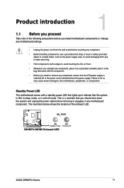
... SATA6G_1 LAN_USB34 12 RTL 8111F SATA3G_1 2 USB1112 EATXPWR AUDIO AAFP ALC 887 Lithium Cell CMOS Power CLRTC C8HM70-I Series 1-3 USB 2.0 connectors (10-1 pin USB1112) Page 1-12 1-11 1-4 1-4 1-13 1-1 1-13 1-14 1-11 1-14 1-7 1-10 1-12 ASUS C8HM70-I /HDMI PCIEX16_1 F_PANEL SPEAKER CHASSIS SB_PWR 11 10 9 8 7 6 Following Intel's specification, USB 2.0 ports 5 ~ 8 are disabled on the...
... SATA6G_1 LAN_USB34 12 RTL 8111F SATA3G_1 2 USB1112 EATXPWR AUDIO AAFP ALC 887 Lithium Cell CMOS Power CLRTC C8HM70-I Series 1-3 USB 2.0 connectors (10-1 pin USB1112) Page 1-12 1-11 1-4 1-4 1-13 1-1 1-13 1-14 1-11 1-14 1-7 1-10 1-12 ASUS C8HM70-I /HDMI PCIEX16_1 F_PANEL SPEAKER CHASSIS SB_PWR 11 10 9 8 7 6 Following Intel's specification, USB 2.0 ports 5 ~ 8 are disabled on the...

C8HM70-I User's Manual
Page 15
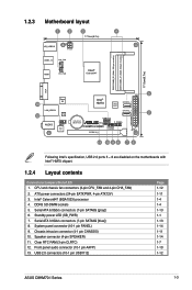
...DS 1GB DS 1GB DS 2GB DS 1GB DS 2GB DS 1GB DS 1GB DS 1GB DS 2GB DS Chip Brand Chip No. C8HM70-I Series 1-5 Timing Hynix Apacer Apacer CORSAIR CORSAIR G.SKILL G.SKILL GEIL GEIL GEIL Hynix Kingmax Kingmax Kingmax KTC ELPIDA KTC SAMSUNG ...DJ-F D1288JPNDPLD9U K4B1G0846E K4B1G0846F N2CB1616AP-BE IDSH1G-04A1F1C-10F K4B1G16460-HCF8 H5TQ1G83BFRG7C 7 7 7-7-7-20 7-7-7-20 7-7-7-20 7-7-7-20 7-7-7-20 7 7 - Visit the ASUS website at www.asus.com for the latest QVL. ASUS C8HM70-I Series Motherboard Qualified Vendors Lists (QVL) DDR3-1333 MHz capability Vendors Part No.
...DS 1GB DS 1GB DS 2GB DS 1GB DS 2GB DS 1GB DS 1GB DS 1GB DS 2GB DS Chip Brand Chip No. C8HM70-I Series 1-5 Timing Hynix Apacer Apacer CORSAIR CORSAIR G.SKILL G.SKILL GEIL GEIL GEIL Hynix Kingmax Kingmax Kingmax KTC ELPIDA KTC SAMSUNG ...DJ-F D1288JPNDPLD9U K4B1G0846E K4B1G0846F N2CB1616AP-BE IDSH1G-04A1F1C-10F K4B1G16460-HCF8 H5TQ1G83BFRG7C 7 7 7-7-7-20 7-7-7-20 7-7-7-20 7-7-7-20 7-7-7-20 7 7 - Visit the ASUS website at www.asus.com for the latest QVL. ASUS C8HM70-I Series Motherboard Qualified Vendors Lists (QVL) DDR3-1333 MHz capability Vendors Part No.

C8HM70-I User's Manual
Page 17
... due to clear the Real Time Clock (RTC) RAM in CMOS, which include system setup information such as system passwords. CLRTC 12 23 C8HM70-I/HDMI Normal (Default) Clear RTC C8HM70-I Series 1-7 Plug the power cord and turn ON the computer. 4. After clearing the CMOS, reinstall the battery. • You do not help... RAM data. Turn OFF the computer and unplug the power cord. 2. Move the jumper cap from pins 1-2 (default) to clear the CMOS RTC RAM data. ASUS C8HM70-I /HDMI Clear RTC RAM To erase the RTC RAM: 1.
... due to clear the Real Time Clock (RTC) RAM in CMOS, which include system setup information such as system passwords. CLRTC 12 23 C8HM70-I/HDMI Normal (Default) Clear RTC C8HM70-I Series 1-7 Plug the power cord and turn ON the computer. 4. After clearing the CMOS, reinstall the battery. • You do not help... RAM data. Turn OFF the computer and unplug the power cord. 2. Move the jumper cap from pins 1-2 (default) to clear the CMOS RTC RAM data. ASUS C8HM70-I /HDMI Clear RTC RAM To erase the RTC RAM: 1.
C8HM70-I User's Manual
Page 19
USB 2.0 ports 3 and 4. HDMI port (C8HM70-I Series 1-9 USB 2.0 ports 9 and 10. These two 4-pin Universal Serial Bus (USB) ports are available for connecting USB 3.0 devices. • DO NOT connect a keyboard / mouse ... a VGA monitor or other protected content. 9. This 15-pin port is HDCP compliant allowing playback of HD DVD, Blu-Ray, and other VGA-compatible devices 8. ASUS C8HM70-I /HDMI only). These two 9-pin Universal Serial Bus (USB) ports are for USB 2.0/1.1 devices. 7. These two 4-pin Universal Serial Bus (USB) ports are for USB...
USB 2.0 ports 3 and 4. HDMI port (C8HM70-I Series 1-9 USB 2.0 ports 9 and 10. These two 4-pin Universal Serial Bus (USB) ports are available for connecting USB 3.0 devices. • DO NOT connect a keyboard / mouse ... a VGA monitor or other protected content. 9. This 15-pin port is HDCP compliant allowing playback of HD DVD, Blu-Ray, and other VGA-compatible devices 8. ASUS C8HM70-I /HDMI only). These two 9-pin Universal Serial Bus (USB) ports are for USB 2.0/1.1 devices. 7. These two 4-pin Universal Serial Bus (USB) ports are for USB...
C8HM70-I User's Manual
Page 21
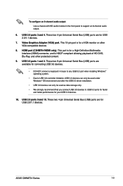
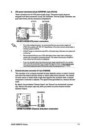
... signal is inadequate. • If you intend to the Recommended Power Supply Wattage Calculator at http://support.asus. CHASSIS +5VSB_MB Chassis Signal GND C8HM70-I/HDMI C8HM70-I/HDMI Chassis intrusion connector ASUS C8HM70-I /HDMI ATX power connectors • For a fully configured system, we recommend that you use a ... to fit these connectors in only one end of 350 W. • DO NOT forget to this connector. ATX12V EATXPWR +12V DC +12V DC C8HM70-I/HDMI GND GND +3 Volts +12 Volts +12 Volts +5V Standby Power OK PIN 1 GND +5 Volts GND +5 Volts GND +3 Volts +3 ...
... signal is inadequate. • If you intend to the Recommended Power Supply Wattage Calculator at http://support.asus. CHASSIS +5VSB_MB Chassis Signal GND C8HM70-I/HDMI C8HM70-I/HDMI Chassis intrusion connector ASUS C8HM70-I /HDMI ATX power connectors • For a fully configured system, we recommend that you use a ... to fit these connectors in only one end of 350 W. • DO NOT forget to this connector. ATX12V EATXPWR +12V DC +12V DC C8HM70-I/HDMI GND GND +3 Volts +12 Volts +12 Volts +5V Standby Power OK PIN 1 GND +5 Volts GND +5 Volts GND +3 Volts +3 ...

C8HM70-I User's Manual
Page 23
... drives via Serial ATA 3.0 Gb/s signal cables. See section 2.5.3 SATA Configuration for details. 7. GND RSATA_TXP1 RSATA_TXN1 GND RSATA_RXN1 RSATA_RXP1 GND ASUS C8HM70-I /HDMI SATA 3.0Gb/s connector • You must install Windows® XP Service Pack 3 or later version before using Serial ATA ... the BIOS to Serial ATA 3.0 Gb/s hard disk drive or optical drive via Serial ATA 6.0 Gb/s signal cables. SATA3G_1 C8HM70-I/HDMI C8HM70-I Series 1-13 See section 2.5.3 SATA Configuration for details. GND RSATA_RXP1 RSATA_RXN1 RSATA_TXN1 RSATA_TXP1 GND GND 6. Serial ATA 3.0Gb/s connectors...
... drives via Serial ATA 3.0 Gb/s signal cables. See section 2.5.3 SATA Configuration for details. 7. GND RSATA_TXP1 RSATA_TXN1 GND RSATA_RXN1 RSATA_RXP1 GND ASUS C8HM70-I /HDMI SATA 3.0Gb/s connector • You must install Windows® XP Service Pack 3 or later version before using Serial ATA ... the BIOS to Serial ATA 3.0 Gb/s hard disk drive or optical drive via Serial ATA 6.0 Gb/s signal cables. SATA3G_1 C8HM70-I/HDMI C8HM70-I Series 1-13 See section 2.5.3 SATA Configuration for details. GND RSATA_RXP1 RSATA_RXN1 RSATA_TXN1 RSATA_TXP1 GND GND 6. Serial ATA 3.0Gb/s connectors...
C8HM70-I User's Manual
Page 25
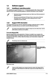
... at any time without notice. Double-click the ASSETUP.EXE to avail all motherboard features. ASUS C8HM70-I Series 1-15 The contents of the Support DVD to display their respective menus. Click Drivers, Utilities, Make Disk, Manual, and Contact tabs ... the Specials screen which contains the unique features of your hardware. • Motherboard settings and hardware options vary. Refer to maximize the features of ASUS motherboard. The following screen is enabled in your OS documentation for detailed information. • Ensure that you install Windows® XP Service Pack 3...
... at any time without notice. Double-click the ASSETUP.EXE to avail all motherboard features. ASUS C8HM70-I Series 1-15 The contents of the Support DVD to display their respective menus. Click Drivers, Utilities, Make Disk, Manual, and Contact tabs ... the Specials screen which contains the unique features of your hardware. • Motherboard settings and hardware options vary. Refer to maximize the features of ASUS motherboard. The following screen is enabled in your OS documentation for detailed information. • Ensure that you install Windows® XP Service Pack 3...
C8HM70-I User's Manual
Page 27
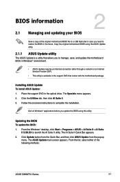
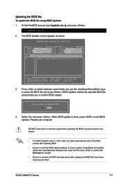
... appears. 2. Follow the onscreen instructions to launch the AI Suite II utility. Click Update button from the Quick Bar, and then click ASUS Update from the popup menu. BIOS information 2.1 Managing and updating your BIOS 2 Save a copy of the original motherboard BIOS file to ...case you to manage, save, and update the motherboard BIOS in Windows® environment. • ASUS Update requires an Internet connection either of the following methods: ASUS C8HM70-I Series 2-1 The ASUS Update main screen appears. Place the support DVD in the optical drive. Updating the BIOS To update...
... appears. 2. Follow the onscreen instructions to launch the AI Suite II utility. Click Update button from the Quick Bar, and then click ASUS Update from the popup menu. BIOS information 2.1 Managing and updating your BIOS 2 Save a copy of the original motherboard BIOS file to ...case you to manage, save, and update the motherboard BIOS in Windows® environment. • ASUS Update requires an Internet connection either of the following methods: ASUS C8HM70-I Series 2-1 The ASUS Update main screen appears. Place the support DVD in the optical drive. Updating the BIOS To update...
C8HM70-I User's Manual
Page 29
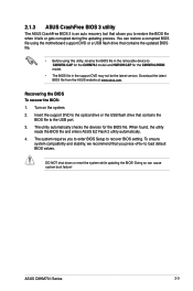
... contains the BIOS file to recover BIOS setting. The utility automatically checks the devices for the C8HM70-I Series 2-3 Recovering the BIOS To recover the BIOS: 1. To ensure system compatibility and stability...be the latest version. Download the latest BIOS file from the ASUS website at www.asus.com. You can cause system boot failure! ASUS C8HM70-I /HDMI model. • The BIOS file in the removable... device to C8HM70I.CAP for the C8HM70-I model and HM70IH.CAP for the BIOS...
... contains the BIOS file to recover BIOS setting. The utility automatically checks the devices for the C8HM70-I Series 2-3 Recovering the BIOS To recover the BIOS: 1. To ensure system compatibility and stability...be the latest version. Download the latest BIOS file from the ASUS website at www.asus.com. You can cause system boot failure! ASUS C8HM70-I /HDMI model. • The BIOS file in the removable... device to C8HM70I.CAP for the C8HM70-I model and HM70IH.CAP for the BIOS...
C8HM70-I User's Manual
Page 31
... VER: 0202 DATE: 08/29/2012 Update ROM BOARD: Unknown VER: Unknown DATE: Unknown PATH: A:\ A: C8HM70-I Series 2-5 BIOS Updater checks the selected BIOS file and prompts you have disconnected them. ASUS C8HM70-I .CAP 8390656 2012-02-09 17:30:48 Note [Enter] Select or Load [Up/Down/Home/End] Move [Tab] Switch [B] Backup...
... VER: 0202 DATE: 08/29/2012 Update ROM BOARD: Unknown VER: Unknown DATE: Unknown PATH: A:\ A: C8HM70-I Series 2-5 BIOS Updater checks the selected BIOS file and prompts you have disconnected them. ASUS C8HM70-I .CAP 8390656 2012-02-09 17:30:48 Note [Enter] Select or Load [Up/Down/Home/End] Move [Tab] Switch [B] Backup...
C8HM70-I User's Manual
Page 33
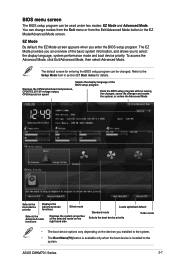
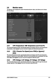
... Exit/Advanced Mode button in section 2.7 Boot menu for entering the BIOS setup program can be used under two modes: EZ Mode and Advanced Mode. ASUS C8HM70-I Series 2-7 Refer to the Setup Mode item in the EZ Mode/Advanced Mode screen. Displays the CPU/motherboard temperature, CPU/5V/3.3V/12V voltage output...
... Exit/Advanced Mode button in section 2.7 Boot menu for entering the BIOS setup program can be used under two modes: EZ Mode and Advanced Mode. ASUS C8HM70-I Series 2-7 Refer to the Setup Mode item in the EZ Mode/Advanced Mode screen. Displays the CPU/motherboard temperature, CPU/5V/3.3V/12V voltage output...
C8HM70-I User's Manual
Page 35
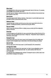
... keys At the bottom right corner of the field opposite the item. Press the Up/Down arrow keys or / keys to the previous menu screen. ASUS C8HM70-I Series 2-9 Configuration fields These fields show the values for that do not fit on the screen. Press or use the USB mouse to click this...
... keys At the bottom right corner of the field opposite the item. Press the Up/Down arrow keys or / keys to the previous menu screen. ASUS C8HM70-I Series 2-9 Configuration fields These fields show the values for that do not fit on the screen. Press or use the USB mouse to click this...

C8HM70-I User's Manual
Page 37
... you might be able to see or change only selected fields in changing an administrator password, but press when prompted to create/confirm the password. ASUS C8HM70-I Series 2-11 To set a user password: 1. From the Enter Current Password box, key in a password, then press . 3. From the Create New Password box, key in...
... you might be able to see or change only selected fields in changing an administrator password, but press when prompted to create/confirm the password. ASUS C8HM70-I Series 2-11 To set a user password: 1. From the Enter Current Password box, key in a password, then press . 3. From the Create New Password box, key in...
C8HM70-I User's Manual
Page 39
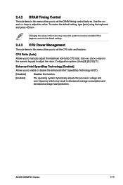
ASUS C8HM70-I Series 2-13 CPU Ratio [Auto] Allows you to adjust the value. If this happens, revert to the default settings. 2.4.3 CPU Power Management The sub-items ...
ASUS C8HM70-I Series 2-13 CPU Ratio [Auto] Allows you to adjust the value. If this happens, revert to the default settings. 2.4.3 CPU Power Management The sub-items ...
C8HM70-I User's Manual
Page 41
... C1E [Auto] Allows you to boot even without support for CPUs with extended CPUID functions. [Disabled] Disables this function. [Enabled] Enables the C1E support function. ASUS C8HM70-I Series 2-15 This item should be enabled in order to enable or disable the CPU C1E. [Auto] Set this item automatically. [Disabled] Disables this function...
... C1E [Auto] Allows you to boot even without support for CPUs with extended CPUID functions. [Disabled] Disables this function. [Enabled] Enables the C1E support function. ASUS C8HM70-I Series 2-15 This item should be enabled in order to enable or disable the CPU C1E. [Auto] Set this item automatically. [Disabled] Disables this function...
C8HM70-I User's Manual
Page 43
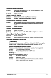
... add-on random workloads by the iGPU. Configuration options: [Disabled] [Enabled] iGPU Multi-Monitor [Disabled] Allows you to [AHCI] or [IDE]. Configuration options: [Disabled] [Enabled] ASUS C8HM70-I Series 2-17 Status Check [Enabled] This item only appears when you set the SATA Mode Selection item to [AHCI] and allows you to internally optimize...
... add-on random workloads by the iGPU. Configuration options: [Disabled] [Enabled] iGPU Multi-Monitor [Disabled] Allows you to [AHCI] or [IDE]. Configuration options: [Disabled] [Enabled] ASUS C8HM70-I Series 2-17 Status Check [Enabled] This item only appears when you set the SATA Mode Selection item to [AHCI] and allows you to internally optimize...

C8HM70-I User's Manual
Page 45
...] and allows you to legacy AC'97 Realtek LAN Controller [Enabled] [Enabled] Enables the Realtek LAN controller. [Disabled] Disables the controller. Configuration options: [Enabled] [Disabled] ASUS C8HM70-I Series 2-19 Realtek PXE OPROM [Disabled] This item appears only when you set the front panel audio connector (AAFP) mode to legacy AC'97 or...
...] and allows you to legacy AC'97 Realtek LAN Controller [Enabled] [Enabled] Enables the Realtek LAN controller. [Disabled] Disables the controller. Configuration options: [Enabled] [Disabled] ASUS C8HM70-I Series 2-19 Realtek PXE OPROM [Disabled] This item appears only when you set the front panel audio connector (AAFP) mode to legacy AC'97 or...
C8HM70-I User's Manual
Page 47
... the detected speed. 2.6.3 CPU Voltage, 3.3V Voltage, 5V Voltage, 12V Voltage The onboard hardware monitor automatically detects the voltage output through the onboard voltage regulators. ASUS C8HM70-I Series 2-21 Select Ignore if you do not want to display the detected temperatures. 2.6.2 CPU / Chassis Fan Speed [xxxx RPM] or [Ignore] / [N/A] The onboard hardware...
... the detected speed. 2.6.3 CPU Voltage, 3.3V Voltage, 5V Voltage, 12V Voltage The onboard hardware monitor automatically detects the voltage output through the onboard voltage regulators. ASUS C8HM70-I Series 2-21 Select Ignore if you do not want to display the detected temperatures. 2.6.2 CPU / Chassis Fan Speed [xxxx RPM] or [Ignore] / [N/A] The onboard hardware...


