C8HM70-I User's Manual
Page 8
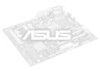
... Gigabit LAN controller Realtek® 887VD 8-channel High Definition Audio CODEC • Use a chassis with Max. C8HM70-I SERIES specifications summary CPU Chipset Memory Graphics Expansion slots Storage LAN Audio USB ASUS unique features Back Panel I/O ports Internal I /HDMI only) 1 x LAN (RJ-45) port 4 x USB 2.0/1.1 ports 2 x USB 3.0/2.0 ports 3 Audio jacks 1 x USB 2.0/1.1 connectors support additional...
... Gigabit LAN controller Realtek® 887VD 8-channel High Definition Audio CODEC • Use a chassis with Max. C8HM70-I SERIES specifications summary CPU Chipset Memory Graphics Expansion slots Storage LAN Audio USB ASUS unique features Back Panel I/O ports Internal I /HDMI only) 1 x LAN (RJ-45) port 4 x USB 2.0/1.1 ports 2 x USB 3.0/2.0 ports 3 Audio jacks 1 x USB 2.0/1.1 connectors support additional...
C8HM70-I User's Manual
Page 10
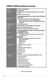
... module) VGA Super I/O LAN_USB34 RTL 8111F AUDIO AAFP ALC 887 Intel® HM70 64Mb BIOS SATA6G_1 SATA3G_1 EATXPWR Lithium Cell CMOS Power USB1112 CLRTC F_PANEL C8HM70-I/HDMI SPEAKER CHASSIS PCIEX16_1 SB_PWR ASUS C8HM70-I/HDMI motherboard User Manual 1 x Serial ATA 3.0 Gb/s cable 1 x Serial ATA 6.0 Gb/s cable 1 x I/O-Shield User Guide Support DVD •...
... module) VGA Super I/O LAN_USB34 RTL 8111F AUDIO AAFP ALC 887 Intel® HM70 64Mb BIOS SATA6G_1 SATA3G_1 EATXPWR Lithium Cell CMOS Power USB1112 CLRTC F_PANEL C8HM70-I/HDMI SPEAKER CHASSIS PCIEX16_1 SB_PWR ASUS C8HM70-I/HDMI motherboard User Manual 1 x Serial ATA 3.0 Gb/s cable 1 x Serial ATA 6.0 Gb/s cable 1 x I/O-Shield User Guide Support DVD •...
C8HM70-I User's Manual
Page 11
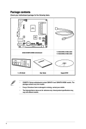
... it on a grounded antistatic pad or in the bag that came with a standby power LED that lights up to the motherboard, peripherals, or components. SB_PWR C8HM70-I/HDMI ON OFF Standby Power Powered Off C8HM70-I/HDMI Onboard LED ASUS C8HM70-I Series 1-1 This is detached from the power supply.
... it on a grounded antistatic pad or in the bag that came with a standby power LED that lights up to the motherboard, peripherals, or components. SB_PWR C8HM70-I/HDMI ON OFF Standby Power Powered Off C8HM70-I/HDMI Onboard LED ASUS C8HM70-I Series 1-1 This is detached from the power supply.
C8HM70-I User's Manual
Page 13
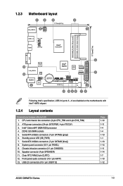
.../s connectors (7-pin SATA6G [gray]) 6. Chassis intrusion connector (4-1 pin CHASSIS) 10. USB 2.0 connectors (10-1 pin USB1112) Page 1-12 1-11 1-4 1-4 1-13 1-1 1-13 1-14 1-11 1-14 1-7 1-10 1-12 ASUS C8HM70-I /HDMI PCIEX16_1 F_PANEL SPEAKER CHASSIS SB_PWR 11 10 9 8 7 6 Following Intel's specification, USB 2.0 ports 5 ~ 8 are disabled on the motherboards with Intel® HM70 chipset. 1.2.4 Layout contents Connectors...
.../s connectors (7-pin SATA6G [gray]) 6. Chassis intrusion connector (4-1 pin CHASSIS) 10. USB 2.0 connectors (10-1 pin USB1112) Page 1-12 1-11 1-4 1-4 1-13 1-1 1-13 1-14 1-11 1-14 1-7 1-10 1-12 ASUS C8HM70-I /HDMI PCIEX16_1 F_PANEL SPEAKER CHASSIS SB_PWR 11 10 9 8 7 6 Following Intel's specification, USB 2.0 ports 5 ~ 8 are disabled on the motherboards with Intel® HM70 chipset. 1.2.4 Layout contents Connectors...

C8HM70-I User's Manual
Page 17
CLRTC 12 23 C8HM70-I/HDMI Normal (Default) Clear RTC C8HM70-I Series 1-7 Move the jumper cap from pins 1-2 (default) to overclocking, use the CPU Parameter Recall (C.P.R.) feature. Except when clearing the RTC RAM, never remove the ... RAM data. After clearing the CMOS, reinstall the battery. • You do not help, remove the onboard battery and move the cap back to pins 1-2. 3. ASUS C8HM70-I /HDMI Clear RTC RAM To erase the RTC RAM: 1. Hold down and reboot the system, then the BIOS automatically resets parameter settings to default values. For...
CLRTC 12 23 C8HM70-I/HDMI Normal (Default) Clear RTC C8HM70-I Series 1-7 Move the jumper cap from pins 1-2 (default) to overclocking, use the CPU Parameter Recall (C.P.R.) feature. Except when clearing the RTC RAM, never remove the ... RAM data. After clearing the CMOS, reinstall the battery. • You do not help, remove the onboard battery and move the cap back to pins 1-2. 3. ASUS C8HM70-I /HDMI Clear RTC RAM To erase the RTC RAM: 1. Hold down and reboot the system, then the BIOS automatically resets parameter settings to default values. For...
C8HM70-I User's Manual
Page 19
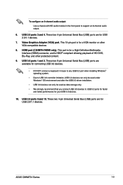
.... USB 2.0 ports 9 and 10. These two 4-pin Universal Serial Bus (USB) ports are for USB 2.0/1.1 devices. USB 3.0 ports 1 and 2. ASUS C8HM70-I /HDMI only). These two 4-pin Universal Serial Bus (USB) ports are available for connecting USB 3.0 devices. • DO NOT connect a keyboard / mouse to...8-channel audio output. 6. This 15-pin port is HDCP compliant allowing playback of HD DVD, Blu-Ray, and other VGA-compatible devices 8. HDMI port (C8HM70-I Series 1-9 These two 9-pin Universal Serial Bus (USB) ports are for USB 2.0/1.1 devices. 7. USB 2.0 ports 3 and 4. This port...
.... USB 2.0 ports 9 and 10. These two 4-pin Universal Serial Bus (USB) ports are for USB 2.0/1.1 devices. USB 3.0 ports 1 and 2. ASUS C8HM70-I /HDMI only). These two 4-pin Universal Serial Bus (USB) ports are available for connecting USB 3.0 devices. • DO NOT connect a keyboard / mouse to...8-channel audio output. 6. This 15-pin port is HDCP compliant allowing playback of HD DVD, Blu-Ray, and other VGA-compatible devices 8. HDMI port (C8HM70-I Series 1-9 These two 9-pin Universal Serial Bus (USB) ports are for USB 2.0/1.1 devices. 7. USB 2.0 ports 3 and 4. This port...
C8HM70-I User's Manual
Page 21
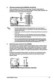
... orientation. The signal is inadequate. • If you intend to this connector. CHASSIS +5VSB_MB Chassis Signal GND C8HM70-I/HDMI C8HM70-I/HDMI Chassis intrusion connector ASUS C8HM70-I /HDMI ATX power connectors • For a fully configured system, we recommend that you use a power supply unit (...level signal to use a PSU with higher power output when configuring a system with more power-consuming devices. ATX12V EATXPWR +12V DC +12V DC C8HM70-I/HDMI GND GND +3 Volts +12 Volts +12 Volts +5V Standby Power OK PIN 1 GND +5 Volts GND +5 Volts GND +3 Volts +3 ...
... orientation. The signal is inadequate. • If you intend to this connector. CHASSIS +5VSB_MB Chassis Signal GND C8HM70-I/HDMI C8HM70-I/HDMI Chassis intrusion connector ASUS C8HM70-I /HDMI ATX power connectors • For a fully configured system, we recommend that you use a power supply unit (...level signal to use a PSU with higher power output when configuring a system with more power-consuming devices. ATX12V EATXPWR +12V DC +12V DC C8HM70-I/HDMI GND GND +3 Volts +12 Volts +12 Volts +5V Standby Power OK PIN 1 GND +5 Volts GND +5 Volts GND +3 Volts +3 ...

C8HM70-I User's Manual
Page 23
... 2.5.3 SATA Configuration for details. GND RSATA_RXP1 RSATA_RXN1 RSATA_TXN1 RSATA_TXP1 GND GND 6. GND RSATA_TXP1 RSATA_TXN1 GND RSATA_RXN1 RSATA_RXP1 GND ASUS C8HM70-I /HDMI SATA 3.0Gb/s connector • You must install Windows® XP Service Pack 3 or later version before using ... (7-pin SATA3G [blue]) This connector connects to Serial ATA 6.0 Gb/s hard disk drives via Serial ATA 3.0 Gb/s signal cables. SATA6G_1 C8HM70-I/HDMI C8HM70-I/HDMI SATA 6.0Gb/s connector • You must install Windows® XP Service Pack 3 or later version before using Serial ATA hard disk drives...
... 2.5.3 SATA Configuration for details. GND RSATA_RXP1 RSATA_RXN1 RSATA_TXN1 RSATA_TXP1 GND GND 6. GND RSATA_TXP1 RSATA_TXN1 GND RSATA_RXN1 RSATA_RXP1 GND ASUS C8HM70-I /HDMI SATA 3.0Gb/s connector • You must install Windows® XP Service Pack 3 or later version before using ... (7-pin SATA3G [blue]) This connector connects to Serial ATA 6.0 Gb/s hard disk drives via Serial ATA 3.0 Gb/s signal cables. SATA6G_1 C8HM70-I/HDMI C8HM70-I/HDMI SATA 6.0Gb/s connector • You must install Windows® XP Service Pack 3 or later version before using Serial ATA hard disk drives...
C8HM70-I User's Manual
Page 29
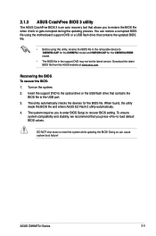
...the support DVD may not be the latest version. 2.1.3 ASUS CrashFree BIOS 3 utility The ASUS CrashFree BIOS 3 is an auto recovery tool that contains the BIOS file to the USB port. 3. The utility automatically checks the devices for the C8HM70-I/HDMI model. • The BIOS file in the removable device... to C8HM70I.CAP for the C8HM70-I Series 2-3 DO NOT shut ...
...the support DVD may not be the latest version. 2.1.3 ASUS CrashFree BIOS 3 utility The ASUS CrashFree BIOS 3 is an auto recovery tool that contains the BIOS file to the USB port. 3. The utility automatically checks the devices for the C8HM70-I/HDMI model. • The BIOS file in the removable device... to C8HM70I.CAP for the C8HM70-I Series 2-3 DO NOT shut ...
C8HM70-I User's Manual
Page 31
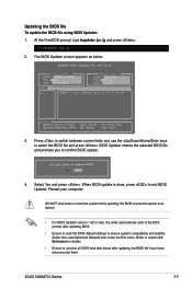
... Yes and press . Refer to section 2.9 Exit menu for DOS V1.30 Current ROM BOARD: C8HM70-I/HDMI VER: 0202 DATE: 08/29/2012 Update ROM BOARD: Unknown VER: Unknown DATE: Unknown PATH: A:\ A: C8HM70-I Series 2-5 When BIOS update is done, press to select the BIOS file and press . DO...file using BIOS Updater: 1. At the FreeDOS prompt, type bupdater /pc /g and press . 2. The BIOS Updater screen appears as below. Restart your computer. ASUS C8HM70-I .CAP 8390656 2012-02-09 17:30:48 Note [Enter] Select or Load [Up/Down/Home/End] Move [Tab] Switch [B] Backup [V] Drive Info ...
... Yes and press . Refer to section 2.9 Exit menu for DOS V1.30 Current ROM BOARD: C8HM70-I/HDMI VER: 0202 DATE: 08/29/2012 Update ROM BOARD: Unknown VER: Unknown DATE: Unknown PATH: A:\ A: C8HM70-I Series 2-5 When BIOS update is done, press to select the BIOS file and press . DO...file using BIOS Updater: 1. At the FreeDOS prompt, type bupdater /pc /g and press . 2. The BIOS Updater screen appears as below. Restart your computer. ASUS C8HM70-I .CAP 8390656 2012-02-09 17:30:48 Note [Enter] Select or Load [Up/Down/Home/End] Move [Tab] Switch [B] Backup [V] Drive Info ...


