
User Guide
Page 2
... to the source code of such software and/or other Free Open Source Software Licenses. to duly provide complete source code as source code archives, etc. E9606 First Edition August 2014 Copyright © 2014 ASUSTeK COMPUTER INC. No part of this manual, including the products and software described in it shipped to, by ASUS; Product warranty or service will be registered...
... to the source code of such software and/or other Free Open Source Software Licenses. to duly provide complete source code as source code archives, etc. E9606 First Edition August 2014 Copyright © 2014 ASUSTeK COMPUTER INC. No part of this manual, including the products and software described in it shipped to, by ASUS; Product warranty or service will be registered...
User Guide
Page 4
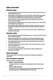
... the power supply is set to change system settings through the BIOS Setup menus. Do not place the product in your dealer immediately. • To avoid short circuits, keep paper clips, screws, and staples away from connectors, slots, sockets and circuitry. • Avoid dust, humidity, and temperature extremes. If you are using, contact your retailer. Operation safety • Before installing the motherboard and adding devices on...
... the power supply is set to change system settings through the BIOS Setup menus. Do not place the product in your dealer immediately. • To avoid short circuits, keep paper clips, screws, and staples away from connectors, slots, sockets and circuitry. • Avoid dust, humidity, and temperature extremes. If you are using, contact your retailer. Operation safety • Before installing the motherboard and adding devices on...
User Guide
Page 6
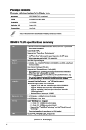
... items. Motherboard ASUS B85M-V PLUS motherboard Cables 2 x Serial ATA 6.0 Gb/s cables Accessories 1 x I/O Shield Application DVD Support DVD Documentation User Guide If any of the above items is subject to the physical characteristics of DDR3 1600MHz. Intel® HD Graphics support Multi-VGA output support: DVI-D, RGB port - Supports DVI-D with max. Integrated Graphics Processor - Supports Intel® InTruTM 3D/Quick Sync Video/Clear Video HD Technology/InsiderTM - Supports Intel® Rapid Start Technology* and Intel® Smart Connect Technology* * These...
... items. Motherboard ASUS B85M-V PLUS motherboard Cables 2 x Serial ATA 6.0 Gb/s cables Accessories 1 x I/O Shield Application DVD Support DVD Documentation User Guide If any of the above items is subject to the physical characteristics of DDR3 1600MHz. Intel® HD Graphics support Multi-VGA output support: DVI-D, RGB port - Supports DVI-D with max. Integrated Graphics Processor - Supports Intel® InTruTM 3D/Quick Sync Video/Clear Video HD Technology/InsiderTM - Supports Intel® Rapid Start Technology* and Intel® Smart Connect Technology* * These...

User Guide
Page 8
...x LAN (RJ-45) port 3 x Audio jacks support 8-channel audio output 2 x USB 2.0/1.1 connectors support additional 4 USB 2.0/1.1 ports 1 x USB 3.0/2.0 connectors support additional 2 USB 3.0/2.0 ports 4 x SATA 6.0Gb/s connectors 2 x SATA 3.0Gb/s connectors 1 x COM header 1 x TPM header 1 x CPU fan connector 1 x Chassis fan connector 1 x Front panel audio connector 1 x S/PDIF Out connector 1 x 24-pin EATX power connector 1 x 4-pin EATX 12V power connector 1 x Speaker connector 1 x System panel connector 1 x CLRTC jumper (2-pin) 64 Mb Flash ROM, UEFI AMI BIOS, PnP, DMI2.0, WfM2.0, SM BIOS 2.7, ACPI...
...x LAN (RJ-45) port 3 x Audio jacks support 8-channel audio output 2 x USB 2.0/1.1 connectors support additional 4 USB 2.0/1.1 ports 1 x USB 3.0/2.0 connectors support additional 2 USB 3.0/2.0 ports 4 x SATA 6.0Gb/s connectors 2 x SATA 3.0Gb/s connectors 1 x COM header 1 x TPM header 1 x CPU fan connector 1 x Chassis fan connector 1 x Front panel audio connector 1 x S/PDIF Out connector 1 x 24-pin EATX power connector 1 x 4-pin EATX 12V power connector 1 x Speaker connector 1 x System panel connector 1 x CLRTC jumper (2-pin) 64 Mb Flash ROM, UEFI AMI BIOS, PnP, DMI2.0, WfM2.0, SM BIOS 2.7, ACPI...

User Guide
Page 9
... change any motherboard settings. • Unplug the power cord from the power supply. The edge with external ports goes to the rear part of the chassis as the power supply case, to avoid damaging them due to static electricity. • Hold components by circles to secure the motherboard to the motherboard, peripherals, or components. 1.2 Motherboard overview Before you install or remove any component, ensure that the ATX power supply is switched...
... change any motherboard settings. • Unplug the power cord from the power supply. The edge with external ports goes to the rear part of the chassis as the power supply case, to avoid damaging them due to static electricity. • Hold components by circles to secure the motherboard to the motherboard, peripherals, or components. 1.2 Motherboard overview Before you install or remove any component, ensure that the ATX power supply is switched...

User Guide
Page 11
.... Front panel audio connector (10-1 pin AAFP) 15. B85M-V PLUS B85M-V PLUS CPU socket LGA1150 Unplug all power cables before installing the CPU. • Upon purchase of repair only if the damage is on the LGA1150 socket. • The product warranty does not cover damage to the PnP cap/socket contacts/motherboard components. Speaker connector (4-pin SPEAKER) 7. ASUS B85M-V PLUS 1-3 CPU and chassis fan connectors (4-pin CPU_FAN, 4-pin CHA_FAN) 3. Intel® B85 Serial ATA 3.0Gb/s connector (7-pin SATA3G_1~2 [black]) 10. 1.2.4 Layout contents Connectors/Jumpers/Slots/LED 1. USB...
.... Front panel audio connector (10-1 pin AAFP) 15. B85M-V PLUS B85M-V PLUS CPU socket LGA1150 Unplug all power cables before installing the CPU. • Upon purchase of repair only if the damage is on the LGA1150 socket. • The product warranty does not cover damage to the PnP cap/socket contacts/motherboard components. Speaker connector (4-pin SPEAKER) 7. ASUS B85M-V PLUS 1-3 CPU and chassis fan connectors (4-pin CPU_FAN, 4-pin CHA_FAN) 3. Intel® B85 Serial ATA 3.0Gb/s connector (7-pin SATA3G_1~2 [black]) 10. 1.2.4 Layout contents Connectors/Jumpers/Slots/LED 1. USB...

User Guide
Page 15
... stability, use of memory, we recommend that you install 4GB or more on the motherboard. • This motherboard does not support DIMMs made up of 512 megabits (Mb) chips or less. • Memory modules with the same CAS latency. The system maps the total size of the lower-sized channel for overclocking may install varying memory sizes in the market. • The default memory operation frequency is dependent...
... stability, use of memory, we recommend that you install 4GB or more on the motherboard. • This motherboard does not support DIMMs made up of 512 megabits (Mb) chips or less. • Memory modules with the same CAS latency. The system maps the total size of the lower-sized channel for overclocking may install varying memory sizes in the market. • The default memory operation frequency is dependent...
User Guide
Page 17
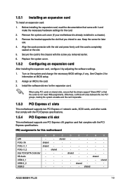
... slot and press firmly until the card is already installed in a chassis). 3. When using PCI cards on the system and change the necessary BIOS settings, if any. D shared - E - shared - Remove the bracket opposite the slot that the cards do not need IRQ assignments. Install the software drivers for this motherboard LAN PCIE x16 PCIE x1_1 PCIE x1_2 Intel PCH SATA Controller HD Audio USB2.0_1 USB2.0_2 USB3.0 A shared shared - B shared - C shared - H - Align the card connector...
... slot and press firmly until the card is already installed in a chassis). 3. When using PCI cards on the system and change the necessary BIOS settings, if any. D shared - E - shared - Remove the bracket opposite the slot that the cards do not need IRQ assignments. Install the software drivers for this motherboard LAN PCIE x16 PCIE x1_1 PCIE x1_2 Intel PCH SATA Controller HD Audio USB2.0_1 USB2.0_2 USB3.0 A shared shared - B shared - C shared - H - Align the card connector...
User Guide
Page 19
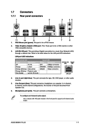
...Area Network (LAN) through a network hub. ASUS B85M-V PLUS 1-11 1.7 Connectors 1.7.1 Rear panel connectors 1 2 3 45 11 10 9 8 7 6 1. This port allows Gigabit connection to support an 8-channel audio output. In 4-channel, 6-channel, and 8-channel configurations, the function of this port becomes Front Speaker Out. 6. This port connects a microphone. Video Graphics Adapter (VGA) port. Line In port (light blue). Line Out port (lime). LAN (RJ-45) port. This port connects the tape, CD, DVD player, or other VGA-compatible devices. 3. This 15-pin port is for a VGA monitor or...
...Area Network (LAN) through a network hub. ASUS B85M-V PLUS 1-11 1.7 Connectors 1.7.1 Rear panel connectors 1 2 3 45 11 10 9 8 7 6 1. This port allows Gigabit connection to support an 8-channel audio output. In 4-channel, 6-channel, and 8-channel configurations, the function of this port becomes Front Speaker Out. 6. This port connects a microphone. Video Graphics Adapter (VGA) port. Line In port (light blue). Line Out port (lime). LAN (RJ-45) port. This port connects the tape, CD, DVD player, or other VGA-compatible devices. 3. This 15-pin port is for a VGA monitor or...
User Guide
Page 21
...]. ASUS B85M-V PLUS 1-13 AGND NC SENSE1_RETUR SENSE2_RETUR AGND NC NC NC AAFP PIN 1 PIN 1 MIC2 MICPWR Line out_R NC Line out_L PORT1 L PORT1 R PORT2 R SENSE_SEND PORT2 L B85M-V PLUS HD-audio-compliant Legacy AC'97 pin definition compliant definition B85M-V PLUS Front panel audio connector • We recommend that supports either HD Audio or legacy AC`97 audio standard. Digital audio connector (4-1 pin SPDIF_OUT) This connector is set the Front Panel Type item in the BIOS setup to...
...]. ASUS B85M-V PLUS 1-13 AGND NC SENSE1_RETUR SENSE2_RETUR AGND NC NC NC AAFP PIN 1 PIN 1 MIC2 MICPWR Line out_R NC Line out_L PORT1 L PORT1 R PORT2 R SENSE_SEND PORT2 L B85M-V PLUS HD-audio-compliant Legacy AC'97 pin definition compliant definition B85M-V PLUS Front panel audio connector • We recommend that supports either HD Audio or legacy AC`97 audio standard. Digital audio connector (4-1 pin SPDIF_OUT) This connector is set the Front Panel Type item in the BIOS setup to...

User Guide
Page 22
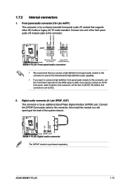
... system chassis. These are for USB 2.0 ports. USB 2.0 connectors (10-1 pin USB1112, USB910) These connectors are not jumpers! Doing so will damage the motherboard! CPU_FAN CHA_FAN B85M-V PLUS B85M-V PLUS Fan connectors Do not forget to connect the fan cables to a slot opening at the back of the connector. Only the 4-pin CPU fan supports the ASUS Fan Xpert feature. 4. Connect the USB module cable to any of maximum 1A (12 W) fan power. CPU FAN PWM CPU FAN IN CPU FAN PWR GND +5V CHA FAN IN CHA FAN...
... system chassis. These are for USB 2.0 ports. USB 2.0 connectors (10-1 pin USB1112, USB910) These connectors are not jumpers! Doing so will damage the motherboard! CPU_FAN CHA_FAN B85M-V PLUS B85M-V PLUS Fan connectors Do not forget to connect the fan cables to a slot opening at the back of the connector. Only the 4-pin CPU fan supports the ASUS Fan Xpert feature. 4. Connect the USB module cable to any of maximum 1A (12 W) fan power. CPU FAN PWM CPU FAN IN CPU FAN PWR GND +5V CHA FAN IN CHA FAN...

User Guide
Page 25
... PLUS USB3.0 Front panel connector ASUS B85M-V PLUS 1-17 Ground HWRST# (NC) PIN 1 B85M-V PLUS +HDD_LED RESET B85M-V PLUS System panel connector • System power LED (2-pin PWR_LED) This 2-pin connector is for the chassis-mounted reset button for the HDD Activity LED. The HDD LED lights up to the HDD. • ATX power button/soft-off button (2-pin PWR_BTN) This connector is for the system power button. • Reset button (2-pin RESET) This 2-pin connector is for USB-chargeable devices, optimized power efficiency and backward compatibility with USB 2.0. 9. With an installed...
... PLUS USB3.0 Front panel connector ASUS B85M-V PLUS 1-17 Ground HWRST# (NC) PIN 1 B85M-V PLUS +HDD_LED RESET B85M-V PLUS System panel connector • System power LED (2-pin PWR_LED) This 2-pin connector is for the chassis-mounted reset button for the HDD Activity LED. The HDD LED lights up to the HDD. • ATX power button/soft-off button (2-pin PWR_BTN) This connector is for the system power button. • Reset button (2-pin RESET) This 2-pin connector is for USB-chargeable devices, optimized power efficiency and backward compatibility with USB 2.0. 9. With an installed...
User Guide
Page 27
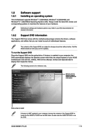
... Support DVD are subject to change at www.asus.com for detailed information. 1.8.2 Support DVD information The Support DVD that comes with the motherboard package contains the drivers, software applications, and utilities that you can install to your ASUS motherboard. ASUS B85M-V PLUS 1-19 Click Drivers, Utilities, AHCI Driver, Manual, Contact and Specials tabs to locate the file ASSETUP.EXE from the BIN folder. Motherboard settings and hardware options vary. Visit the ASUS website at any time without notice. 1.8 Software support 1.8.1 Installing...
... Support DVD are subject to change at www.asus.com for detailed information. 1.8.2 Support DVD information The Support DVD that comes with the motherboard package contains the drivers, software applications, and utilities that you can install to your ASUS motherboard. ASUS B85M-V PLUS 1-19 Click Drivers, Utilities, AHCI Driver, Manual, Contact and Specials tabs to locate the file ASSETUP.EXE from the BIN folder. Motherboard settings and hardware options vary. Visit the ASUS website at any time without notice. 1.8 Software support 1.8.1 Installing...
User Guide
Page 29
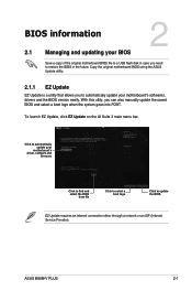
... automatically update your motherboard's softwares, drivers and the BIOS version easily. BIOS information 2.1 Managing and updating your motherboard's driver, software and firmware Model Name: B85M-V PLUS Version: 0305 Release Date: 08/08/2014 Click to find and select the BIOS from file Click to select a boot logo Click to update the BIOS EZ Update requires an Internet connection either through a network or an ISP (Internet Service Provider). Copy the original motherboard BIOS using the ASUS Update utility. 2.1.1 EZ Update EZ Update is a utility that...
... automatically update your motherboard's softwares, drivers and the BIOS version easily. BIOS information 2.1 Managing and updating your motherboard's driver, software and firmware Model Name: B85M-V PLUS Version: 0305 Release Date: 08/08/2014 Click to find and select the BIOS from file Click to select a boot logo Click to update the BIOS EZ Update requires an Internet connection either through a network or an ISP (Internet Service Provider). Copy the original motherboard BIOS using the ASUS Update utility. 2.1.1 EZ Update EZ Update is a utility that...

User Guide
Page 30
... you start using this utility, download the latest BIOS file from the ASUS website at www.asus.com. Press the Up/Down arrow keys to find the BIOS file, and then press to the USB port. 2. Reboot the system when the update process is done. • This function supports USB flash disks formatted using EZ Flash 2: 1. Press to switch to prevent system boot failure! 2-2 Chapter 2: BIOS information Select the Load Optimized Defaults item under the Exit menu...
... you start using this utility, download the latest BIOS file from the ASUS website at www.asus.com. Press the Up/Down arrow keys to find the BIOS file, and then press to the USB port. 2. Reboot the system when the update process is done. • This function supports USB flash disks formatted using EZ Flash 2: 1. Press to switch to prevent system boot failure! 2-2 Chapter 2: BIOS information Select the Load Optimized Defaults item under the Exit menu...
User Guide
Page 31
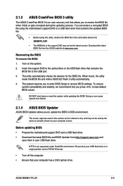
... system boot failure! 2.1.4 ASUS BIOS Updater ASUS BIOS Updater allows you to restore the BIOS file when it fails or gets corrupted during the updating process. Ensure that your computer screen. 2.1.3 ASUS CrashFree BIOS 3 utility The ASUS CrashFree BIOS 3 is an auto recovery tool that allows you to update the BIOS in DOS environment. DO NOT shut down or reset the system while updating the BIOS! Doing so can restore a corrupted BIOS file using the motherboard support DVD or a USB flash drive that...
... system boot failure! 2.1.4 ASUS BIOS Updater ASUS BIOS Updater allows you to restore the BIOS file when it fails or gets corrupted during the updating process. Ensure that your computer screen. 2.1.3 ASUS CrashFree BIOS 3 utility The ASUS CrashFree BIOS 3 is an auto recovery tool that allows you to update the BIOS in DOS environment. DO NOT shut down or reset the system while updating the BIOS! Doing so can restore a corrupted BIOS file using the motherboard support DVD or a USB flash drive that...

User Guide
Page 32
... boot device screen appears, insert the Support DVD into the optical drive then select the optical drive as the boot device. Please select boot device: E1: ASUS DVD-E818A6T (4069MB) USB DISK 2.0 (3824MB) UEFI: (FAT) USB DISK 2.0 (3824MB) Enter Setup and to move selection ENTER to select boot device ESC to FreeDOS (http://www.freedos.org)! Welcome to boot using defaults 4. On the FreeDOS prompt, type bupdater /pc /g and press . Press ENTER to boot from Drive C (optical drive) to switch...
... boot device screen appears, insert the Support DVD into the optical drive then select the optical drive as the boot device. Please select boot device: E1: ASUS DVD-E818A6T (4069MB) USB DISK 2.0 (3824MB) UEFI: (FAT) USB DISK 2.0 (3824MB) Enter Setup and to move selection ENTER to select boot device ESC to FreeDOS (http://www.freedos.org)! Welcome to boot using defaults 4. On the FreeDOS prompt, type bupdater /pc /g and press . Press ENTER to boot from Drive C (optical drive) to switch...

User Guide
Page 34
... power button to your motherboard if you do not press or , POST continues with its parameters. The BIOS screens include navigation keys and brief online help to guide you failed to the default value. Do this section are for information on your data or system. Entering BIOS Setup after POST To enter BIOS Setup after changing any BIOS setting, try to clear the CMOS and reset the motherboard to enter BIOS Setup using the BIOS Setup program. Select the Load...
... power button to your motherboard if you do not press or , POST continues with its parameters. The BIOS screens include navigation keys and brief online help to guide you failed to the default value. Do this section are for information on your data or system. Entering BIOS Setup after POST To enter BIOS Setup after changing any BIOS setting, try to clear the CMOS and reset the motherboard to enter BIOS Setup using the BIOS Setup program. Select the Load...
User Guide
Page 35
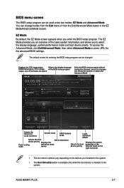
... boot device priority. BIOS menu screen The BIOS setup program can be changed. EZ Mode By default, the EZ Mode screen appears when you to the system. Displays the CPU temperature, Selects the display language DRAM information, CPU voltage of the BIOS setup program output, and CPU/chassis fan speed Exits the BIOS setup program without saving the changes, saves the changes and resets the system, or enters the Advanced Mode Selects the Advanced mode functions Normal mode ASUS Optimal mode Loads optimized default Selects the boot device priority Displays the SATA...
... boot device priority. BIOS menu screen The BIOS setup program can be changed. EZ Mode By default, the EZ Mode screen appears when you to the system. Displays the CPU temperature, Selects the display language DRAM information, CPU voltage of the BIOS setup program output, and CPU/chassis fan speed Exits the BIOS setup program without saving the changes, saves the changes and resets the system, or enters the Advanced Mode Selects the Advanced mode functions Normal mode ASUS Optimal mode Loads optimized default Selects the boot device priority Displays the SATA...

User Guide
Page 43
... can radiate radio frequency energy and, if not installed and used in accordance with manufacturer's instructions, may cause undesired operation of the monitor to the graphics card is required to radio or television reception, which the receiver is encouraged to try to correct the interference by the party responsible for a Class B digital device, pursuant to Part 15 of Industry...
... can radiate radio frequency energy and, if not installed and used in accordance with manufacturer's instructions, may cause undesired operation of the monitor to the graphics card is required to radio or television reception, which the receiver is encouraged to try to correct the interference by the party responsible for a Class B digital device, pursuant to Part 15 of Industry...


