
AT3IONT-I Series user's manual
Page 9
... panel audio connector 1 x COM connector 1 x Chassis intrusion connector 1 x SATA power connector* 1 x 24-pin EATX power connector** * For AT3IONT-I DELUXE only ** For AT3IONT-I only 8 Mb Flash ROM, AMI BIOS, PnP, DMI2.0, WfM2.0, SMBIOS 2.5, ACPI v2.0a 2 x Serial ATA cables 1 x I/O shield 1 x User Manual 1 x SATA Power ...cable* 1 x Remote Controller* 1 x Receiver* 1 x WiFi antenna* 1 x 90W DC adapter* 1 x Power cord* * For AT3IONT-I DELUXE only Drivers ASUS PC Probe II ASUS ...
... panel audio connector 1 x COM connector 1 x Chassis intrusion connector 1 x SATA power connector* 1 x 24-pin EATX power connector** * For AT3IONT-I DELUXE only ** For AT3IONT-I only 8 Mb Flash ROM, AMI BIOS, PnP, DMI2.0, WfM2.0, SMBIOS 2.5, ACPI v2.0a 2 x Serial ATA cables 1 x I/O shield 1 x User Manual 1 x SATA Power ...cable* 1 x Remote Controller* 1 x Receiver* 1 x WiFi antenna* 1 x 90W DC adapter* 1 x Power cord* * For AT3IONT-I DELUXE only Drivers ASUS PC Probe II ASUS ...

AT3IONT-I Series user's manual
Page 11
... SATA1, SATA2, SATA3, SATA4) Front panel audio connector (10-1 pin AAFP) USB connector (10-1 pin USB78, USB910) Page 1-14 1-8 1-1 1-11 1-13 1-12 ASUS AT3IONT-I DELUXE only. Chassis intrusion connector (4-1 pin CHASSIS) Page 1-13 7. 1-15 8. 1-3 9. 1-3 10. 1-12 11. 1-14 12. Doing so can damage the motherboard. 1.2.2... RCA_OUT AUDIO RTL 8112L AAFP ALC 887 USB910 USB78 NVIDIA® ION WLAN PCIEX16 SATA2 SATA4 SATA1 SATA3 SB_PWR CLRTC F_PANEL CHASSIS 6 7 8Mb BIOS 12 11 10 9 8 Place four screws into the chassis in this side towards the rear of the chassis. 1 2 3 4 17....
... SATA1, SATA2, SATA3, SATA4) Front panel audio connector (10-1 pin AAFP) USB connector (10-1 pin USB78, USB910) Page 1-14 1-8 1-1 1-11 1-13 1-12 ASUS AT3IONT-I DELUXE only. Chassis intrusion connector (4-1 pin CHASSIS) Page 1-13 7. 1-15 8. 1-3 9. 1-3 10. 1-12 11. 1-14 12. Doing so can damage the motherboard. 1.2.2... RCA_OUT AUDIO RTL 8112L AAFP ALC 887 USB910 USB78 NVIDIA® ION WLAN PCIEX16 SATA2 SATA4 SATA1 SATA3 SB_PWR CLRTC F_PANEL CHASSIS 6 7 8Mb BIOS 12 11 10 9 8 Place four screws into the chassis in this side towards the rear of the chassis. 1 2 3 4 17....
AT3IONT-I Series user's manual
Page 17
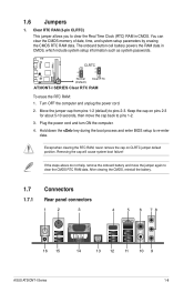
AT3IONT-I DELUXE 12 23 CLRTC Normal (Default) Clear RTC AT3IONT-I Series 1-8 Plug the power cord and turn ON the computer. 4. Hold down the key during the boot process and enter BIOS setup to pins 2-3. Removing the cap will cause system boot failure! After clearing the CMOS, reinstall the battery. ...1.7 Connectors 1.7.1 Rear panel connectors 1 2 3 4 5 6 78 16 15 14 13 12 11 10 9 ASUS AT3IONT-I SERIES Clear RTC RAM To...
AT3IONT-I DELUXE 12 23 CLRTC Normal (Default) Clear RTC AT3IONT-I Series 1-8 Plug the power cord and turn ON the computer. 4. Hold down the key during the boot process and enter BIOS setup to pins 2-3. Removing the cap will cause system boot failure! After clearing the CMOS, reinstall the battery. ...1.7 Connectors 1.7.1 Rear panel connectors 1 2 3 4 5 6 78 16 15 14 13 12 11 10 9 ASUS AT3IONT-I SERIES Clear RTC RAM To...

AT3IONT-I Series user's manual
Page 20
... GND RSATA_RXN1 RSATA_RXP1 GND RSATA_TXN1 RSATA_TXP1 GND GND RSATA_TXP3 RSATA_TXN3 GND RSATA_RXP3 RSATA_RXN3 GND AT3IONT-I DELUXE SATA2 GND RSATA_RXN2 RSATA_RXP2 GND RSATA_TXN2 RSATA_TXP2 GND SATA4 GND RSATA_TXP4 RSATA_TXN4 GND RSATA_RXP4 RSATA_RXN4 GND AT3IONT-I SERIES SATA connectors • Install the Windows® XP Service Pack 2 ...XP operating system on RAID/AHCI, refer to the RAID/AHCI Supplementary Guide included in the folder named Manual in the BIOS to other media such as a USB flash disk and load RAID driver during installing Windows® Vista OS with the Serial...
... GND RSATA_RXN1 RSATA_RXP1 GND RSATA_TXN1 RSATA_TXP1 GND GND RSATA_TXP3 RSATA_TXN3 GND RSATA_RXP3 RSATA_RXN3 GND AT3IONT-I DELUXE SATA2 GND RSATA_RXN2 RSATA_RXP2 GND RSATA_TXN2 RSATA_TXP2 GND SATA4 GND RSATA_TXP4 RSATA_TXN4 GND RSATA_RXP4 RSATA_RXN4 GND AT3IONT-I SERIES SATA connectors • Install the Windows® XP Service Pack 2 ...XP operating system on RAID/AHCI, refer to the RAID/AHCI Supplementary Guide included in the folder named Manual in the BIOS to other media such as a USB flash disk and load RAID driver during installing Windows® Vista OS with the Serial...

AT3IONT-I Series user's manual
Page 22
...AAFP PIN 1 PIN 1 MIC2 MICPWR Line out_R NC Line out_L PORT1 L PORT1 R PORT2 R SENSE_SEND PORT2 L AT3IONT-I DELUXE HD-audio-compliant Legacy AC'97 pin definition compliant definition AT3IONT-I SERIES fan connectors 5. 4. Do not forget to connect the fan cables to [HD Audio]. These are not jumpers... the fan connectors! Front panel audio connector (10-1 pin AAFP) This connector is set the Front Panel Select item in the BIOS setup to this connector is for details. 1-13 Chapter 1: Product introduction Insufficient air flow inside the system may damage the motherboard ...
...AAFP PIN 1 PIN 1 MIC2 MICPWR Line out_R NC Line out_L PORT1 L PORT1 R PORT2 R SENSE_SEND PORT2 L AT3IONT-I DELUXE HD-audio-compliant Legacy AC'97 pin definition compliant definition AT3IONT-I SERIES fan connectors 5. 4. Do not forget to connect the fan cables to [HD Audio]. These are not jumpers... the fan connectors! Front panel audio connector (10-1 pin AAFP) This connector is set the Front Panel Select item in the BIOS setup to this connector is for details. 1-13 Chapter 1: Product introduction Insufficient air flow inside the system may damage the motherboard ...


