
AT3IONT-I Series user's manual
Page 4
Contents 2.3 Main menu 2-4 2.3.1 System Time [xx:xx:xx 2-5 2.3.2 System Date [Day xx/xx/xxxx 2-5 2.3.3 SATA 1~4 2-5 2.3.4 Storage Configuration 2-6 2.3.5 System Information 2-6 2.4 Advanced menu 2-6 2.4.1 CPU Configuration 2-7 2.4.2 JumperFree Configuration 2-7 2.4.3 Chipset 2-9 2.4.4 Onboard Devices Configuration 2-9 2.4.5 USB Configuration 2-10 2.4.6 PCI PnP 2-11 2.5 Power menu 2-11 2.5.1 Suspend Mode [Auto 2-11 2.5.2 ACPI 2.0 Support [Disabled 2-11 2.5.3 ACPI APIC Support [Enabled 2-11 2.5.4 Control EuP...
Contents 2.3 Main menu 2-4 2.3.1 System Time [xx:xx:xx 2-5 2.3.2 System Date [Day xx/xx/xxxx 2-5 2.3.3 SATA 1~4 2-5 2.3.4 Storage Configuration 2-6 2.3.5 System Information 2-6 2.4 Advanced menu 2-6 2.4.1 CPU Configuration 2-7 2.4.2 JumperFree Configuration 2-7 2.4.3 Chipset 2-9 2.4.4 Onboard Devices Configuration 2-9 2.4.5 USB Configuration 2-10 2.4.6 PCI PnP 2-11 2.5 Power menu 2-11 2.5.1 Suspend Mode [Auto 2-11 2.5.2 ACPI 2.0 Support [Disabled 2-11 2.5.3 ACPI APIC Support [Enabled 2-11 2.5.4 Control EuP...

AT3IONT-I Series user's manual
Page 9
... ROM, AMI BIOS, PnP, DMI2.0, WfM2.0, SMBIOS 2.5, ACPI v2.0a 2 x Serial ATA cables 1 x I/O shield 1 x User Manual 1 x SATA Power cable* 1 x Remote Controller* 1 x Receiver* 1 x WiFi antenna* 1 x 90W DC adapter* 1 x Power cord* * For AT3IONT-I DELUXE only Drivers ASUS PC Probe II ASUS Update Anti-virus software (OEM version) Mini ITX form factor: 6.75 in x 6.75 in (17.1cm x 17...
... ROM, AMI BIOS, PnP, DMI2.0, WfM2.0, SMBIOS 2.5, ACPI v2.0a 2 x Serial ATA cables 1 x I/O shield 1 x User Manual 1 x SATA Power cable* 1 x Remote Controller* 1 x Receiver* 1 x WiFi antenna* 1 x 90W DC adapter* 1 x Power cord* * For AT3IONT-I DELUXE only Drivers ASUS PC Probe II ASUS Update Anti-virus software (OEM version) Mini ITX form factor: 6.75 in x 6.75 in (17.1cm x 17...

AT3IONT-I Series user's manual
Page 11
...-1 pin USB78, USB910) Page 1-14 1-8 1-1 1-11 1-13 1-12 ASUS AT3IONT-I DELUXE only. The layout illustrations in the correct orientation. Atom 330 processor 4. DO NOT overtighten the screws! Serial port connectors (10-1 pin COM1) 3. CPU, power, and chassis fan connectors (3-pin CPU_FAN, 3-pin PWR_FAN, 3-pin CHA_FAN) 2. SATA power connectors (4-pin SATA_PWR1) 6. PWR_FAN Atom 330 CHA_FAN SPDIF_O...
...-1 pin USB78, USB910) Page 1-14 1-8 1-1 1-11 1-13 1-12 ASUS AT3IONT-I DELUXE only. The layout illustrations in the correct orientation. Atom 330 processor 4. DO NOT overtighten the screws! Serial port connectors (10-1 pin COM1) 3. CPU, power, and chassis fan connectors (3-pin CPU_FAN, 3-pin PWR_FAN, 3-pin CHA_FAN) 2. SATA power connectors (4-pin SATA_PWR1) 6. PWR_FAN Atom 330 CHA_FAN SPDIF_O...
AT3IONT-I Series user's manual
Page 21
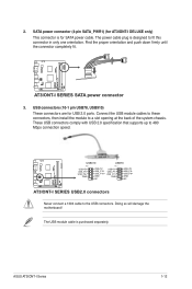
...-1 pin USB78, USB910) These connectors are for SATA power cable. AT3IONT-I DELUXE USB910 USB78 PIN 1 USB+5V USB_P9USB_P9+ GND USB+5V USB_P10USB_P10+ GND NC PIN 1 USB+5V USB_P7USB_P7+ GND USB+5V USB_P8USB_P8+ GND NC AT3IONT-I Series 1-12 The USB module cable is designed to the USB connectors. ASUS AT3IONT-I SERIES USB2.0 connectors Never connect a 1394 cable...
...-1 pin USB78, USB910) These connectors are for SATA power cable. AT3IONT-I DELUXE USB910 USB78 PIN 1 USB+5V USB_P9USB_P9+ GND USB+5V USB_P10USB_P10+ GND NC PIN 1 USB+5V USB_P7USB_P7+ GND USB+5V USB_P8USB_P8+ GND NC AT3IONT-I Series 1-12 The USB module cable is designed to the USB connectors. ASUS AT3IONT-I SERIES USB2.0 connectors Never connect a 1394 cable...
AT3IONT-I Series user's manual
Page 34
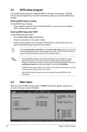
... 2.3 Main menu When you enter the BIOS Setup program, the Main menu screen appears, giving you do not press , POST continues with its parameters. SATA 1 SATA 2 SATA 3 SATA 4 [Not Detected] [Not Detected] [Not Detected] [Not Detected] Use [+] or [-] to select a field. Entering BIOS Setup at startup To enter ...BIOS Setup at www.asus.com to guide you in this section are for this option only if you see on . Main Advanced Power BIOS SETUP UTILITY Boot Tools Exit System Time [00:31:48] System Date [Wed 01/...
... 2.3 Main menu When you enter the BIOS Setup program, the Main menu screen appears, giving you do not press , POST continues with its parameters. SATA 1 SATA 2 SATA 3 SATA 4 [Not Detected] [Not Detected] [Not Detected] [Not Detected] Use [+] or [-] to select a field. Entering BIOS Setup at startup To enter ...BIOS Setup at www.asus.com to guide you in this section are for this option only if you see on . Main Advanced Power BIOS SETUP UTILITY Boot Tools Exit System Time [00:31:48] System Date [Wed 01/...

AT3IONT-I Series user's manual
Page 36
... items allow you want to malfunction. Take caution when changing the settings of the general system specifications. Main Advanced Power BIOS SETUP UTILITY Boot Tools Exit CPU Configuration JumperFree Configuration Chipset Onboard Devices Configuration USB Configuration PCIPnP Configure CPU. 2-6 ...Disables or enables device write protection. BIOS Information Displays the auto-detected BIOS information. Configuration options: [Disabled] [Enabled] SATA Mode Select [SATA Mode] This item appears only when you to [Enabled]. Allows you set or change the settings for the CPU ...
... items allow you want to malfunction. Take caution when changing the settings of the general system specifications. Main Advanced Power BIOS SETUP UTILITY Boot Tools Exit CPU Configuration JumperFree Configuration Chipset Onboard Devices Configuration USB Configuration PCIPnP Configure CPU. 2-6 ...Disables or enables device write protection. BIOS Information Displays the auto-detected BIOS information. Configuration options: [Disabled] [Enabled] SATA Mode Select [SATA Mode] This item appears only when you to [Enabled]. Allows you set or change the settings for the CPU ...


