
Hardware Reference
Page 5
...37 Output Voltage Regulation, Ripple, and Noise 37 Regulatory Information 37 Safety 37 EMI 37 Glossary 38 Power Supply Requirement Calculation Table 39 AP2000 Hardware Reference Guide 5 Contents SCSI Board Power Installation 24 SCSI ID Setting 25 SCSI ID Dip Switches 27 SCSI Information 27 SCSI Connections... 27 SCSI Termination 27 SCSI ID Jumpers 27 SCSI ID Priority 27 Motherboard Securing 28 Device Cables 29 Cable Connections 29 Card-Secure Module 30 Floppy Disk Drive (1.44MB 31 IDE Cabling 31 CD-ROM Disk...
...37 Output Voltage Regulation, Ripple, and Noise 37 Regulatory Information 37 Safety 37 EMI 37 Glossary 38 Power Supply Requirement Calculation Table 39 AP2000 Hardware Reference Guide 5 Contents SCSI Board Power Installation 24 SCSI ID Setting 25 SCSI ID Dip Switches 27 SCSI Information 27 SCSI Connections... 27 SCSI Termination 27 SCSI ID Jumpers 27 SCSI ID Priority 27 Motherboard Securing 28 Device Cables 29 Cable Connections 29 Card-Secure Module 30 Floppy Disk Drive (1.44MB 31 IDE Cabling 31 CD-ROM Disk...

Hardware Reference
Page 8
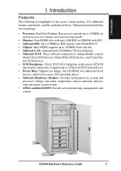
... uses the 440BX chipset from a third party) Ethernet Card: (optional ASUS PCI-L101) RAID Card: (optional ASUS PCI-DA2100A) 8 AP2000 Hardware Reference Guide I . Introduction I . This will save a great deal of time by yourself, it is a department server configured on the ASUS P2B-DS smart motherboard which supports the Pentium II processor and 100MHz front side...
... uses the 440BX chipset from a third party) Ethernet Card: (optional ASUS PCI-L101) RAID Card: (optional ASUS PCI-DA2100A) 8 AP2000 Hardware Reference Guide I . Introduction I . This will save a great deal of time by yourself, it is a department server configured on the ASUS P2B-DS smart motherboard which supports the Pentium II processor and 100MHz front side...
Hardware Reference
Page 9
... system and processor voltages, fan status, temperature, chassis intrusion, and provides automatic system restart. • ASMA and Intel LDSM: Provides server monitoring, management, and control. I . AP2000 Hardware Reference Guide 9 Introduction I . For additional features and details, read the motherboard User's Manual included with this server's many features.
... system and processor voltages, fan status, temperature, chassis intrusion, and provides automatic system restart. • ASMA and Intel LDSM: Provides server monitoring, management, and control. I . AP2000 Hardware Reference Guide 9 Introduction I . For additional features and details, read the motherboard User's Manual included with this server's many features.
Hardware Reference
Page 10
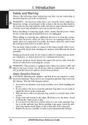
...cable and plug for the system unit and all power cables from the electrical outlet before relocating the system. Static-Sensitive Devices CAUTION: Motherboards, adapters, and disk drives are sensitive to prevent this damage. When adding or removing any time you are unplugged. If possible, disconnect...devices are ready to install the device in the system unit. • With the device still in order to prevent permanent damage. 10 AP2000 Hardware Reference Guide Hold drives by the edges. Use one hand, when possible, to connect or disconnect signal cables to prevent a possible...
...cable and plug for the system unit and all power cables from the electrical outlet before relocating the system. Static-Sensitive Devices CAUTION: Motherboards, adapters, and disk drives are sensitive to prevent this damage. When adding or removing any time you are unplugged. If possible, disconnect...devices are ready to install the device in the system unit. • With the device still in order to prevent permanent damage. 10 AP2000 Hardware Reference Guide Hold drives by the edges. Use one hand, when possible, to connect or disconnect signal cables to prevent a possible...
Hardware Reference
Page 11
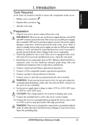
Unpack your server, do not bypass the grounding plug. Connect a Keyboard and Mouse (purchased separately) 5. AP2000 Hardware Reference Guide 11 Unlock the padlock if one is equipped with your server, do not connect the power cord. This server is installed...to work, and therefore removing the power cord is used. Connect a VGA-compatible monitor (purchased separately) 6. Set the power supply input voltage to your motherboard manual in this hardware reference guide along with a lockable front door to a grounded (three pronged) AC power source such as CPU, Memory, Hard ...
Unpack your server, do not bypass the grounding plug. Connect a Keyboard and Mouse (purchased separately) 5. AP2000 Hardware Reference Guide 11 Unlock the padlock if one is equipped with your server, do not connect the power cord. This server is installed...to work, and therefore removing the power cord is used. Connect a VGA-compatible monitor (purchased separately) 6. Set the power supply input voltage to your motherboard manual in this hardware reference guide along with a lockable front door to a grounded (three pronged) AC power source such as CPU, Memory, Hard ...
Hardware Reference
Page 13
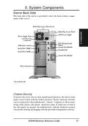
...Security To protect the server chassis from unauthorized intrusion, the chassis front panel can provide alerting and logging with the built-in keylock. AP2000 Hardware Reference Guide 13 System Components Server Back Side The back side of the server is provided to allow monitoring of the side ...panels are opened, the motherboard's onboard hardware monitor can be connected to the motherboard's "chassis" connector to show the back exterior components of this server. II. If either one or both of ...
...Security To protect the server chassis from unauthorized intrusion, the chassis front panel can provide alerting and logging with the built-in keylock. AP2000 Hardware Reference Guide 13 System Components Server Back Side The back side of the server is provided to allow monitoring of the side ...panels are opened, the motherboard's onboard hardware monitor can be connected to the motherboard's "chassis" connector to show the back exterior components of this server. II. If either one or both of ...
Hardware Reference
Page 14
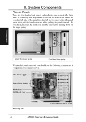
...Each panel is secured by pushing down on each side. To open the left side of the server. ATX Power Supply Internal Fan Module Motherboard SCSI RAID Card Server left panel removed, you should see the left view), remove the side panel screw, then pull the handle outward while... pulling the panel forward. Components Front door hinge spring Front door hinge spring With the left side Chassis Intrusion Micro Switch 14 AP2000 Hardware Reference Guide System Components Chassis Panels There are two identical side panels on the chassis, one on the hinge spring. II. II....
...Each panel is secured by pushing down on each side. To open the left side of the server. ATX Power Supply Internal Fan Module Motherboard SCSI RAID Card Server left panel removed, you should see the left view), remove the side panel screw, then pull the handle outward while... pulling the panel forward. Components Front door hinge spring Front door hinge spring With the left side Chassis Intrusion Micro Switch 14 AP2000 Hardware Reference Guide System Components Chassis Panels There are two identical side panels on the chassis, one on the hinge spring. II. II....
Hardware Reference
Page 24
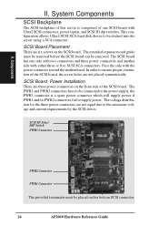
... three power connectors on the SCSI board. SCSI Board Power Installation There are six screws on the front side of this bottom SCSI connector. 24 AP2000 Hardware Reference Guide The extended expansion card guide must be removed. Face the side with Ultra2 SCSI connectors, power inputs, and SCSI ID dip switches.... II. System Components SCSI Backplane The SCSI backplane of the SCSI board. The SCSI board has one SCSI board with the power connector toward the motherboard.
... three power connectors on the SCSI board. SCSI Board Power Installation There are six screws on the front side of this bottom SCSI connector. 24 AP2000 Hardware Reference Guide The extended expansion card guide must be removed. Face the side with Ultra2 SCSI connectors, power inputs, and SCSI ID dip switches.... II. System Components SCSI Backplane The SCSI backplane of the SCSI board. The SCSI board has one SCSI board with the power connector toward the motherboard.
Hardware Reference
Page 27
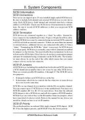
...SCSI ID number (ID 0 to work properly. Some use jumpers, others have a unique address (or SCSI ID). Internal devices connect to this motherboard with cables to 15 user installed single-ended SCSI devices. External SCSI devices may be on the last connector. The SCSI ID serves two purposes... onboard SCSI chipset is not in a "chain" by jumpers or dip switches. Note that you can connect up to form a "chain." AP2000 Hardware Reference Guide 27 II. Components II. You must always be connected using a terminator on another channel. If there are more devices try ...
...SCSI ID number (ID 0 to work properly. Some use jumpers, others have a unique address (or SCSI ID). Internal devices connect to this motherboard with cables to 15 user installed single-ended SCSI devices. External SCSI devices may be on the last connector. The SCSI ID serves two purposes... onboard SCSI chipset is not in a "chain" by jumpers or dip switches. Note that you can connect up to form a "chain." AP2000 Hardware Reference Guide 27 II. Components II. You must always be connected using a terminator on another channel. If there are more devices try ...
Hardware Reference
Page 28
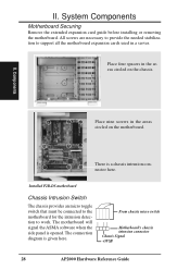
...when the side panel is given here. From chassis micro switch Motherboard's chassis intrusion connector Chassis Signal +5VSB 28 AP2000 Hardware Reference Guide System Components Motherboard Securing Remove the extended expansion card guide before installing or removing the motherboard. II. Components Place nine screws in the areas circled on...All screws are necessary to provide the needed stabilization to work. Place four spacers in a server. II. Installed P2B-DS motherboard Chassis Intrusion Switch The chassis provides an micro toggle switch that must be connected to the...
...when the side panel is given here. From chassis micro switch Motherboard's chassis intrusion connector Chassis Signal +5VSB 28 AP2000 Hardware Reference Guide System Components Motherboard Securing Remove the extended expansion card guide before installing or removing the motherboard. II. Components Place nine screws in the areas circled on...All screws are necessary to provide the needed stabilization to work. Place four spacers in a server. II. Installed P2B-DS motherboard Chassis Intrusion Switch The chassis provides an micro toggle switch that must be connected to the...
Hardware Reference
Page 29
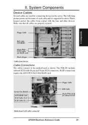
... keepers protect the cables from devices Cable Connections The cables connect to the motherboard as shown. Make sure that all cables are used for RAID card) Plastic Keeper Cables from contact with cables connected AP2000 Hardware Reference Guide 29 Floppy Cable IDE Cable (CD-ROM) 68-pin ...WideSCSI Cables (for connecting devices in the server. RAID connections require the ASUS PCI-DA2100A RAID card. The P2B-DS includes onboard SCSI ...
... keepers protect the cables from devices Cable Connections The cables connect to the motherboard as shown. Make sure that all cables are used for RAID card) Plastic Keeper Cables from contact with cables connected AP2000 Hardware Reference Guide 29 Floppy Cable IDE Cable (CD-ROM) 68-pin ...WideSCSI Cables (for connecting devices in the server. RAID connections require the ASUS PCI-DA2100A RAID card. The P2B-DS includes onboard SCSI ...
Hardware Reference
Page 31
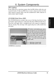
CD-ROM Disk Drive (IDE) The CD-ROM disk drive mounts only in case you install an audio card. Remove unused cables from the motherboard's IDE connector to your audio card. CD audio output CD-ROM drive connections NOTE: A CD-ROM audio cable is used, connect it to only ... travels through the signal cable. Computer CDROMs have data (such as *.wav, *.mpg, *.avi) that of the cable. The red stripe of power cable AP2000 Hardware Reference Guide 31 Components II. The only function of the audio cable is straightforward with connectors designed to the end of IDE hard disk...
CD-ROM Disk Drive (IDE) The CD-ROM disk drive mounts only in case you install an audio card. Remove unused cables from the motherboard's IDE connector to your audio card. CD audio output CD-ROM drive connections NOTE: A CD-ROM audio cable is used, connect it to only ... travels through the signal cable. Computer CDROMs have data (such as *.wav, *.mpg, *.avi) that of the cable. The red stripe of power cable AP2000 Hardware Reference Guide 31 Components II. The only function of the audio cable is straightforward with connectors designed to the end of IDE hard disk...

Hardware Reference
Page 33
...- Expansion Card Installation Procedure: 1. Remove the side panel to the expansion slot with the expansion slot on the mother- Secure the card to the chassis. 4. AP2000 Hardware Reference Guide 33 vices and remove the main power cord. 3. Attach cables or wires if necessary. 9. Find an unused expansion slot on the...
...- Expansion Card Installation Procedure: 1. Remove the side panel to the expansion slot with the expansion slot on the mother- Secure the card to the chassis. 4. AP2000 Hardware Reference Guide 33 vices and remove the main power cord. 3. Attach cables or wires if necessary. 9. Find an unused expansion slot on the...
Hardware Reference
Page 34
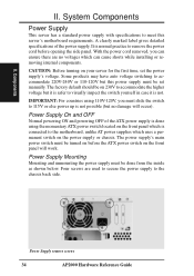
...can ensure there are used to secure the power supply to the motherboard, unlike AT power supplies which is not. The power supply's main power switch must be set the power supply's voltage. Power Supply remove screws 34 AP2000 Hardware Reference Guide System Components Power Supply This server has a ... the higher voltage but this power supply must slide the switch to 115V or else power up is normal practice to meet this server's motherboard requirements. Power Supply On and OFF Normal powering ON and powering OFF of the power supply. CAUTION: Before turning on the front panel...
...can ensure there are used to secure the power supply to the motherboard, unlike AT power supplies which is not. The power supply's main power switch must be set the power supply's voltage. Power Supply remove screws 34 AP2000 Hardware Reference Guide System Components Power Supply This server has a ... the higher voltage but this power supply must slide the switch to 115V or else power up is normal practice to meet this server's motherboard requirements. Power Supply On and OFF Normal powering ON and powering OFF of the power supply. CAUTION: Before turning on the front panel...
Hardware Reference
Page 36
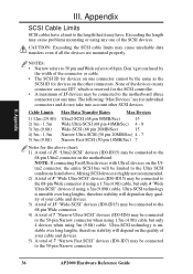
...The SCSI ID for the SCSI controller. • A maximum of 7 "Narrow Fast SCSI" devices (ID0-ID7) may be connected to the motherboard (three connectors) at one time. The following "Max Devices" are mounted properly. Appendix III. NOTE: If connecting Fast/Ultra devices with Ultra2 devices...connectors and do not take into account other connectors. Exceeding the length may be connected to the 50-pin Narrow connector. 36 AP2000 Hardware Reference Guide Ultra-SCSI technology is unstable over long lengths, therefore stability will be limited to the Ultra SCSI conditions listed ...
...The SCSI ID for the SCSI controller. • A maximum of 7 "Narrow Fast SCSI" devices (ID0-ID7) may be connected to the motherboard (three connectors) at one time. The following "Max Devices" are mounted properly. Appendix III. NOTE: If connecting Fast/Ultra devices with Ultra2 devices...connectors and do not take into account other connectors. Exceeding the length may be connected to the 50-pin Narrow connector. 36 AP2000 Hardware Reference Guide Ultra-SCSI technology is unstable over long lengths, therefore stability will be limited to the Ultra SCSI conditions listed ...
Hardware Reference
Page 38
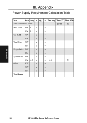
Appendix Power Supply Requirement Calculation Table Item Volts Amp x Total Motherboard Power Hard Drive 5.0V 1.3 x 12V 1.5 x CD-ROM 5.0V x 12V x Tape Drive 5.0V x 12V x Floppy Drive 5.0V x 12V x System Fans 5.0V x 12V 0.3 x Other 3.3V x 5.0V x 12V x Total Power Qty. = TotalAmp Watts (5V) Watts (12V) 209.55 3.6 = = = = = = = = = = 0.6 7.2 = = = III. III. Appendix 38 AP2000 Hardware Reference Guide
Appendix Power Supply Requirement Calculation Table Item Volts Amp x Total Motherboard Power Hard Drive 5.0V 1.3 x 12V 1.5 x CD-ROM 5.0V x 12V x Tape Drive 5.0V x 12V x Floppy Drive 5.0V x 12V x System Fans 5.0V x 12V 0.3 x Other 3.3V x 5.0V x 12V x Total Power Qty. = TotalAmp Watts (5V) Watts (12V) 209.55 3.6 = = = = = = = = = = 0.6 7.2 = = = III. III. Appendix 38 AP2000 Hardware Reference Guide
Hardware Reference
Page 40
... Interface) High speed parallel interface defined by the X3T9.2 committee of specialized tasks. III. Peripherals are based on ATX motherboards. PS/2 Port PS/2 ports are attached to store permanent programs (called firmware) used on IBM's Micro Channel Architecture. The ...UPS (Uninterruptible Power Supply) A battery system that offers protection against transient power conditions and short-term power outages. 40 AP2000 Hardware Reference Guide Appendix III. Appendix Peripherals Peripherals are several different types of architecture transfers data through the POST, a series...
... Interface) High speed parallel interface defined by the X3T9.2 committee of specialized tasks. III. Peripherals are based on ATX motherboards. PS/2 Port PS/2 ports are attached to store permanent programs (called firmware) used on IBM's Micro Channel Architecture. The ...UPS (Uninterruptible Power Supply) A battery system that offers protection against transient power conditions and short-term power outages. 40 AP2000 Hardware Reference Guide Appendix III. Appendix Peripherals Peripherals are several different types of architecture transfers data through the POST, a series...

