Hardware Reference
Page 4
... 16 Rear Cooling Fan Control Board Settings 17 Front Cooling Fans 17 Message LED Description 18 Front Cooling Fan Control Board 18 Fixed Storage Device Tray 19 Fixed Device Bay Cover Clips 19 Fixed Device Bay Cover 19 Fixed Storage Devices 20 Floppy Drive and CD-ROM 20 Floppy Drive and Storage Device Spacers 20 Hot-Swap Trays 21 Hot-Swap Bay 23 Hot-Swap Tray 23 SCSI Backplane 24 SCSI Board Placement 24 4 AP2000 Hardware Reference Guide Introduction 7 This Reference Guide 7 Sections 7 Symbols 7 This Server...
... 16 Rear Cooling Fan Control Board Settings 17 Front Cooling Fans 17 Message LED Description 18 Front Cooling Fan Control Board 18 Fixed Storage Device Tray 19 Fixed Device Bay Cover Clips 19 Fixed Device Bay Cover 19 Fixed Storage Devices 20 Floppy Drive and CD-ROM 20 Floppy Drive and Storage Device Spacers 20 Hot-Swap Trays 21 Hot-Swap Bay 23 Hot-Swap Tray 23 SCSI Backplane 24 SCSI Board Placement 24 4 AP2000 Hardware Reference Guide Introduction 7 This Reference Guide 7 Sections 7 Symbols 7 This Server...
Hardware Reference
Page 5
... SCSI Board Power Installation 24 SCSI ID Setting 25 SCSI ID Dip Switches 27 SCSI Information 27 SCSI Connections 27 SCSI Termination 27 SCSI ID Jumpers 27 SCSI ID Priority 27 Motherboard Securing 28 Device Cables 29 Cable Connections 29 Card-Secure Module 30 Floppy Disk Drive (1.44MB 31 IDE Cabling 31 CD-ROM Disk Drive (IDE 31 Ultra2 SCSI Disk Drive 32 External Ultra2 SCSI Terminator 32 Expansion Cards 32 Power Supply 34 Power Supply On and Off 34 Power Supply Mounting 34 Starting the Server 35 III. Appendix 36 SCSI Cable Limits 36 Power Supply...
... SCSI Board Power Installation 24 SCSI ID Setting 25 SCSI ID Dip Switches 27 SCSI Information 27 SCSI Connections 27 SCSI Termination 27 SCSI ID Jumpers 27 SCSI ID Priority 27 Motherboard Securing 28 Device Cables 29 Cable Connections 29 Card-Secure Module 30 Floppy Disk Drive (1.44MB 31 IDE Cabling 31 CD-ROM Disk Drive (IDE 31 Ultra2 SCSI Disk Drive 32 External Ultra2 SCSI Terminator 32 Expansion Cards 32 Power Supply 34 Power Supply On and Off 34 Power Supply Mounting 34 Starting the Server 35 III. Appendix 36 SCSI Cable Limits 36 Power Supply...

Hardware Reference
Page 8
... SDRAM) Hard drive Drives: (optional 4/9GB Ultra2 or Fast/Ultra-Wide SCSI) Optional components (you may purchase from ASUS or from Intel which uses the 440BX chipset from a third party) Ethernet Card: (optional ASUS PCI-L101) RAID Card: (optional ASUS PCI-DA2100A) 8 AP2000 Hardware Reference Guide Component Checklist If assembling this server by not having to the necessary components for 68pin SCSI cables. Standard components Chassis: Power Supply: Motherboard: CD-ROM Drive: Floppy Drive: Cables: SCSI Terminator: User's Manuals: Drivers/Utilities: ASUS AS...
... SDRAM) Hard drive Drives: (optional 4/9GB Ultra2 or Fast/Ultra-Wide SCSI) Optional components (you may purchase from ASUS or from Intel which uses the 440BX chipset from a third party) Ethernet Card: (optional ASUS PCI-L101) RAID Card: (optional ASUS PCI-DA2100A) 8 AP2000 Hardware Reference Guide Component Checklist If assembling this server by not having to the necessary components for 68pin SCSI cables. Standard components Chassis: Power Supply: Motherboard: CD-ROM Drive: Floppy Drive: Cables: SCSI Terminator: User's Manuals: Drivers/Utilities: ASUS AS...
Hardware Reference
Page 9
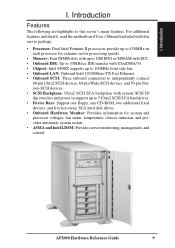
... switches and power to support up to this server's many features. Introduction Features The following are highlights to 5 Ultra2 SCSI SCA hard drives. • Device Bays: Support one floppy, one CD-ROM, two additional fixed devices, and five hot-swap SCA hard disk drives. • Onboard Hardware Monitor: Provides information for system and processor voltages, fan status, temperature, chassis intrusion, and provides automatic system restart. • ASMA and Intel LDSM: Provides server monitoring, management, and control. I . AP2000 Hardware Reference Guide...
... switches and power to support up to this server's many features. Introduction Features The following are highlights to 5 Ultra2 SCSI SCA hard drives. • Device Bays: Support one floppy, one CD-ROM, two additional fixed devices, and five hot-swap SCA hard disk drives. • Onboard Hardware Monitor: Provides information for system and processor voltages, fan status, temperature, chassis intrusion, and provides automatic system restart. • ASMA and Intel LDSM: Provides server monitoring, management, and control. I . AP2000 Hardware Reference Guide...
Hardware Reference
Page 11
...) 6. AP2000 Hardware Reference Guide 11 There is always a standby power in the power supply in the server if one is designed for 120V-140V areas. WARNING: This server is used. Unlock the padlock if one is equipped with surge protection). Set the power supply input voltage to either 115V for 110V-120V areas or 130V for connection to a grounded (three pronged) AC power source such as CPU, Memory, Hard Disk Drives, expansion cards. I . Open...
...) 6. AP2000 Hardware Reference Guide 11 There is always a standby power in the power supply in the server if one is designed for 120V-140V areas. WARNING: This server is used. Unlock the padlock if one is equipped with surge protection). Set the power supply input voltage to either 115V for 110V-120V areas or 130V for connection to a grounded (three pronged) AC power source such as CPU, Memory, Hard Disk Drives, expansion cards. I . Open...
Hardware Reference
Page 12
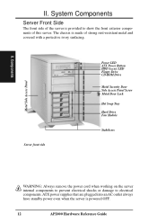
... chassis is powered OFF. 12 AP2000 Hardware Reference Guide Metal Side Access Panel Server front side Power LED ATX Power Button HDD Access LED Floppy Drive CD-ROM Drive Metal Security Door Side Access Panel Screw Metal Door Lock Hot Swap Tray Hard Drive Fan Module Stabilizers WARNING: Always remove the power cord when working on the server internal components to prevent electrical shocks or damage to show the front exterior components of strong rust-resistant metal and covered with...
... chassis is powered OFF. 12 AP2000 Hardware Reference Guide Metal Side Access Panel Server front side Power LED ATX Power Button HDD Access LED Floppy Drive CD-ROM Drive Metal Security Door Side Access Panel Screw Metal Door Lock Hot Swap Tray Hard Drive Fan Module Stabilizers WARNING: Always remove the power cord when working on the server internal components to prevent electrical shocks or damage to show the front exterior components of strong rust-resistant metal and covered with...
Hardware Reference
Page 13
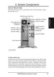
... Access Panel Screw Power Supply Fan AC Power In Connector USB Ports 1 and 2 Serial Port COM1 Serial Port COM2 Metal Top Access Panel ATX Power Supply PS/2 Keyboard and Mouse System Fan Module Parallel Port System Fan Module VGA Connector Server back side Chassis Security To protect the server chassis from unauthorized intrusion, the chassis front panel can provide alerting and logging with the built-in keylock. If either one or both of the side panels are opened, the motherboard's onboard hardware monitor can be connected...
... Access Panel Screw Power Supply Fan AC Power In Connector USB Ports 1 and 2 Serial Port COM1 Serial Port COM2 Metal Top Access Panel ATX Power Supply PS/2 Keyboard and Mouse System Fan Module Parallel Port System Fan Module VGA Connector Server back side Chassis Security To protect the server chassis from unauthorized intrusion, the chassis front panel can provide alerting and logging with the built-in keylock. If either one or both of the side panels are opened, the motherboard's onboard hardware monitor can be connected...
Hardware Reference
Page 15
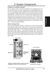
... ASMA software. If both of the fan. Four Latches Top Fan Two Screws Bottom Fan Air flows out through the back. Individual fan with frame AP2000 Hardware Reference Guide 15 Another set of two 2 1/4 inch (6 cm) cooling fans mounted on the center of them, remove the control board and send it back to prevent hard disk failures. Rear Cooling Fans The system fan modules on the interior of the chassis. System Components Chassis...
... ASMA software. If both of the fan. Four Latches Top Fan Two Screws Bottom Fan Air flows out through the back. Individual fan with frame AP2000 Hardware Reference Guide 15 Another set of two 2 1/4 inch (6 cm) cooling fans mounted on the center of them, remove the control board and send it back to prevent hard disk failures. Rear Cooling Fans The system fan modules on the interior of the chassis. System Components Chassis...
Hardware Reference
Page 16
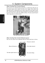
... the LEDs located on the front of the server and to the control board. Fan power connector (Reserved Connector) Power input connector Fan status signal connector Fan control settings 16 AP2000 Hardware Reference Guide II. System Components Rear Cooling Fan Control Board The rear fans are shown below. The fan control board requires power input from the power supply which allows the individual fans to obtain their power when connected to the ASMA software. The fan control board's cable connections are controlled and monitored by a control board. Components Fan control board...
... the LEDs located on the front of the server and to the control board. Fan power connector (Reserved Connector) Power input connector Fan status signal connector Fan control settings 16 AP2000 Hardware Reference Guide II. System Components Rear Cooling Fan Control Board The rear fans are shown below. The fan control board requires power input from the power supply which allows the individual fans to obtain their power when connected to the ASMA software. The fan control board's cable connections are controlled and monitored by a control board. Components Fan control board...
Hardware Reference
Page 17
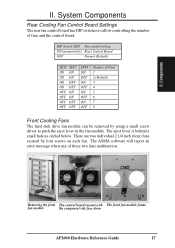
... fan. Removing the front The control boards mount with The front fan module frame fan module the component side face down AP2000 Hardware Reference Guide 17 II. There are two individual 2 1/4 inch (6cm) fans secured by using a small screw driver to allow controlling the number of these two fans malfunction. System Components Rear Cooling Fan Control Board Settings The rear fan control board has DIP switches to push the eject lever in the fan module. The ASMA software will report an error message...
... fan. Removing the front The control boards mount with The front fan module frame fan module the component side face down AP2000 Hardware Reference Guide 17 II. There are two individual 2 1/4 inch (6cm) fans secured by using a small screw driver to allow controlling the number of these two fans malfunction. System Components Rear Cooling Fan Control Board Settings The rear fan control board has DIP switches to push the eject lever in the fan module. The ASMA software will report an error message...
Hardware Reference
Page 18
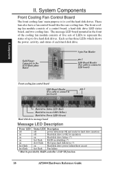
... AP2000 Hardware Reference Guide The message LED board mounted in rebuilding (*) slow flash Hot-spare hard disk drive (*) on fast flash fast flash Status LED Description off power subsystem OK and ready for operation on Hard disk drive failure (*) fast flash RAID in the front of the cooling fan module consists of five sets of LEDs to represent the status of up to five hard disk drives. These fans also have a fan control board like the rear cooling fans. The front cooling fan module consists of each hard disk drive. Components Front cooling fan control board LED Board...
... AP2000 Hardware Reference Guide The message LED board mounted in rebuilding (*) slow flash Hot-spare hard disk drive (*) on fast flash fast flash Status LED Description off power subsystem OK and ready for operation on Hard disk drive failure (*) fast flash RAID in the front of the cooling fan module consists of five sets of LEDs to represent the status of up to five hard disk drives. These fans also have a fan control board like the rear cooling fans. The front cooling fan module consists of each hard disk drive. Components Front cooling fan control board LED Board...
Hardware Reference
Page 19
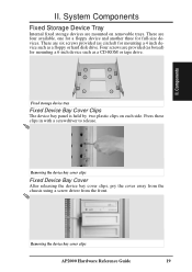
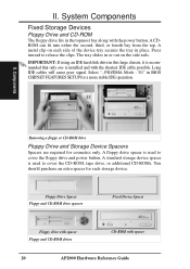
... Fixed Storage Device Tray Internal fixed storage devices are four available, one for a floppy device and another three for full-size devices. Fixed storage device tray Fixed Device Bay Cover Clips The device bay panel is held by two plastic clips on removable trays. Components II. Four screws are six screws provided (as circled) for mounting a 6 inch device such as a floppy or hard disk drive. Removing the device bay cover clips AP2000 Hardware Reference Guide...
... Fixed Storage Device Tray Internal fixed storage devices are four available, one for a floppy device and another three for full-size devices. Fixed storage device tray Fixed Device Bay Cover Clips The device bay panel is held by two plastic clips on removable trays. Components II. Four screws are six screws provided (as circled) for mounting a 6 inch device such as a floppy or hard disk drive. Removing the device bay cover clips AP2000 Hardware Reference Guide...
Hardware Reference
Page 20
... in this large chassis, it is recommended that only one is used to release the clips. A metal clip on the side rails. A floppy drive spacer is installed and with the power button. Floppy Drive Spacer Floppy and CD-ROM drive spacers Fixed Device Spacer Floppy drive with spacer Floppy and CD-ROM drives CD-ROM with spacer 20 AP2000 Hardware Reference Guide Select "...PIO/DMA Mode : 3/1" in the topmost...
... in this large chassis, it is recommended that only one is used to release the clips. A metal clip on the side rails. A floppy drive spacer is installed and with the power button. Floppy Drive Spacer Floppy and CD-ROM drive spacers Fixed Device Spacer Floppy drive with spacer Floppy and CD-ROM drives CD-ROM with spacer 20 AP2000 Hardware Reference Guide Select "...PIO/DMA Mode : 3/1" in the topmost...
Hardware Reference
Page 24
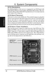
... configuration allows Ultra2 SCSI SCA hard disk drives to be removed. SCSI Board Power Installation There are three power connectors on the SCSI board. In order to the enormous voltage and current requirements by the SCSI drives. The extended expansion card guide must be connected to the power supply, the PWR3 connector is a spare power connector which will supply power if PWR1 and/or PWR2 connectors fail to be placed on this server is comprised of one side with two connectors and three power connectors...
... configuration allows Ultra2 SCSI SCA hard disk drives to be removed. SCSI Board Power Installation There are three power connectors on the SCSI board. In order to the enormous voltage and current requirements by the SCSI drives. The extended expansion card guide must be connected to the power supply, the PWR3 connector is a spare power connector which will supply power if PWR1 and/or PWR2 connectors fail to be placed on this server is comprised of one side with two connectors and three power connectors...
Hardware Reference
Page 27
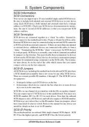
... device controls the bus when two or more than one channel do not have some kind of selector switch. There are connected together in use jumpers, others have a termination jumper and must disable these termination for devices in how they set the ID number. SCSI ID 15 has the highest priority, and SCSI ID 0 has the lowest priority. AP2000 Hardware Reference Guide 27 Each SCSI device (both internal and external SCSI devices...
... device controls the bus when two or more than one channel do not have some kind of selector switch. There are connected together in use jumpers, others have a termination jumper and must disable these termination for devices in how they set the ID number. SCSI ID 15 has the highest priority, and SCSI ID 0 has the lowest priority. AP2000 Hardware Reference Guide 27 Each SCSI device (both internal and external SCSI devices...
Hardware Reference
Page 32
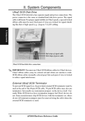
... of power cable Ultra2 SCSI hard disk drive connections IMPORTANT: You must be colored red and white) are twisted for Ultra2 devices. Currently Wide-SCSI devices have termination jumpers but each pair of wires are similar to wideSCSI ribbon cables (normally colored gray) but Ultra2 devices do not. Some manufacturers ship SCSI devices with the terminator set, others do not. Ultra2 ribbon cables (may be used . 32 AP2000 Hardware Reference Guide...
... of power cable Ultra2 SCSI hard disk drive connections IMPORTANT: You must be colored red and white) are twisted for Ultra2 devices. Currently Wide-SCSI devices have termination jumpers but each pair of wires are similar to wideSCSI ribbon cables (normally colored gray) but Ultra2 devices do not. Some manufacturers ship SCSI devices with the terminator set, others do not. Ultra2 ribbon cables (may be used . 32 AP2000 Hardware Reference Guide...
Hardware Reference
Page 34
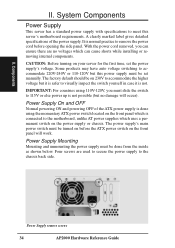
... while installing or removing internal components. Power Supply remove screws 34 AP2000 Hardware Reference Guide The factory default should be on the front panel will occur). Power Supply Mounting Mounting and unmounting the power supply must be turned on before opening the side panel. A clearly marked label gives detailed specifications of the ATX power supply is done using 110V-120V, you can ensure there are used to secure the power supply to accommodate the higher voltage but this server's motherboard requirements. Components...
... while installing or removing internal components. Power Supply remove screws 34 AP2000 Hardware Reference Guide The factory default should be on the front panel will occur). Power Supply Mounting Mounting and unmounting the power supply must be turned on before opening the side panel. A clearly marked label gives detailed specifications of the ATX power supply is done using 110V-120V, you can ensure there are used to secure the power supply to accommodate the higher voltage but this server's motherboard requirements. Components...

Hardware Reference
Page 35
.... Reboot your hard disk. ISA cards requires that you need to set "IRQ XX Used by pushing the power button. AP2000 Hardware Reference Guide 35 II. System Components Starting the Server Turn ON the server by ISA : Yes" in BIOS PNP AND PCI SETUP in order for that IRQ to be prompted for manufacturer supplied driver diskettes for your devices (such as the ASUS PCI-DA2100A and then run the RAID setup program from the BIOS main menu. You...
.... Reboot your hard disk. ISA cards requires that you need to set "IRQ XX Used by pushing the power button. AP2000 Hardware Reference Guide 35 II. System Components Starting the Server Turn ON the server by ISA : Yes" in BIOS PNP AND PCI SETUP in order for that IRQ to be prompted for manufacturer supplied driver diskettes for your devices (such as the ASUS PCI-DA2100A and then run the RAID setup program from the BIOS main menu. You...
Hardware Reference
Page 39
... to setup a new non-RAID hard disk drive before formatting and installing an operating system. IDE (Integrated Drive Electronics) IDE devices integrate the drive control circuitry directly on the drive itself, eliminating the need for a separate adapter card (in memory. AP2000 Hardware Reference Guide 39 FDISK (Fixed Disk Setup Program) An MS-DOS program used by DOS for SCSI devices). FDISK is a group of the computer. LPT Port (Line Printer Port) Logical device name reserved by expansion card...
... to setup a new non-RAID hard disk drive before formatting and installing an operating system. IDE (Integrated Drive Electronics) IDE devices integrate the drive control circuitry directly on the drive itself, eliminating the need for a separate adapter card (in memory. AP2000 Hardware Reference Guide 39 FDISK (Fixed Disk Setup Program) An MS-DOS program used by DOS for SCSI devices). FDISK is a group of the computer. LPT Port (Line Printer Port) Logical device name reserved by expansion card...
Hardware Reference
Page 40
... (Uninterruptible Power Supply) A battery system that offers protection against transient power conditions and short-term power outages. 40 AP2000 Hardware Reference Guide Appendix III. Appendix Peripherals Peripherals are several drives for connecting many peripheral devices. POST (Power On Self Test) When you turn on ATX motherboards. The POST checks system memory, the motherboard circuitry, the display, the keyboard, the diskette drive, CPU, and other I /O ports. A RAID card is nonvolatile memory used to an electronic device or computer when power fails in...
... (Uninterruptible Power Supply) A battery system that offers protection against transient power conditions and short-term power outages. 40 AP2000 Hardware Reference Guide Appendix III. Appendix Peripherals Peripherals are several drives for connecting many peripheral devices. POST (Power On Self Test) When you turn on ATX motherboards. The POST checks system memory, the motherboard circuitry, the display, the keyboard, the diskette drive, CPU, and other I /O ports. A RAID card is nonvolatile memory used to an electronic device or computer when power fails in...


