
Motherboard DIY Troubleshooting Guide
Page 87
Change Option F1 General Help F10 Save and Exit ESC Exit v02.58 (C)Copyright 1985-2004, American Megatrends, Inc. 4-29 Advanced BIOS SETUP UTILITY USB Configuration Module Version - 2.24.0-10.4 USB Devices Enabled: None Options Enabled Disabled USB Controller Legacy USB Support USB 2.0 Controller Mode BIOS EHCI Hand-off [USB1.1+2.0] [Auto] [HiSpeed] [Enabled] USB Mass Storage Device Configuration Select Screen Select Item +- POST Check LAN Cable LAN Cable Status Pair Status Length 1-2 Open 3-6 Open 4-5 Open 7-8 Open 0.0M 0.0M 0.0M 0.0M [Disabled] Check LAN cable ...
Change Option F1 General Help F10 Save and Exit ESC Exit v02.58 (C)Copyright 1985-2004, American Megatrends, Inc. 4-29 Advanced BIOS SETUP UTILITY USB Configuration Module Version - 2.24.0-10.4 USB Devices Enabled: None Options Enabled Disabled USB Controller Legacy USB Support USB 2.0 Controller Mode BIOS EHCI Hand-off [USB1.1+2.0] [Auto] [HiSpeed] [Enabled] USB Mass Storage Device Configuration Select Screen Select Item +- POST Check LAN Cable LAN Cable Status Pair Status Length 1-2 Open 3-6 Open 4-5 Open 7-8 Open 0.0M 0.0M 0.0M 0.0M [Disabled] Check LAN cable ...
A8R-MVP User's Manual for English Edtion
Page 5
... JumperFree Configuration 4-18 4.4.2 CPU Configuration 4-22 4.4.3 Chipset Configuration 4-26 4.4.4 Onboard Devices Configuration 4-27 4.4.5 PCI PnP 4-29 4.4.6 LAN Cable Status 4-30 4.4.7 USB Configuration 4-30 4.5 Power menu 4-32 4.5.1 Suspend Mode 4-32 4.5.2 Repost Video on S3 Resume 4-32 4.5.3 ACPI 2.0 Support 4-32 4.5.4 ACPI APIC Support 4-32 4.5.5 APM Configuration 4-33 4.5.6 Hardware Monitor 4-35 4.6 Boot menu 4-37 4.6.1 Boot Device Priority 4-38 4.6.2 Boot Settings Configuration 4-39 4.6.3 Security 4-40 4.7 Exit menu 4-42 Chapter 5: Software support 5.1 Installing an...
... JumperFree Configuration 4-18 4.4.2 CPU Configuration 4-22 4.4.3 Chipset Configuration 4-26 4.4.4 Onboard Devices Configuration 4-27 4.4.5 PCI PnP 4-29 4.4.6 LAN Cable Status 4-30 4.4.7 USB Configuration 4-30 4.5 Power menu 4-32 4.5.1 Suspend Mode 4-32 4.5.2 Repost Video on S3 Resume 4-32 4.5.3 ACPI 2.0 Support 4-32 4.5.4 ACPI APIC Support 4-32 4.5.5 APM Configuration 4-33 4.5.6 Hardware Monitor 4-35 4.6 Boot menu 4-37 4.6.1 Boot Device Priority 4-38 4.6.2 Boot Settings Configuration 4-39 4.6.3 Security 4-40 4.7 Exit menu 4-42 Chapter 5: Software support 5.1 Installing an...
A8R-MVP User's Manual for English Edtion
Page 6
...10 Using the Virtual Cable Tester 5-10 5.3.3 ASUS PC Probe II 5-11 5.3.4 Cool 'n' Quiet™ Technology 5-17 5.3.5 SoundMAX® High Definition Audio utility 5-19 Audio Setup Wizard 5-20 5.4 RAID configurations 5-24 5.4.1 Installing hard disks 5-25 5.4.2 ULI® RAID configurations 5-25 5.5 Creating a RAID driver disk 5-33 Chapter 6: A T I® MVP technology support 6.1 Overview 6-1 6.2 Hardware installation 6-2 6.2.1 Installing a single graphics card 6-2 6.2.2 Installing CrossFire™ graphics cards 6-3 6.3 Software information 6-6 6.3.1 Installing the device drivers...
...10 Using the Virtual Cable Tester 5-10 5.3.3 ASUS PC Probe II 5-11 5.3.4 Cool 'n' Quiet™ Technology 5-17 5.3.5 SoundMAX® High Definition Audio utility 5-19 Audio Setup Wizard 5-20 5.4 RAID configurations 5-24 5.4.1 Installing hard disks 5-25 5.4.2 ULI® RAID configurations 5-25 5.5 Creating a RAID driver disk 5-33 Chapter 6: A T I® MVP technology support 6.1 Overview 6-1 6.2 Hardware installation 6-2 6.2.1 Installing a single graphics card 6-2 6.2.2 Installing CrossFire™ graphics cards 6-3 6.3 Software information 6-6 6.3.1 Installing the device drivers...
A8R-MVP User's Manual for English Edtion
Page 12
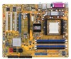
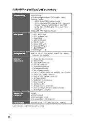
... mouse port 1 x PS/2 keyboard port 1 x Parallel port 1 x LAN (RJ-45) port 4 x USB 2.0 ports 1 x Serial (COM) port 1 x Coaxial S/PDIF port 1 x IEEE 1394a port 6-Channel audio ports Manageabiity WfM 2.0, DMI 2.0, WOL by PME, WOR by PME, chassis intrusion, PXE, and RPL Internal connectors 1 x Floppy disk drive connector 2 x IDE connectors 4 x Serial ATA connectors 1 x CPU fan connector 1 x Chassis fan connector 1 x Power fan connector 1 x IEEE 1394a connector 2 x USB 2.0 connectors for four additional USB 2.0 ports 1 x 24-pin EATX power connector 1 x 4-pin ATX 12 V power connector 1 x EZ Plug...
... mouse port 1 x PS/2 keyboard port 1 x Parallel port 1 x LAN (RJ-45) port 4 x USB 2.0 ports 1 x Serial (COM) port 1 x Coaxial S/PDIF port 1 x IEEE 1394a port 6-Channel audio ports Manageabiity WfM 2.0, DMI 2.0, WOL by PME, WOR by PME, chassis intrusion, PXE, and RPL Internal connectors 1 x Floppy disk drive connector 2 x IDE connectors 4 x Serial ATA connectors 1 x CPU fan connector 1 x Chassis fan connector 1 x Power fan connector 1 x IEEE 1394a connector 2 x USB 2.0 connectors for four additional USB 2.0 ports 1 x 24-pin EATX power connector 1 x 4-pin ATX 12 V power connector 1 x EZ Plug...
A8R-MVP User's Manual for English Edtion
Page 36
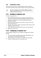
Align the card connector with the slot and press firmly until the card is already installed in a chassis). 3. Assign an IRQ to the tables on BIOS setup. 2. Before installing the expansion card, read the documentation that came with the screw you removed earlier. 6. Install the software drivers for information on the next page. 3. Keep the screw for the card. 2. Refer to the card. Make sure to use . 4. Failure to...
Align the card connector with the slot and press firmly until the card is already installed in a chassis). 3. Assign an IRQ to the tables on BIOS setup. 2. Before installing the expansion card, read the documentation that came with the screw you removed earlier. 6. Install the software drivers for information on the next page. 3. Keep the screw for the card. 2. Refer to the card. Make sure to use . 4. Failure to...
A8R-MVP User's Manual for English Edtion
Page 37
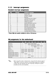
... Port (LPT1)* System CMOS/Real Time Clock IRQ holder for PCI steering* IRQ holder for PCI steering* IRQ holder for PCI steering* PS/2 Compatible Mouse Port* Numeric Data Processor Primary IDE/SATA Channel Secondary IDE/SATA Channel * These IRQs are usually available for this motherboard PCI slot 1 PCI slot 2 PCI slot 3 IEEE 1394 LAN PCI-E x1 PCI-E x16_1 PCI-E x16_2 Onboard USB controller 1 Onboard USB controller 2 Onboard USB controller 3 Onboard USB 2.0 controller HD audio A B C D E F G H - shared shared shared shared - - - - - shared - - shared - - - - - ASUS A8R-MVP...
... Port (LPT1)* System CMOS/Real Time Clock IRQ holder for PCI steering* IRQ holder for PCI steering* IRQ holder for PCI steering* PS/2 Compatible Mouse Port* Numeric Data Processor Primary IDE/SATA Channel Secondary IDE/SATA Channel * These IRQs are usually available for this motherboard PCI slot 1 PCI slot 2 PCI slot 3 IEEE 1394 LAN PCI-E x1 PCI-E x16_1 PCI-E x16_2 Onboard USB controller 1 Onboard USB controller 2 Onboard USB controller 3 Onboard USB 2.0 controller HD audio A B C D E F G H - shared shared shared shared - - - - - shared - - shared - - - - - ASUS A8R-MVP...
A8R-MVP User's Manual for English Edtion
Page 39
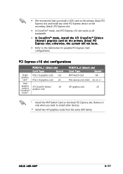
... card* Dual graphics cards in CrossFire™ mode** PCIEX16_1 (blue) slot Card Type Speed PCIe x16 graphics card x16 PCIe x16 graphics card x8 ATI CrossFire Edition x8 graphics card PCIEX16_2 (black) slot Card Type Speed MVP Switch Card NA PCIe devices (non-VGA) x8, x4, x1 ATI graphics card x8 * Install the MVP Switch Card on the primary (blue) PCI Express slot and install any other devices. ** Install two ATI graphics cards from the same GPU family. • We recommend that you want to the table below for possible PCI Express Card configurations. ASUS A8R-MVP...
... card* Dual graphics cards in CrossFire™ mode** PCIEX16_1 (blue) slot Card Type Speed PCIe x16 graphics card x16 PCIe x16 graphics card x8 ATI CrossFire Edition x8 graphics card PCIEX16_2 (black) slot Card Type Speed MVP Switch Card NA PCIe devices (non-VGA) x8, x4, x1 ATI graphics card x8 * Install the MVP Switch Card on the primary (blue) PCI Express slot and install any other devices. ** Install two ATI graphics cards from the same GPU family. • We recommend that you want to the table below for possible PCI Express Card configurations. ASUS A8R-MVP...
A8R-MVP User's Manual for English Edtion
Page 41
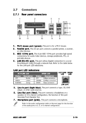
... connection 100Mbps connection 1Gbps connection ACT/LINK SPEED LED LED LAN port 5 . 2.7 Connectors 2.7.1 Rear panel connectors 1 2 3 4 5 6 7 12 11 10 9 8 1 . L A N ( R J - 4 5 ) p o r t . Refer to the audio configuration table on the next page for audio/video devices, storage peripherals, PCs, or portable devices. 4 . I n p o r t ( l i g h t b l u e ) . This 6-pin IEEE 1394a port provides high-speed connectivity for the function of this port becomes Front Speaker Out. 7 . This port connects a headphone or a speaker. ASUS A8R-MVP 2-19 This 25-pin port connects...
... connection 100Mbps connection 1Gbps connection ACT/LINK SPEED LED LED LAN port 5 . 2.7 Connectors 2.7.1 Rear panel connectors 1 2 3 4 5 6 7 12 11 10 9 8 1 . L A N ( R J - 4 5 ) p o r t . Refer to the audio configuration table on the next page for audio/video devices, storage peripherals, PCs, or portable devices. 4 . I n p o r t ( l i g h t b l u e ) . This 6-pin IEEE 1394a port provides high-speed connectivity for the function of this port becomes Front Speaker Out. 7 . This port connects a headphone or a speaker. ASUS A8R-MVP 2-19 This 25-pin port connects...
A8R-MVP User's Manual for English Edtion
Page 45
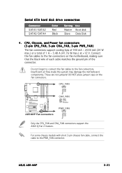
... Rotation +12V GND A8R-MVP ® A8R-MVP Fan connectors CHA_FAN GND +12V Rotation PWR_FAN Rotation +12V GND Only the CPU_FAN and CHA_FAN connectors support the ASUS Q-Fan 2 feature. ASUS A8R-MVP 2-23 Insufficient air flow inside the system may damage the motherboard components. These are not jumpers! Serial ATA hard disk drive connection Connector SATA1/SATA2 SATA3/SATA4 Color Red Black Setting Master Slave Use Boot disk Data Disk 4 . For some chassis models with short 3-pin chassis fan cable, connect the cable to the fan connectors.
... Rotation +12V GND A8R-MVP ® A8R-MVP Fan connectors CHA_FAN GND +12V Rotation PWR_FAN Rotation +12V GND Only the CPU_FAN and CHA_FAN connectors support the ASUS Q-Fan 2 feature. ASUS A8R-MVP 2-23 Insufficient air flow inside the system may damage the motherboard components. These are not jumpers! Serial ATA hard disk drive connection Connector SATA1/SATA2 SATA3/SATA4 Color Red Black Setting Master Slave Use Boot disk Data Disk 4 . For some chassis models with short 3-pin chassis fan cable, connect the cable to the fan connectors.

A8R-MVP User's Manual for English Edtion
Page 47
.... • The ATX 12 V Specification 2.0 compliant (400 W) PSU has been tested to support the below configuration: CPU: Memory: Graphics card: Hard disk: ATAPI: AMD FX-57 512 MB DDR (x4) PCI Express x16 ATI X850 SATA HD (x2) CD-ROM (x1) • Use of the system chassis. GAME/MIDI port connector (16-1 pin GAME) This connector is recommended when configuring a system with more power-consuming devices. Connect the USB/GAME module cable to this connector, then install the module...
.... • The ATX 12 V Specification 2.0 compliant (400 W) PSU has been tested to support the below configuration: CPU: Memory: Graphics card: Hard disk: ATAPI: AMD FX-57 512 MB DDR (x4) PCI Express x16 ATI X850 SATA HD (x2) CD-ROM (x1) • Use of the system chassis. GAME/MIDI port connector (16-1 pin GAME) This connector is recommended when configuring a system with more power-consuming devices. Connect the USB/GAME module cable to this connector, then install the module...
A8R-MVP User's Manual for English Edtion
Page 57
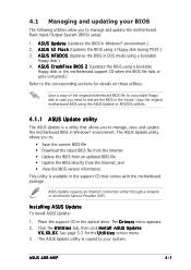
... drive. Installing ASUS Update To install ASUS Update: 1. Place the support CD in DOS mode using a bootable floppy disk or the motherboard support CD when the BIOS file fails or gets corrupted.) Refer to manage and update the motherboard Basic Input/Output System (BIOS) setup. 1. X X. ASUS A8R-MVP 4-1 Click the U t i l i t i e s tab, then click I O S 2 (Updates the BIOS using a bootable floppy disk.) 4. Save a copy of the original motherboard BIOS file to a bootable floppy disk in case you need to : • Save the current BIOS file • Download the latest BIOS...
... drive. Installing ASUS Update To install ASUS Update: 1. Place the support CD in DOS mode using a bootable floppy disk or the motherboard support CD when the BIOS file fails or gets corrupted.) Refer to manage and update the motherboard Basic Input/Output System (BIOS) setup. 1. X X. ASUS A8R-MVP 4-1 Click the U t i l i t i e s tab, then click I O S 2 (Updates the BIOS using a bootable floppy disk.) 4. Save a copy of the original motherboard BIOS file to a bootable floppy disk in case you need to : • Save the current BIOS file • Download the latest BIOS...
A8R-MVP User's Manual for English Edtion
Page 71
Main BIOS SETUP UTILITY Primary IDE Master Device : Hard Disk Vendor : ST320413A Size : 20.0GB LBA Mode : Supported Block Mode : 16 Sectors PIO Mode : 4 Async DMA : MultiWord DMA-2 Ultra DMA : Ultra DMA-6 SMART Monitoring: Supported Select the type of device connected to display the IDE device information. Change Option F1 General Help F10 Save and Exit ESC Exit v02.58 (C)Copyright 1985-2004, American Megatrends, Inc. Select [CDROM] if you are not user-configurable. Select a device item, then...
Main BIOS SETUP UTILITY Primary IDE Master Device : Hard Disk Vendor : ST320413A Size : 20.0GB LBA Mode : Supported Block Mode : 16 Sectors PIO Mode : 4 Async DMA : MultiWord DMA-2 Ultra DMA : Ultra DMA-6 SMART Monitoring: Supported Select the type of device connected to display the IDE device information. Change Option F1 General Help F10 Save and Exit ESC Exit v02.58 (C)Copyright 1985-2004, American Megatrends, Inc. Select [CDROM] if you are not user-configurable. Select a device item, then...
A8R-MVP User's Manual for English Edtion
Page 73
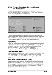
... specifications. Configuration options: [Emulated PATA Mode] [AHCI Mode] 4.3.6 System Information This menu gives you to configure Serial ATA RAID. Main BIOS SETUP UTILITY AMIBIOS Version : 0127 Build Date : 10/25/05 Processor Type : AMD Athlon (tm) 64 X2 Dual Core Processor Speed : 2400 MHz Count : 2 System Memory Size : 512 MB Select Screen Select Item F1 General Help F10 Save and Exit ESC Exit v02.58 (C)Copyright 1985-2004, American Megatrends, Inc. ASUS A8R-MVP 4-17 Onboard SATA Boot ROM [Disabled] Allows you to [Enabled]. Set...
... specifications. Configuration options: [Emulated PATA Mode] [AHCI Mode] 4.3.6 System Information This menu gives you to configure Serial ATA RAID. Main BIOS SETUP UTILITY AMIBIOS Version : 0127 Build Date : 10/25/05 Processor Type : AMD Athlon (tm) 64 X2 Dual Core Processor Speed : 2400 MHz Count : 2 System Memory Size : 512 MB Select Screen Select Item F1 General Help F10 Save and Exit ESC Exit v02.58 (C)Copyright 1985-2004, American Megatrends, Inc. ASUS A8R-MVP 4-17 Onboard SATA Boot ROM [Disabled] Allows you to [Enabled]. Set...

A8R-MVP User's Manual for English Edtion
Page 74
... 4: BIOS setup Main Advanced BIOS SETUP UTILITY Power Boot Exit Jumperfree Configuration CPU Configuration Chipset Onboard Devices Configuration PCI PnP LAN Cable Status USB Configuration Select Screen Select Item Enter Go to Sub Screen F1 General Help F10 Save and Exit ESC Exit v02.58 (C)Copyright 1985-2004, American Megatrends, Inc. 4.4.1 JumperFree Configuration Advanced BIOS SETUP UTILITY Configure System Frequency/Voltage AI Overclocking PCIE Frequency [Auto] [100] FID/VID Change DDR Voltage PCI-Express Voltage VCORE Over Voltage Southbridge Over-voltage [Auto] [Auto...
... 4: BIOS setup Main Advanced BIOS SETUP UTILITY Power Boot Exit Jumperfree Configuration CPU Configuration Chipset Onboard Devices Configuration PCI PnP LAN Cable Status USB Configuration Select Screen Select Item Enter Go to Sub Screen F1 General Help F10 Save and Exit ESC Exit v02.58 (C)Copyright 1985-2004, American Megatrends, Inc. 4.4.1 JumperFree Configuration Advanced BIOS SETUP UTILITY Configure System Frequency/Voltage AI Overclocking PCIE Frequency [Auto] [100] FID/VID Change DDR Voltage PCI-Express Voltage VCORE Over Voltage Southbridge Over-voltage [Auto] [Auto...
A8R-MVP User's Manual for English Edtion
Page 82
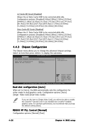
...] [20.97ms] [42.00ms] [84.00ms] Data Cache BG Scrub [Disabled] Allows the L1 Data Cache RAM to be able to change the advanced chipset settings. Advanced BIOS SETUP UTILITY ATI RD480 Chipset Configuration Dual-slot configuration RD800 HT PLL Control [Auto] [Normal] Dual-slot configuration. L2 Cache BG Scrub [Disabled] Allows the L2 Data Cache RAM to display the sub-menu. Change Option F1 General Help F10 Save and Exit ESC Exit v02...
...] [20.97ms] [42.00ms] [84.00ms] Data Cache BG Scrub [Disabled] Allows the L1 Data Cache RAM to be able to change the advanced chipset settings. Advanced BIOS SETUP UTILITY ATI RD480 Chipset Configuration Dual-slot configuration RD800 HT PLL Control [Auto] [Normal] Dual-slot configuration. L2 Cache BG Scrub [Disabled] Allows the L2 Data Cache RAM to display the sub-menu. Change Option F1 General Help F10 Save and Exit ESC Exit v02...
A8R-MVP User's Manual for English Edtion
Page 86
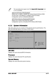
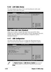
...Check LAN Cable [Disabled] Allows you to enable or disable LAN cable check during POST. Advanced BIOS SETUP UTILITY USB Configuration Module Version - 2.24.0-10.4 USB Devices Enabled: None USB Controller Legacy USB Support USB 2.0 Controller Mode BIOS EHCI Hand-off [USB1.1+2.0] [Auto] [HiSpeed] [Enabled] USB Mass Storage Device Configuration Select Screen Select Item +- 4.4.6 LAN Cable Status This menu displays the status of the Local Area Network (LAN) cable connected to display the configuration options. When enabled, the menu reports the cable faults or shorts, and displays the...
...Check LAN Cable [Disabled] Allows you to enable or disable LAN cable check during POST. Advanced BIOS SETUP UTILITY USB Configuration Module Version - 2.24.0-10.4 USB Devices Enabled: None USB Controller Legacy USB Support USB 2.0 Controller Mode BIOS EHCI Hand-off [USB1.1+2.0] [Auto] [HiSpeed] [Enabled] USB Mass Storage Device Configuration Select Screen Select Item +- 4.4.6 LAN Cable Status This menu displays the status of the Local Area Network (LAN) cable connected to display the configuration options. When enabled, the menu reports the cable faults or shorts, and displays the...
A8R-MVP User's Manual for English Edtion
Page 88
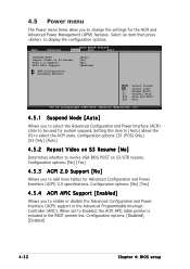
... in the Advanced Programmable Interrupt Controller (APIC). 4.5 Power menu The Power menu items allow you to add more tables for Advanced Configuration and Power Interface (ACPI) 2.0 specifications. Configuration options: [No] [Yes] 4.5.3 ACPI 2.0 Support [No] Allows you to select the ACPI state. Setting this item to [Auto] allows the OS to change the settings for the ACPI and Advanced Power Management (APM) features. Main Advanced BIOS SETUP UTILITY Power Boot Exit Suspend Mode Repost Video on S3/STR resume.
... in the Advanced Programmable Interrupt Controller (APIC). 4.5 Power menu The Power menu items allow you to add more tables for Advanced Configuration and Power Interface (ACPI) 2.0 specifications. Configuration options: [No] [Yes] 4.5.3 ACPI 2.0 Support [No] Allows you to select the ACPI state. Setting this item to [Auto] allows the OS to change the settings for the ACPI and Advanced Power Management (APM) features. Main Advanced BIOS SETUP UTILITY Power Boot Exit Suspend Mode Repost Video on S3/STR resume.
A8R-MVP User's Manual for English Edtion
Page 96
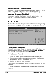
...19 Capture [Disabled] When set your password. again to display the configuration options. Configuration options: [Disabled] [Enabled] 4.6.3 Security The Security menu items allow you to change password. From the password box, type a password composed of the screen shows the default N o t I n s t a l l e d. Confirm the password when prompted. Select the Change Supervisor Password item and press . 2. After you successfully set to run Setup" during POST. Hit 'DEL' Message Display [Enabled] When set a Supervisor Password: 1. Select Screen Select Item Enter Change F1...
...19 Capture [Disabled] When set your password. again to display the configuration options. Configuration options: [Disabled] [Enabled] 4.6.3 Security The Security menu items allow you to change password. From the password box, type a password composed of the screen shows the default N o t I n s t a l l e d. Confirm the password when prompted. Select the Change Supervisor Password item and press . 2. After you successfully set to run Setup" during POST. Hit 'DEL' Message Display [Enabled] When set a Supervisor Password: 1. Select Screen Select Item Enter Change F1...
A8R-MVP User's Manual for English Edtion
Page 127
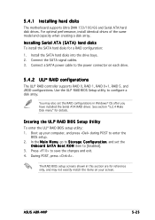
... to enter the BIOS setup. 2. The RAID BIOS setup screens shown in Windows® OS after you have installed the Serial ATA RAID driver. Connect the SATA signal cables. 3. Entering the ULI® RAID BIOS Setup Utility To enter the ULI® RAID BIOS setup utility: 1. For optimal performance, install identical drives of the same model and capacity when creating a disk array. You may not exactly match the items on each drive. 5.4.2 ULI® RAID configurations The ULI® RAID controller supports RAID 0, RAID 1, RAID 0+1, RAID 5, and JBOD configurations. ASUS A8R-MVP 5-25...
... to enter the BIOS setup. 2. The RAID BIOS setup screens shown in Windows® OS after you have installed the Serial ATA RAID driver. Connect the SATA signal cables. 3. Entering the ULI® RAID BIOS Setup Utility To enter the ULI® RAID BIOS setup utility: 1. For optimal performance, install identical drives of the same model and capacity when creating a disk array. You may not exactly match the items on each drive. 5.4.2 ULI® RAID configurations The ULI® RAID controller supports RAID 0, RAID 1, RAID 0+1, RAID 5, and JBOD configurations. ASUS A8R-MVP 5-25...
A8R-MVP User's Manual for English Edtion
Page 135
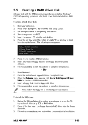
... enter the BIOS setup utility. 3. When the D r i v e r s menu appears, click M a k e U L i C h i p s e t D r i v e r D i s k to complete the process. Place the motherboard support CD into the optical drive. 6. Follow succeeding screen instructions to create a ULI RAID driver disk. 4. ASUS A8R-MVP 5-33 Press the any key when the system prompts "Press any key to create a RAID driver disk. 8. Insert a formatted floppy disk into the floppy disk drive. 5. To install the RAID driver: 1. OR 1. Insert a floppy disk into the floppy drive then press . 9. Press to boot...
... enter the BIOS setup utility. 3. When the D r i v e r s menu appears, click M a k e U L i C h i p s e t D r i v e r D i s k to complete the process. Place the motherboard support CD into the optical drive. 6. Follow succeeding screen instructions to create a ULI RAID driver disk. 4. ASUS A8R-MVP 5-33 Press the any key when the system prompts "Press any key to create a RAID driver disk. 8. Insert a formatted floppy disk into the floppy disk drive. 5. To install the RAID driver: 1. OR 1. Insert a floppy disk into the floppy drive then press . 9. Press to boot...


