A8N-VM User's Manual for English Edtion
Page 1
A8N-VM Motherboard
A8N-VM Motherboard
A8N-VM User's Manual for English Edtion
Page 3
Contents Notices vi Safety information vii A8N-VM specifications summary viii Chapter 1: Product introduction 1.1 Welcome 1-2 1.2 Package contents 1-2 1.3 Special features 1-2 1.3.1 Product highlights 1-2 1.3.2 Innovative ASUS features 1-4 1.4 Before you proceed 1-5 1.5 Motherboard overview 1-6 1.5.1 Motherboard layout 1-6 1.5.2 Placement direction 1-7 1.5.3 Screw holes 1-7 1.6 Central Processing Unit (CPU 1-8 1.7 System memory 1-10 1.7.1 Overview 10 1.7.2 Memory configurations 1-10 1.7.3 Installing a DIMM 1-12 1.7.4 Removing a DIMM 1-12 1.8 Expansion slots 1-...
Contents Notices vi Safety information vii A8N-VM specifications summary viii Chapter 1: Product introduction 1.1 Welcome 1-2 1.2 Package contents 1-2 1.3 Special features 1-2 1.3.1 Product highlights 1-2 1.3.2 Innovative ASUS features 1-4 1.4 Before you proceed 1-5 1.5 Motherboard overview 1-6 1.5.1 Motherboard layout 1-6 1.5.2 Placement direction 1-7 1.5.3 Screw holes 1-7 1.6 Central Processing Unit (CPU 1-8 1.7 System memory 1-10 1.7.1 Overview 10 1.7.2 Memory configurations 1-10 1.7.3 Installing a DIMM 1-12 1.7.4 Removing a DIMM 1-12 1.8 Expansion slots 1-...
A8N-VM User's Manual for English Edtion
Page 7
...• Avoid dust, humidity, and temperature extremes. Contact a qualified service technician or your area. Operation safety • Before installing the motherboard and adding devices on it, carefully read all power cables are not sure about the voltage of the electrical outlet you detect any area where... product, contact a qualified service technician or your retailer. If you are using the product, make sure all power cables from the motherboard, ensure that all the manuals that your power supply is broken, do not try to the correct voltage in any damage, contact...
...• Avoid dust, humidity, and temperature extremes. Contact a qualified service technician or your area. Operation safety • Before installing the motherboard and adding devices on it, carefully read all power cables are not sure about the voltage of the electrical outlet you detect any area where... product, contact a qualified service technician or your retailer. If you are using the product, make sure all power cables from the motherboard, ensure that all the manuals that your power supply is broken, do not try to the correct voltage in any damage, contact...
A8N-VM User's Manual for English Edtion
Page 11
This chapter describes the motherboard features and the new technologies it supports. 1Product introduction
This chapter describes the motherboard features and the new technologies it supports. 1Product introduction
A8N-VM User's Manual for English Edtion
Page 12
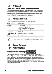
... a powerful platform for your retailer. 1.3 Special features 1.3.1 Product highlights Latest processor technology The motherboard comes with the list below. 1.2 Package contents Check your motherboard package for buying an ASUS® A8N-VM motherboard! Before you for the following items. Motherboard Cables Accessory Application CD Documentation ASUS A8N-VM motherboard 1 x Serial ATA signal cable 1 x Serial ATA power cable 1 x Ultra DMA 133/100...
... a powerful platform for your retailer. 1.3 Special features 1.3.1 Product highlights Latest processor technology The motherboard comes with the list below. 1.2 Package contents Check your motherboard package for buying an ASUS® A8N-VM motherboard! Before you for the following items. Motherboard Cables Accessory Application CD Documentation ASUS A8N-VM motherboard 1 x Serial ATA signal cable 1 x Serial ATA power cable 1 x Ultra DMA 133/100...
A8N-VM User's Manual for English Edtion
Page 13
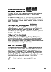
...Express features point-to-point serial interconnections between devices and allows higher clockspeeds by carrying data in RAID mode. ASUS A8N-VM 1-3 Serial ATA II technology The motherboard supports the Serial ATA 3 Gb/s technology through the Serial ATA interfaces and the NVIDIA® nForce™...Swap function is software compatible with existing PCI specifications. See page 1-10 for Serial ATA II. PCI Express™ interface The motherboard fully supports PCI Express, the latest I/O interconnect technology that speeds up to4 GB of new features, including Native Command Queueing ...
...Express features point-to-point serial interconnections between devices and allows higher clockspeeds by carrying data in RAID mode. ASUS A8N-VM 1-3 Serial ATA II technology The motherboard supports the Serial ATA 3 Gb/s technology through the Serial ATA interfaces and the NVIDIA® nForce™...Swap function is software compatible with existing PCI specifications. See page 1-10 for Serial ATA II. PCI Express™ interface The motherboard fully supports PCI Express, the latest I/O interconnect technology that speeds up to4 GB of new features, including Native Command Queueing ...

A8N-VM User's Manual for English Edtion
Page 14
... Flash BIOS With the ASUS EZ Flash, you can easily update the system BIOS even before loading the operating system. This protection eliminates the need to buy a replacement ROM chip. USB 2.0 technology The motherboard implements the Universal Serial Bus (USB) 2.0 specification, dramatically increasing the ...system hangs due to overclocking. USB 2.0 is backward compatible with customizable boot logos. See page 2-35 for details. feature of the motherboard BIOS allows automatic re-setting to the BIOS default settings in case when the BIOS codes and data are corrupted. The S/PDIF ...
... Flash BIOS With the ASUS EZ Flash, you can easily update the system BIOS even before loading the operating system. This protection eliminates the need to buy a replacement ROM chip. USB 2.0 technology The motherboard implements the Universal Serial Bus (USB) 2.0 specification, dramatically increasing the ...system hangs due to overclocking. USB 2.0 is backward compatible with customizable boot logos. See page 2-35 for details. feature of the motherboard BIOS allows automatic re-setting to the BIOS default settings in case when the BIOS codes and data are corrupted. The S/PDIF ...
A8N-VM User's Manual for English Edtion
Page 15
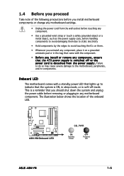
... handling components to avoid damaging them due to static electricity • Hold components by the edges to the motherboard, peripherals, and/or components. A8N-VM ® A8N-VM Onboard LED SB_PWR ON Standby Power OFF Powered Off ASUS A8N-VM 1-5 1.4 Before you proceed Take note of the onboard LED. The illustration below shows the location of the following...
... handling components to avoid damaging them due to static electricity • Hold components by the edges to the motherboard, peripherals, and/or components. A8N-VM ® A8N-VM Onboard LED SB_PWR ON Standby Power OFF Powered Off ASUS A8N-VM 1-5 1.4 Before you proceed Take note of the onboard LED. The illustration below shows the location of the following...
A8N-VM User's Manual for English Edtion
Page 17
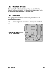
Place this side towards the rear of the chassis as indicated in the image below. 1.5.3 Screw holes Place eight (8) screws into the chassis in the correct orientation. The edge with external ports goes to the rear part of the chassis ® A8N-VM ASUS A8N-VM 1-7 Do not overtighten the screws! Doing so can damage the motherboard. 1.5.2 Placement direction When installing the motherboard, make sure that you place it into the holes indicated by circles to secure the motherboard to the chassis.
Place this side towards the rear of the chassis as indicated in the image below. 1.5.3 Screw holes Place eight (8) screws into the chassis in the correct orientation. The edge with external ports goes to the rear part of the chassis ® A8N-VM ASUS A8N-VM 1-7 Do not overtighten the screws! Doing so can damage the motherboard. 1.5.2 Placement direction When installing the motherboard, make sure that you place it into the holes indicated by circles to secure the motherboard to the chassis.
A8N-VM User's Manual for English Edtion
Page 18
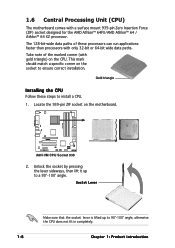
1.6 Central Processing Unit (CPU) The motherboard comes with only 32-bit or 64-bit wide data paths. Locate the 939-pin ZIF socket...Zero Insertion Force (ZIF) socket designed for the AMD Athlon™ 64FX/AMD Athlon™ 64 / Athlon™ 64 X2 processor. A8N-VM ® A8N-VM CPU Socket 939 2. Socket Lever Make sure that the socket lever is lifted up to install a CPU. 1. This mark should match a... Chapter 1: Product introduction The 128-bit-wide data paths of the marked corner (with gold triangle) on the motherboard. Take note of these steps to a 90°-100° angle.
1.6 Central Processing Unit (CPU) The motherboard comes with only 32-bit or 64-bit wide data paths. Locate the 939-pin ZIF socket...Zero Insertion Force (ZIF) socket designed for the AMD Athlon™ 64FX/AMD Athlon™ 64 / Athlon™ 64 X2 processor. A8N-VM ® A8N-VM CPU Socket 939 2. Socket Lever Make sure that the socket lever is lifted up to install a CPU. 1. This mark should match a... Chapter 1: Product introduction The 128-bit-wide data paths of the marked corner (with gold triangle) on the motherboard. Take note of these steps to a 90°-100° angle.
A8N-VM User's Manual for English Edtion
Page 19
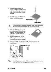
...CPU into the socket to prevent bending the pins and damaging the CPU! 5. Small triangle Gold triangle The CPU fits only in place. ASUS A8N-VM 1-9 Connect the CPU fan cable to the CPU_FAN connector on the side tab to secure the CPU. DO NOT force the CPU into the... the socket corner with the heatsink package. 7. CPU_FAN A8N-VM GND +12V Rotation ® A8N-VM CPU fan connector Do not forget to plug this connector. When the CPU is locked. 6. Position the CPU above the socket such that it fits in one correct orientation. 3. The lever clicks on the motherboard.
...CPU into the socket to prevent bending the pins and damaging the CPU! 5. Small triangle Gold triangle The CPU fits only in place. ASUS A8N-VM 1-9 Connect the CPU fan cable to the CPU_FAN connector on the side tab to secure the CPU. DO NOT force the CPU into the... the socket corner with the heatsink package. 7. CPU_FAN A8N-VM GND +12V Rotation ® A8N-VM CPU fan connector Do not forget to plug this connector. When the CPU is locked. 6. Position the CPU above the socket such that it fits in one correct orientation. 3. The lever clicks on the motherboard.
A8N-VM User's Manual for English Edtion
Page 20
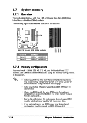
1.7 System memory 1.7.1 Overview The motherboard comes with less than or equal to chipset limitation, this section. • Installing DDR DIMMs other than the recommended configurations may cause memory sizing error or system boot failure. Use any of the sockets: A8N-VM DIMM_A2 DIMM_A1 DIMM_B2 DIMM_B1 ® A8N-VM 184-pin DDR DIMM sockets Channel Channel 1 Channel...
1.7 System memory 1.7.1 Overview The motherboard comes with less than or equal to chipset limitation, this section. • Installing DDR DIMMs other than the recommended configurations may cause memory sizing error or system boot failure. Use any of the sockets: A8N-VM DIMM_A2 DIMM_A1 DIMM_B2 DIMM_B1 ® A8N-VM 184-pin DDR DIMM sockets Channel Channel 1 Channel...
A8N-VM User's Manual for English Edtion
Page 21
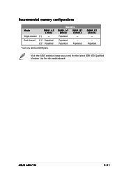
Recommended memory configurations Mode Single-channel DIMM_A2 (blue) (1)* - Sockets DIMM_A1 (blue) DIMM_B2 (black) Populated - Dual-channel (1)* Populated (2)* Populated * Use only identical DIMM pairs. Populated Visit the ASUS website (www.asus.com) for the latest DDR 400 Qualified Vendors List for this motherboard. Populated Populated - ASUS A8N-VM 1-11 Populated DIMM_B1 (black) - -
Recommended memory configurations Mode Single-channel DIMM_A2 (blue) (1)* - Sockets DIMM_A1 (blue) DIMM_B2 (black) Populated - Dual-channel (1)* Populated (2)* Populated * Use only identical DIMM pairs. Populated Visit the ASUS website (www.asus.com) for the latest DDR 400 Qualified Vendors List for this motherboard. Populated Populated - ASUS A8N-VM 1-11 Populated DIMM_B1 (black) - -
A8N-VM User's Manual for English Edtion
Page 22
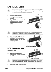
.... 1 2 DDR DIMM notch 1 A DDR DIMM is properly seated. 1.7.4 Removing a DIMM To remove a DIMM: Locked Retaining Clip 2 1. Simultaneously press the retaining clips outward to both the motherboard and the components. 1. 1.7.3 Installing a DIMM Make sure to avoid damaging the DIMM. 3. DO NOT force a DIMM into the socket until the retaining clips snap back...
.... 1 2 DDR DIMM notch 1 A DDR DIMM is properly seated. 1.7.4 Removing a DIMM To remove a DIMM: Locked Retaining Clip 2 1. Simultaneously press the retaining clips outward to both the motherboard and the components. 1. 1.7.3 Installing a DIMM Make sure to avoid damaging the DIMM. 3. DO NOT force a DIMM into the socket until the retaining clips snap back...
A8N-VM User's Manual for English Edtion
Page 23
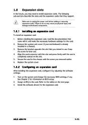
...Refer to unplug the power cord before adding or removing expansion cards. 1.8 Expansion slots In the future, you physical injury and damage motherboard components. 1.8.1 Installing an expansion card To install an expansion card: 1. The following sub-sections describe the slots and the expansion cards...the software drivers for information on the system and change the necessary BIOS settings, if any. Keep the screw for the card. 2. ASUS A8N-VM 1-13 Turn on BIOS setup. 2. Remove the bracket opposite the slot that they support. Before installing the expansion card, read the ...
...Refer to unplug the power cord before adding or removing expansion cards. 1.8 Expansion slots In the future, you physical injury and damage motherboard components. 1.8.1 Installing an expansion card To install an expansion card: 1. The following sub-sections describe the slots and the expansion cards...the software drivers for information on the system and change the necessary BIOS settings, if any. Keep the screw for the card. 2. ASUS A8N-VM 1-13 Turn on BIOS setup. 2. Remove the bracket opposite the slot that they support. Before installing the expansion card, read the ...
A8N-VM User's Manual for English Edtion
Page 24
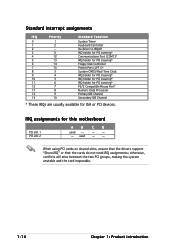
...* IRQ holder for PCI steering* PS/2 Compatible Mouse Port* Numeric Data Processor Primary IDE Channel Secondary IDE Channel * These IRQs are usually available for this motherboard PCI slot 1 PCI slot 2 A B C D used - -
...* IRQ holder for PCI steering* PS/2 Compatible Mouse Port* Numeric Data Processor Primary IDE Channel Secondary IDE Channel * These IRQs are usually available for this motherboard PCI slot 1 PCI slot 2 A B C D used - -
A8N-VM User's Manual for English Edtion
Page 25
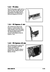
The figure shows a LAN card installed on a PCI slot. 1.8.4 PCI Express x1 slot This motherboard supports PCI Express x1 network cards, SCSI cards and other cards that comply with the PCI Express specifications. ASUS A8N-VM 1-15 The following figure shows a network card installed on the PCI Express x16 slot. 1.8.3 PCI slots The PCI ... cards that comply with PCI Express specifications. The figure shows a graphics card installed on the PCI Express x1 slot. 1.8.5 PCI Express x16 slot This motherboard has supports PCI Express x16 graphic cards that comply with PCI specifications.
The figure shows a LAN card installed on a PCI slot. 1.8.4 PCI Express x1 slot This motherboard supports PCI Express x1 network cards, SCSI cards and other cards that comply with the PCI Express specifications. ASUS A8N-VM 1-15 The following figure shows a network card installed on the PCI Express x16 slot. 1.8.3 PCI slots The PCI ... cards that comply with PCI Express specifications. The figure shows a graphics card installed on the PCI Express x1 slot. 1.8.5 PCI Express x16 slot This motherboard has supports PCI Express x16 graphic cards that comply with PCI specifications.
A8N-VM User's Manual for English Edtion
Page 32
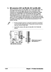
...-1 pin SEC_IDE) These connectors are for Ultra DMA 133/100/66 IDE devices. A8N-VM SEC_IDE PRI_IDE ® A8N-VM IDE connectors PIN 1 NOTE: Orient the red markings (usually zigzag) on the IDE ribbon cable to match the covered hole on the motherboard, a black connector for an Ultra DMA 133/100/66 IDE slave device...
...-1 pin SEC_IDE) These connectors are for Ultra DMA 133/100/66 IDE devices. A8N-VM SEC_IDE PRI_IDE ® A8N-VM IDE connectors PIN 1 NOTE: Orient the red markings (usually zigzag) on the IDE ribbon cable to match the covered hole on the motherboard, a black connector for an Ultra DMA 133/100/66 IDE slave device...
A8N-VM User's Manual for English Edtion
Page 34
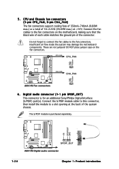
...88W max.) or a total of the system chassis. These are not jumpers! CPU_FAN CPU_FAN CHA_FAN CHA_FAN ® A8N-VM Fan connectors 6 . GND +12V Rotation A8N-VM +5V SPDIFOUT GND ® SPDIF_OUT A8N-VM Digital audio connector 1-24 Chapter 1: Product introduction Do not forget to connect the fan cables to the fan connectors...back of 1A~2.22A (26.64W max.) at +12V. Insufficient air flow inside the system may damage the motherboard components. DO NOT place jumper caps on the motherboard, making sure that the black wire of each cable matches the ground pin of the connector. Connect the fan...
...88W max.) or a total of the system chassis. These are not jumpers! CPU_FAN CPU_FAN CHA_FAN CHA_FAN ® A8N-VM Fan connectors 6 . GND +12V Rotation A8N-VM +5V SPDIFOUT GND ® SPDIF_OUT A8N-VM Digital audio connector 1-24 Chapter 1: Product introduction Do not forget to connect the fan cables to the fan connectors...back of 1A~2.22A (26.64W max.) at +12V. Insufficient air flow inside the system may damage the motherboard components. DO NOT place jumper caps on the motherboard, making sure that the black wire of each cable matches the ground pin of the connector. Connect the fan...
A8N-VM User's Manual for English Edtion
Page 36
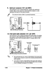
... Legacy AC'97-compliant pin definition GND PRESENCE# SENSE1_RETUR SENSE2_RETUR A8N-VM AGND NC NC NC ® AAFP MIC2_L MIC2_R Line out_R NC Line out_L PORT1 L PORT1 R PORT2 R SENSE_SEND PORT2 L A8N-VM Analog front panel connector • We recommend that you want...A8N-VM COM1 PIN 1 ® A8N-VM COM port connector 10. Front panel audio connector (10-1 pin AAFP) This connector is set to avail of the system chassis. See page 2-27 for a chassis-mounted front panel audio I /O module cable to this connector, then install the module to a slot opening at the back of the motherboard...
... Legacy AC'97-compliant pin definition GND PRESENCE# SENSE1_RETUR SENSE2_RETUR A8N-VM AGND NC NC NC ® AAFP MIC2_L MIC2_R Line out_R NC Line out_L PORT1 L PORT1 R PORT2 R SENSE_SEND PORT2 L A8N-VM Analog front panel connector • We recommend that you want...A8N-VM COM1 PIN 1 ® A8N-VM COM port connector 10. Front panel audio connector (10-1 pin AAFP) This connector is set to avail of the system chassis. See page 2-27 for a chassis-mounted front panel audio I /O module cable to this connector, then install the module to a slot opening at the back of the motherboard...


