
Motherboard DIY Troubleshooting Guide
Page 31
01 01 01 ASUS MR-1 Unlike that of standard cards, the component side of the specially-designed AMR card faces the motherboard's expansion slots when the card is installed A7V133 A7V133 Audio Modem Riser (AMR) Slot 31
01 01 01 ASUS MR-1 Unlike that of standard cards, the component side of the specially-designed AMR card faces the motherboard's expansion slots when the card is installed A7V133 A7V133 Audio Modem Riser (AMR) Slot 31

A7V133 User Manual
Page 1
® A7V133 A7V133-C JumperFree™ PC133/VC133 200/266MHz FSB AGP Pro/4X Socket A Motherboard USER'S MANUAL A7V133: INCLUDES Promise IDE ATA-100/RAID 0/1 chip A7V133-C: DOES NOT INCLUDE Promise IDE ATA-100/RAID 0/1 chip
® A7V133 A7V133-C JumperFree™ PC133/VC133 200/266MHz FSB AGP Pro/4X Socket A Motherboard USER'S MANUAL A7V133: INCLUDES Promise IDE ATA-100/RAID 0/1 chip A7V133-C: DOES NOT INCLUDE Promise IDE ATA-100/RAID 0/1 chip

A7V133 User Manual
Page 4
... 4.1.2 Updating BIOS Procedures 48 4.2 BIOS Setup Program 50 4.2.1 BIOS Menu Bar 51 4.2.2 Legend Bar 52 4.3 Main Menu 54 4 ASUS A7V133 User's Manual HARDWARE SETUP 14 3.1 Motherboard Layout 14 3.2 Layout Contents 15 3.3 Hardware Setup Procedure 17 3.4 Motherboard Settings 17 3.5 System Memory (DIMM 25 3.5.1 General DIMM Notes 25 3.5.2 Memory Installation 26 3.6 Central Processing Unit (CPU 27...
... 4.1.2 Updating BIOS Procedures 48 4.2 BIOS Setup Program 50 4.2.1 BIOS Menu Bar 51 4.2.2 Legend Bar 52 4.3 Main Menu 54 4 ASUS A7V133 User's Manual HARDWARE SETUP 14 3.1 Motherboard Layout 14 3.2 Layout Contents 15 3.3 Hardware Setup Procedure 17 3.4 Motherboard Settings 17 3.5 System Memory (DIMM 25 3.5.1 General DIMM Notes 25 3.5.2 Memory Installation 26 3.6 Central Processing Unit (CPU 27...

A7V133 User Manual
Page 5
APPENDIX 103 7.1 PCI-L101 Fast Ethernet Card 103 7.2 Modem Riser 105 7.3 Glossary 107 ASUS A7V133 User's Manual 5 SOFTWARE REFERENCE 94 6.1 ASUS PC Probe 94 6.2 CyberLink PowerPlayer SE 99 6.3 CyberLink PowerDVD 100 6.4 CyberLink VideoLive Mail 101 7. CONTENTS 4.3.1 ... Hardware Monitor 78 4.6 Boot Menu 79 4.7 Exit Menu 81 5. SOFTWARE SETUP 83 5.1 Install Operating System 83 5.2 Start Windows 83 5.3 A7V133 Series Motherboard Support CD 84 5.4 Using the Promise® Chip for RAID 0 and 1 86 5.4.1 Installing the Hard Disks 87 5.4.2 Enter FastTrak100 BIOS ...
APPENDIX 103 7.1 PCI-L101 Fast Ethernet Card 103 7.2 Modem Riser 105 7.3 Glossary 107 ASUS A7V133 User's Manual 5 SOFTWARE REFERENCE 94 6.1 ASUS PC Probe 94 6.2 CyberLink PowerPlayer SE 99 6.3 CyberLink PowerDVD 100 6.4 CyberLink VideoLive Mail 101 7. CONTENTS 4.3.1 ... Hardware Monitor 78 4.6 Boot Menu 79 4.7 Exit Menu 81 5. SOFTWARE SETUP 83 5.1 Install Operating System 83 5.2 Start Windows 83 5.3 A7V133 Series Motherboard Support CD 84 5.4 Using the Promise® Chip for RAID 0 and 1 86 5.4.1 Installing the Hard Disks 87 5.4.2 Enter FastTrak100 BIOS ...

A7V133 User Manual
Page 7
... (1) ASUS Support CD with UltraDMA/33 IDE drives/devices) (1) Ribbon cable for the included software Optional items and general reference 1.2 Item Checklist Check that your retailer. INTRODUCTION 2. 1. Package Contents (1) ASUS Motherboard (2) 40-pin 80-conductor ribbon cable for internal UltraDMA/ 100 / UltraDMA/66 (also compatible with drivers and utilities (1) This Motherboard User's Manual ASUS A7V133 User...
... (1) ASUS Support CD with UltraDMA/33 IDE drives/devices) (1) Ribbon cable for the included software Optional items and general reference 1.2 Item Checklist Check that your retailer. INTRODUCTION 2. 1. Package Contents (1) ASUS Motherboard (2) 40-pin 80-conductor ribbon cable for internal UltraDMA/ 100 / UltraDMA/66 (also compatible with drivers and utilities (1) This Motherboard User's Manual ASUS A7V133 User...

A7V133 User Manual
Page 8
...data to 1.5GB of frequency and Vcore voltage all through BIOS setup when JumperFree™ mode is enabled. 2. FEATURES 2.1 The ASUS A7V133 / A7V133-C The ASUS A7V133 motherboard is optimized to 1.5GB. up to deliver enhanced AMD Athlon™/Duron™ processor system performance. • "Super South" ... 16, 32, 64, 128, 256, or 512MB) or NEC's VC133-compliant Virtual Channel (VC) SDRAM up to each other. 8 ASUS A7V133 User's Manual VC SDRAM is a new DRAM core architecture that dramatically improves the memory system's ability to service, among others, high multimedia requirements...
...data to 1.5GB of frequency and Vcore voltage all through BIOS setup when JumperFree™ mode is enabled. 2. FEATURES 2.1 The ASUS A7V133 / A7V133-C The ASUS A7V133 motherboard is optimized to 1.5GB. up to deliver enhanced AMD Athlon™/Duron™ processor system performance. • "Super South" ... 16, 32, 64, 128, 256, or 512MB) or NEC's VC133-compliant Virtual Channel (VC) SDRAM up to each other. 8 ASUS A7V133 User's Manual VC SDRAM is a new DRAM core architecture that dramatically improves the memory system's ability to service, among others, high multimedia requirements...

A7V133 User Manual
Page 9
...external peripherals, personal gadgets, or an optional remote controller. • Desktop Management Interface (DMI): Supports DMI through an optional ASUS PCI-L101 10/100 Fast Ethernet PCI card (see 7. FEATURES • UltraDMA/100 Support: Comes with an onboard PCI... Anti-Boot Virus Protection: Programmable BIOS (Flash EEPROM), offering enhanced ACPI for Windows 98 compatibility, built-in this motherboard are color-coded. FEA TURES Specifications 2. ASUS A7V133 User's Manual 9 Power supply is used to physically transport commands and information between SMBus devices. • PCI...
...external peripherals, personal gadgets, or an optional remote controller. • Desktop Management Interface (DMI): Supports DMI through an optional ASUS PCI-L101 10/100 Fast Ethernet PCI card (see 7. FEATURES • UltraDMA/100 Support: Comes with an onboard PCI... Anti-Boot Virus Protection: Programmable BIOS (Flash EEPROM), offering enhanced ACPI for Windows 98 compatibility, built-in this motherboard are color-coded. FEA TURES Specifications 2. ASUS A7V133 User's Manual 9 Power supply is used to physically transport commands and information between SMBus devices. • PCI...

A7V133 User Manual
Page 10
... rate (1.064GB/s max using PC133-compliant SDRAMs and 800MB/s max using PC100-compliant SDRAMs). 10 ASUS A7V133 User's Manual The VCM's core design provides up to 50% higher SDRAM speed at reduced power consumption of this motherboard meet the stringent requirements for PC 99 certification The new PC 99 requirements for systems and...
... rate (1.064GB/s max using PC133-compliant SDRAMs and 800MB/s max using PC100-compliant SDRAMs). 10 ASUS A7V133 User's Manual The VCM's core design provides up to 50% higher SDRAM speed at reduced power consumption of this motherboard meet the stringent requirements for PC 99 certification The new PC 99 requirements for systems and...

A7V133 User Manual
Page 11
...ensure proper system configuration and management. • Chassis Intrusion Detection: Supports chassis-intrusion monitoring through an internal or external modem. ASUS A7V133 User's Manual 11 The system resource monitor will power off mode, depending on battery power for more critical for its normal RPM...Windows 98/2000/ ME/NT and OS/2, require much more memory and hard drive space to critical motherboard components. When the power button is monitored by the ASUS ASIC to prevent system overheat and system damage. • Voltage Monitoring and Alert: System voltage levels...
...ensure proper system configuration and management. • Chassis Intrusion Detection: Supports chassis-intrusion monitoring through an internal or external modem. ASUS A7V133 User's Manual 11 The system resource monitor will power off mode, depending on battery power for more critical for its normal RPM...Windows 98/2000/ ME/NT and OS/2, require much more memory and hard drive space to critical motherboard components. When the power button is monitored by the ASUS ASIC to prevent system overheat and system damage. • Voltage Monitoring and Alert: System voltage levels...

A7V133 User Manual
Page 12
... See opposite page for Socket A AMD Athlon/Duron Processors 3 (NOTE: the CPU thermal sensor is integrated on the motherboard, located near the center of the CPU heat source, just below the CPU socket) Feature Setting DIP Switches 6 Chipsets VIA VT8363A (VIA ...on audio model only) ... (Bottom) 23 Network Features Wake-On-LAN Connector 17 Wake-On-Ring Connector 13 Hardware Monitoring System Voltage Monitoring (integrated in ASUS ASIC) ....... 15 3 Fan Power and Speed Monitoring Connectors Power ATX Power Supply Connector 5 Special Feature Onboard LED 21 Promise® Ultra DMA/100 ...
... See opposite page for Socket A AMD Athlon/Duron Processors 3 (NOTE: the CPU thermal sensor is integrated on the motherboard, located near the center of the CPU heat source, just below the CPU socket) Feature Setting DIP Switches 6 Chipsets VIA VT8363A (VIA ...on audio model only) ... (Bottom) 23 Network Features Wake-On-LAN Connector 17 Wake-On-Ring Connector 13 Hardware Monitoring System Voltage Monitoring (integrated in ASUS ASIC) ....... 15 3 Fan Power and Speed Monitoring Connectors Power ATX Power Supply Connector 5 Special Feature Onboard LED 21 Promise® Ultra DMA/100 ...

A7V133 User Manual
Page 13
FEA TURES Motherboard Parts 2. 2. FEATURES 2.2.1 Component Locations 1 2 3 4 56 7 8 28 27 26 25 24 23 22 21 20 19 - 18 17 16 15 14 13 12 1110 9 ASUS A7V133 User's Manual 13
FEA TURES Motherboard Parts 2. 2. FEATURES 2.2.1 Component Locations 1 2 3 4 56 7 8 28 27 26 25 24 23 22 21 20 19 - 18 17 16 15 14 13 12 1110 9 ASUS A7V133 User's Manual 13

A7V133 User Manual
Page 14
... bit, 168-pin module) DIMM1 (64/72 bit, 168-pin module) ATX Power Connector PRIMARY IDE FLOPPY 30.6cm (12in) 3. HARDWARE SETUP 3.1 Motherboard Layout PS/2 T: Mouse B: Keyboard USB T: Port0 B: Port1 COM1 24.5cm (9.64in) JTPWR 01 01 01 PWR_FAN VIO 3VSBSLT CLRTC CR2032 3V Lithium ...3 PCI Slot 4 A7V133 WOLCON PCI Slot 5 Audio Modem Riser (AMR) WOR ASUS ASIC JEN AS99127F USBPORT CHASSIS JP13 JP14 IR IDELED PANEL Grayed components are optional at the time of purchase (JTCPU is no longer necessary on motherboards with PCB versions 1.02 and later) 14 ASUS A7V133 User's Manual H/W ...
... bit, 168-pin module) DIMM1 (64/72 bit, 168-pin module) ATX Power Connector PRIMARY IDE FLOPPY 30.6cm (12in) 3. HARDWARE SETUP 3.1 Motherboard Layout PS/2 T: Mouse B: Keyboard USB T: Port0 B: Port1 COM1 24.5cm (9.64in) JTPWR 01 01 01 PWR_FAN VIO 3VSBSLT CLRTC CR2032 3V Lithium ...3 PCI Slot 4 A7V133 WOLCON PCI Slot 5 Audio Modem Riser (AMR) WOR ASUS ASIC JEN AS99127F USBPORT CHASSIS JP13 JP14 IR IDELED PANEL Grayed components are optional at the time of purchase (JTCPU is no longer necessary on motherboards with PCB versions 1.02 and later) 14 ASUS A7V133 User's Manual H/W ...

A7V133 User Manual
Page 15
3. H/W SETUP Layout Contents Motherboard Settings 1) DSW p. 18 DIP Switches 2) JEN p. 18 JumperFree Mode (JumperFree/Jumper Mode) 3) AUDIOCODEC p. 19 Onboard Audio Setting (Enable/Enable) (optional) 4) 3VSBSLT p. 20 PCI 3Volt Setting (3 ...) PWR_, CPU_,CHA_FAN p. 39 Chassis, Power Supply, CPU, F_ Fan Connectors (3 pin) F_FAN 15) CD_IN, AUX p. 40 Internal Audio Connectors (Four 4-pin) (optional) MODEM continued... ASUS A7V133 User's Manual HARDWARE SETUP 3.2 Layout Contents 3.
3. H/W SETUP Layout Contents Motherboard Settings 1) DSW p. 18 DIP Switches 2) JEN p. 18 JumperFree Mode (JumperFree/Jumper Mode) 3) AUDIOCODEC p. 19 Onboard Audio Setting (Enable/Enable) (optional) 4) 3VSBSLT p. 20 PCI 3Volt Setting (3 ...) PWR_, CPU_,CHA_FAN p. 39 Chassis, Power Supply, CPU, F_ Fan Connectors (3 pin) F_FAN 15) CD_IN, AUX p. 40 Internal Audio Connectors (Four 4-pin) (optional) MODEM continued... ASUS A7V133 User's Manual HARDWARE SETUP 3.2 Layout Contents 3.
A7V133 User Manual
Page 17
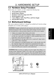
..., or other components. 4. Use a grounded wrist strap before you unplug your hands to a safely grounded object or to your motherboard's function settings through the use of your power supply when adding or removing system components. Install the Central Processing Unit (CPU) ... WARNING! Place components on a grounded antistatic pad or on the motherboard. Ensure that the system is switched off mode and not powered OFF. 01 01 01 A7V133 A7V133 Onboard LED ON Standby Power OFF Powered Off ASUS A7V133 User's Manual HARDWARE SETUP 3.3 Hardware Setup Procedure Before using your ...
..., or other components. 4. Use a grounded wrist strap before you unplug your hands to a safely grounded object or to your motherboard's function settings through the use of your power supply when adding or removing system components. Install the Central Processing Unit (CPU) ... WARNING! Place components on a grounded antistatic pad or on the motherboard. Ensure that the system is switched off mode and not powered OFF. 01 01 01 A7V133 A7V133 Onboard LED ON Standby Power OFF Powered Off ASUS A7V133 User's Manual HARDWARE SETUP 3.3 Hardware Setup Procedure Before using your ...

A7V133 User Manual
Page 18
... VID1 JEN 12 JEN 23 ASUS A7V133 User's Manual 3. The example below shows all the switches in the ON position. The default setting is OFF. The JumperFree™ mode allows processor settings to enable or disable the JumperFree™ mode. HARDWARE SETUP 1) Motherboard Features Settings (DIP Switches - H/W SETUP Motherboard Settings 01 01 01 01...
... VID1 JEN 12 JEN 23 ASUS A7V133 User's Manual 3. The example below shows all the switches in the ON position. The default setting is OFF. The JumperFree™ mode allows processor settings to enable or disable the JumperFree™ mode. HARDWARE SETUP 1) Motherboard Features Settings (DIP Switches - H/W SETUP Motherboard Settings 01 01 01 01...

A7V133 User Manual
Page 19
If using all of these jumpers. NOTE: This setting is available only on the AMR slot. H/W SETUP Motherboard Settings ASUS A7V133 User's Manual 3. HARDWARE SETUP 3) Onboard Audio Setting (AUDIOCODEC) The onboard audio CODEC may be enabled or disabled using a PCI audio expansion card, Onboard AC'97 ...
If using all of these jumpers. NOTE: This setting is available only on the AMR slot. H/W SETUP Motherboard Settings ASUS A7V133 User's Manual 3. HARDWARE SETUP 3) Onboard Audio Setting (AUDIOCODEC) The onboard audio CODEC may be enabled or disabled using a PCI audio expansion card, Onboard AC'97 ...

A7V133 User Manual
Page 20
... The default setting is available in Section 5.4 of the Promise IDE controller. H/W SETUP Motherboard Settings 21 21 JP13 JP14 32 RAID 0 or 1 ATA100 A7V133 A7V133 ATA100/RAID0 Selection (Default) ASUS A7V133 User's Manual Setting 3 Volt 3 VSB 3VSBSLT [1-2] [2-3] (default) 3VSBSLT 12 23 Add... 3 Volt Add 3 VSB (Default) A7V133 A7V133 PCI 3Volt Selection 5) ATA100 / RAID 0 or 1 ...
... The default setting is available in Section 5.4 of the Promise IDE controller. H/W SETUP Motherboard Settings 21 21 JP13 JP14 32 RAID 0 or 1 ATA100 A7V133 A7V133 ATA100/RAID0 Selection (Default) ASUS A7V133 User's Manual Setting 3 Volt 3 VSB 3VSBSLT [1-2] [2-3] (default) 3VSBSLT 12 23 Add... 3 Volt Add 3 VSB (Default) A7V133 A7V133 PCI 3Volt Selection 5) ATA100 / RAID 0 or 1 ...

A7V133 User Manual
Page 21
... may result in the shortening of your computer component's life. The default voltage (3.56V) should be used unless processor overclocking requires a higher voltage. 3. H/W SETUP Motherboard Settings ASUS A7V133 User's Manual It is strongly recommended that you to select the voltage supplied to the DRAM, chipset, AGP, PCI, and the CPU's I/O buffer. Setting 3.30...
... may result in the shortening of your computer component's life. The default voltage (3.56V) should be used unless processor overclocking requires a higher voltage. 3. H/W SETUP Motherboard Settings ASUS A7V133 User's Manual It is strongly recommended that you to select the voltage supplied to the DRAM, chipset, AGP, PCI, and the CPU's I/O buffer. Setting 3.30...

A7V133 User Manual
Page 22
...in BIOS Setup so you can set to User Define under 4.4 Advanced Menu in a slower speed and premature wearing of the processor. 3 Motherboard Settings ASUS A7V133 User's Manual HARDWARE SETUP 7) CPU External Frequency Setting (DSW Switches 1-5) This option tells the clock generator what frequency to send to be...). 01 01 01 DSW 54321 ON CPU 100MHz 54321 ON 103MHz 54321 ON 105MHz 54321 54321 54321 ON ON ON A7V133 CPU 110MHz 133MHz JumperFree Mode A7V133 CPU External Frequency Selection IMPORTANT: 1. WARNING! To use BIOS setup in place of the CPU's External frequency.
...in BIOS Setup so you can set to User Define under 4.4 Advanced Menu in a slower speed and premature wearing of the processor. 3 Motherboard Settings ASUS A7V133 User's Manual HARDWARE SETUP 7) CPU External Frequency Setting (DSW Switches 1-5) This option tells the clock generator what frequency to send to be...). 01 01 01 DSW 54321 ON CPU 100MHz 54321 ON 103MHz 54321 ON 105MHz 54321 54321 54321 ON ON ON A7V133 CPU 110MHz 133MHz JumperFree Mode A7V133 CPU External Frequency Selection IMPORTANT: 1. WARNING! To use BIOS setup in place of the CPU's External frequency.

A7V133 User Manual
Page 23
... unlocked CPUs only, the DSFID switches set to date processor settings, visit the ASUS web site (see ASUS CONTACT INFORMATION). 3. To use this feature, JEN must be adjusted in JumperFree Mode using BIOS software. H/W SETUP Motherboard Settings ASUS A7V133 User's Manual A7V133 A7V133 CPU Core Bus Frequency Multiple 01 01 01 654321 ON 5.0x 654321 ON 7.0x...
... unlocked CPUs only, the DSFID switches set to date processor settings, visit the ASUS web site (see ASUS CONTACT INFORMATION). 3. To use this feature, JEN must be adjusted in JumperFree Mode using BIOS software. H/W SETUP Motherboard Settings ASUS A7V133 User's Manual A7V133 A7V133 CPU Core Bus Frequency Multiple 01 01 01 654321 ON 5.0x 654321 ON 7.0x...


