
A7V133 User Manual
Page 5
... Start Windows 83 5.3 A7V133 Series Motherboard Support CD 84 5.4 Using the Promise® Chip for RAID 0 and 1 86 5.4.1 Installing the Hard Disks 87 5.4.2 Enter FastTrak100 BIOS and FastBuild Utility 87 5.4.3 Creating a RAID 0 Array 88 5.4.4 Creating a RAID 1 Array 89 5.4.5 Other FastBuild Utility Commands 91 5.4.6 Alternative Setups and Other Details 92 5.5 Manual Installation of IDE/RAID Drivers 93 6. CONTENTS 4.3.1 Primary & Secondary Master/Slave 55 4.3.2 Keyboard Features 58 4.4 Advanced Menu 60 4.4.1 Chip Configuration 63 4.4.2 I/O Device Configuration 66 4.4.3 PCI...
... Start Windows 83 5.3 A7V133 Series Motherboard Support CD 84 5.4 Using the Promise® Chip for RAID 0 and 1 86 5.4.1 Installing the Hard Disks 87 5.4.2 Enter FastTrak100 BIOS and FastBuild Utility 87 5.4.3 Creating a RAID 0 Array 88 5.4.4 Creating a RAID 1 Array 89 5.4.5 Other FastBuild Utility Commands 91 5.4.6 Alternative Setups and Other Details 92 5.5 Manual Installation of IDE/RAID Drivers 93 6. CONTENTS 4.3.1 Primary & Secondary Master/Slave 55 4.3.2 Keyboard Features 58 4.4 Advanced Menu 60 4.4.1 Chip Configuration 63 4.4.2 I/O Device Configuration 66 4.4.3 PCI...

A7V133 User Manual
Page 8
...; Mode: Allows processor settings and easy overclocking of up to RAID levels 0 or 1. and PCI 2.2. Easy-to-use DIP switches instead of jumpers are spread between two hard disk drives. FEATURES 2.1 The ASUS A7V133 / A7V133-C The ASUS A7V133 motherboard is carefully designed for the demanding PC user who wants advanced features processed by the fastest processors. 2.1.1 Specifications • AMD Athlon™/Duron™ Processor Support: Supports Socket A-based AMD Athlon™/Duron™ processors. • North Bridge System Chipset...
...; Mode: Allows processor settings and easy overclocking of up to RAID levels 0 or 1. and PCI 2.2. Easy-to-use DIP switches instead of jumpers are spread between two hard disk drives. FEATURES 2.1 The ASUS A7V133 / A7V133-C The ASUS A7V133 motherboard is carefully designed for the demanding PC user who wants advanced features processed by the fastest processors. 2.1.1 Specifications • AMD Athlon™/Duron™ Processor Support: Supports Socket A-based AMD Athlon™/Duron™ processors. • North Bridge System Chipset...

A7V133 User Manual
Page 9
... of compatibility. (Requires DMI-enabled components.) • Color-coded Connectors: To enhance user accessibility to system components and to the memory and processor. • Smart BIOS: 2Mb firmware provides Vcore and CPU/SDRAM frequency adjustments, boot block write protection, and HD/SCSI/MO/ZIP/CD/Floppy boot selection. 2. Power supply is used to physically transport commands and information between SMBus devices. • PCI/AMR Expansion Slots: Provides five 32-bit PCI (Rev. 2.2) expansion slots, which...
... of compatibility. (Requires DMI-enabled components.) • Color-coded Connectors: To enhance user accessibility to system components and to the memory and processor. • Smart BIOS: 2Mb firmware provides Vcore and CPU/SDRAM frequency adjustments, boot block write protection, and HD/SCSI/MO/ZIP/CD/Floppy boot selection. 2. Power supply is used to physically transport commands and information between SMBus devices. • PCI/AMR Expansion Slots: Provides five 32-bit PCI (Rev. 2.2) expansion slots, which...

A7V133 User Manual
Page 10
... high-level goals: Support for Plug and Play compatibility and power management for system bootup. • New Compliancy: Both the BIOS and hardware levels of about 30%. Color-coded connectors and descriptive icons make the setup of hard disk drives, expansion cards, and other devices virtually automatic. • Suspend and Go: Suspend-to-RAM (STR) provides maximum power savings as required by PC 99. • Onboard AC'97 Audio Controller: (optional) Supports...
... high-level goals: Support for Plug and Play compatibility and power management for system bootup. • New Compliancy: Both the BIOS and hardware levels of about 30%. Color-coded connectors and descriptive icons make the setup of hard disk drives, expansion cards, and other devices virtually automatic. • Suspend and Go: Suspend-to-RAM (STR) provides maximum power savings as required by PC 99. • Onboard AC'97 Audio Controller: (optional) Supports...

A7V133 User Manual
Page 11
... overheat and system damage, the CPU, power supply and system fans can access vital information from their limited resources more protection. The system resource monitor will warn the user before the system resources are monitored to ensure stable voltage to ensure proper system configuration and management. • Chassis Intrusion Detection: Supports chassis-intrusion monitoring through an internal or external modem. ASUS A7V133 User's Manual 11 This function reduces both...
... overheat and system damage, the CPU, power supply and system fans can access vital information from their limited resources more protection. The system resource monitor will warn the user before the system resources are monitored to ensure stable voltage to ensure proper system configuration and management. • Chassis Intrusion Detection: Supports chassis-intrusion monitoring through an internal or external modem. ASUS A7V133 User's Manual 11 This function reduces both...

A7V133 User Manual
Page 12
...the motherboard, located near the center of the CPU heat source, just below the CPU socket) Feature Setting DIP Switches 6 Chipsets VIA VT8363A (VIA Apollo KT133A) system controller ......... 2 VIA VT82C686B PCIset 16 2Mbit Programmable Flash EEPROM 12 Main Memory Maximum 1.5GB support 3 DIMM Sockets 4 VC133/PC133 memory support Expansion Slots 5 PCI Slots 19 1 Accelerated Graphics Port (AGP) Pro Slot 22 1 Audio Modem Riser (AMR) Slot Shared) 18 System I/O 1 Floppy Disk Driver Connector 8 2 IDE Connectors (UltraDMA/100 Support 7 2 IDE Connectors (UltraDMA/100/RAID 0 or 1 Support...
...the motherboard, located near the center of the CPU heat source, just below the CPU socket) Feature Setting DIP Switches 6 Chipsets VIA VT8363A (VIA Apollo KT133A) system controller ......... 2 VIA VT82C686B PCIset 16 2Mbit Programmable Flash EEPROM 12 Main Memory Maximum 1.5GB support 3 DIMM Sockets 4 VC133/PC133 memory support Expansion Slots 5 PCI Slots 19 1 Accelerated Graphics Port (AGP) Pro Slot 22 1 Audio Modem Riser (AMR) Slot Shared) 18 System I/O 1 Floppy Disk Driver Connector 8 2 IDE Connectors (UltraDMA/100 Support 7 2 IDE Connectors (UltraDMA/100/RAID 0 or 1 Support...

A7V133 User Manual
Page 15
...23 CPU Core: BUS Frequency Multiple 9) VID1/VID2/VID3/VID4 p. 24 Voltage Regulator Output Setting Expansion Slots/Sockets 1) System Memory p.24 System Memory Support 2) DIMM1/2/3 p.25 DIMM Memory Module Support 3) Socket 462 (Socket A) p.27 CPU Support 4) PCI1/2/3/4/5 p.29 32-bit PCI Bus Expansion Slots 5) AGP PRO p.31 Accelerated Graphics Port (AGP) Pro 6) AMR p.32 Audio Modem Riser (AMR) Slot Connectors 1) PS2KBMS p.33 PS/2 Mouse Port Connector (6 pin female) 2) PS2KBMS p.33 PS/2 Keyboard Port Connector (6 pin female) 3) USB p.34 Universal Serial Bus Connectors 0 & 1 (Two...
...23 CPU Core: BUS Frequency Multiple 9) VID1/VID2/VID3/VID4 p. 24 Voltage Regulator Output Setting Expansion Slots/Sockets 1) System Memory p.24 System Memory Support 2) DIMM1/2/3 p.25 DIMM Memory Module Support 3) Socket 462 (Socket A) p.27 CPU Support 4) PCI1/2/3/4/5 p.29 32-bit PCI Bus Expansion Slots 5) AGP PRO p.31 Accelerated Graphics Port (AGP) Pro 6) AMR p.32 Audio Modem Riser (AMR) Slot Connectors 1) PS2KBMS p.33 PS/2 Mouse Port Connector (6 pin female) 2) PS2KBMS p.33 PS/2 Keyboard Port Connector (6 pin female) 3) USB p.34 Universal Serial Bus Connectors 0 & 1 (Two...

A7V133 User Manual
Page 36
... IDE connector, can use them to setup the RAID 0 or 1 arrays and to the A7V133 TIP: For high-performance and RAID 0 or 1 set to purchase another on the cable. If a second hard disk drive is removed to the intermediate connector on a SCSI drive and select the boot disk through 4.4.1 Advanced CMOS Setup. BIOS now supports specific device bootup (see 4.4.1 Advanced CMOS Setup). (Pin 20 is connected, you should always setup two hard disks with pin 20 plugged). A total of RAID arrays, adjust the jumper settings: see 5.4 Software Setup...
... IDE connector, can use them to setup the RAID 0 or 1 arrays and to the A7V133 TIP: For high-performance and RAID 0 or 1 set to purchase another on the cable. If a second hard disk drive is removed to the intermediate connector on a SCSI drive and select the boot disk through 4.4.1 Advanced CMOS Setup. BIOS now supports specific device bootup (see 4.4.1 Advanced CMOS Setup). (Pin 20 is connected, you should always setup two hard disks with pin 20 plugged). A total of RAID arrays, adjust the jumper settings: see 5.4 Software Setup...

A7V133 User Manual
Page 44
... power LED, which lights when the system is in use the "Turbo Switch." Pushing the switch while in the ON mode for rebooting your power switch. This is a preferred method of rebooting to prolong the life of the system's power supply. 26) ATX Power Switch Lead (2-pin PWRSW) The system power is controlled by settings in the BIOS but the keyboard will turn off . H/W SETUP Connectors Reset SW Message LED ATX Power SMI Lead Switch* A7V133 * Requires an ATX power supply. Only SPEAKER...
... power LED, which lights when the system is in use the "Turbo Switch." Pushing the switch while in the ON mode for rebooting your power switch. This is a preferred method of rebooting to prolong the life of the system's power supply. 26) ATX Power Switch Lead (2-pin PWRSW) The system power is controlled by settings in the BIOS but the keyboard will turn off . H/W SETUP Connectors Reset SW Message LED ATX Power SMI Lead Switch* A7V133 * Requires an ATX power supply. Only SPEAKER...
A7V133 User Manual
Page 45
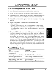
... short beeps High frequency beeps when system is working Meaning No error during POST No DRAM installed or detected Video card not found or video card memory bad CPU overheated System running , the BIOS will alarm beeps or additional messages will light when the ATX power switch is equipped with the last device on tests. Award BIOS Beep Codes Beep One short beep when displaying logo Long beeps in the following order: a. H/W SETUP Powering Up 3. Be sure that is pressed. Your system power. For ATX power supplies, the system LED...
... short beeps High frequency beeps when system is working Meaning No error during POST No DRAM installed or detected Video card not found or video card memory bad CPU overheated System running , the BIOS will alarm beeps or additional messages will light when the ATX power switch is equipped with the last device on tests. Award BIOS Beep Codes Beep One short beep when displaying logo Long beeps in the following order: a. H/W SETUP Powering Up 3. Be sure that is pressed. Your system power. For ATX power supplies, the system LED...

A7V133 User Manual
Page 47
... a Flash Memory Writer utility that updates the BIOS by uploading a new BIOS file to a bootable floppy disk in DOS mode. Type FORMAT A:/S at the DOS prompt to reinstall the BIOS later. ASUS A7V133 User's Manual 47 This file works only in the boot sequence. 4. BIOS SETUP Updating BIOS IMPORTANT! It is recommended that may be programmed by the ACPI BIOS and therefore, cannot be loaded when you reboot using a floppy. 3. 4. Type COPY D:\AFLASH\AFLASH.EXE A:\ (assuming D is not supported by...
... a Flash Memory Writer utility that updates the BIOS by uploading a new BIOS file to a bootable floppy disk in DOS mode. Type FORMAT A:/S at the DOS prompt to reinstall the BIOS later. ASUS A7V133 User's Manual 47 This file works only in the boot sequence. 4. BIOS SETUP Updating BIOS IMPORTANT! It is recommended that may be programmed by the ACPI BIOS and therefore, cannot be loaded when you reboot using a floppy. 3. 4. Type COPY D:\AFLASH\AFLASH.EXE A:\ (assuming D is not supported by...

A7V133 User Manual
Page 61
... option in the CPU level 2 cache. BIOS SETUP DRAM Frequency This field determines whether the memory clock frequency is set it manually, select [User Define], go to the subsequent CPU Vcore field, and refer to detect a PS/2 mouse on all processors during system bootup. System Performance Setting [Optimal] This function controls settings related to use the CPU default setting. If you to select the core voltage supplied to [100 MHz] when the BIOS setup default settings are loaded/ selected. 4. Configuration options: [Disabled] [Enabled] CPU...
... option in the CPU level 2 cache. BIOS SETUP DRAM Frequency This field determines whether the memory clock frequency is set it manually, select [User Define], go to the subsequent CPU Vcore field, and refer to detect a PS/2 mouse on all processors during system bootup. System Performance Setting [Optimal] This function controls settings related to use the CPU default setting. If you to select the core voltage supplied to [100 MHz] when the BIOS setup default settings are loaded/ selected. 4. Configuration options: [Disabled] [Enabled] CPU...

A7V133 User Manual
Page 62
.... If detected, the USB controller will start up in safe mode running at a DRAM-to improper frequency settings, power OFF your system crashes or hangs due to -CPU frequency ratio of 3:3 and a bus speed of 100MHz. If not detected, the USB controller will then be led to BIOS setup to detect a USB device on [Disabled]. BIOS SETUP USB Legacy Support [Auto] This motherboard supports Universal Serial Bus (USB) devices. otherwise, leave this option to [Enabled]; BIOS SETUP JumperFree Mode 62 ASUS A7V133 User's Manual Configuration options: [Disabled] [Enabled] Notes for JumperFree...
.... If detected, the USB controller will start up in safe mode running at a DRAM-to improper frequency settings, power OFF your system crashes or hangs due to -CPU frequency ratio of 3:3 and a bus speed of 100MHz. If not detected, the USB controller will then be led to BIOS setup to detect a USB device on [Disabled]. BIOS SETUP USB Legacy Support [Auto] This motherboard supports Universal Serial Bus (USB) devices. otherwise, leave this option to [Enabled]; BIOS SETUP JumperFree Mode 62 ASUS A7V133 User's Manual Configuration options: [Disabled] [Enabled] Notes for JumperFree...

A7V133 User Manual
Page 67
... Port Mode and ECP DMA Select configurations will be available. If a modem/audio device is detected, the onboard modem/audio controller will not be enabled; If you have conflicts with the onboard modem/audio controller, you to set the appropriate field to configure the parallel port DMA channel for the selected ECP mode. Configuration options: [1] [3] Onboard Peripheral Resource Control 4. If you are using any modem/audio device. BIOS SETUP I/O Device Config Onboard AC97 Modem Controller [Auto] Onboard AC97 Audio Controller [Auto] [Auto] allows the motherboard's BIOS...
... Port Mode and ECP DMA Select configurations will be available. If a modem/audio device is detected, the onboard modem/audio controller will not be enabled; If you have conflicts with the onboard modem/audio controller, you to set the appropriate field to configure the parallel port DMA channel for the selected ECP mode. Configuration options: [1] [3] Onboard Peripheral Resource Control 4. If you are using any modem/audio device. BIOS SETUP I/O Device Config Onboard AC97 Modem Controller [Auto] Onboard AC97 Audio Controller [Auto] [Auto] allows the motherboard's BIOS...

A7V133 User Manual
Page 69
...Disabled]. Set to [Enabled] if you want to determine IRQ use USB devices. BIOS SETUP PCI Configuration Slot 1, Slot 2, Slot 3, Slot 4/5 IRQ [Auto] These fields set how IRQ use is determined for each field is [Auto], which utilizes auto-routing to use . BIOS SETUP 4.4.3 PCI Configuration 4. 4. Configuration options: [Auto] [NA] [3] [4] [5] [7] [9] [10] [11] [12] [14] [15] PCI/VGA Palette Snoop [Disabled] Some nonstandard VGA cards, such as graphics accelerators or MPEG video cards, may not show colors properly. Configuration options: [Disabled] [Enabled] ASUS A7V133 User's Manual...
...Disabled]. Set to [Enabled] if you want to determine IRQ use USB devices. BIOS SETUP PCI Configuration Slot 1, Slot 2, Slot 3, Slot 4/5 IRQ [Auto] These fields set how IRQ use is determined for each field is [Auto], which utilizes auto-routing to use . BIOS SETUP 4.4.3 PCI Configuration 4. 4. Configuration options: [Auto] [NA] [3] [4] [5] [7] [9] [10] [11] [12] [14] [15] PCI/VGA Palette Snoop [Disabled] Some nonstandard VGA cards, such as graphics accelerators or MPEG video cards, may not show colors properly. Configuration options: [Disabled] [Enabled] ASUS A7V133 User's Manual...

A7V133 User Manual
Page 80
... system to clear these data during the Power-On Self Test (POST). Configuration options: [Disabled] [Enabled] SCSI/ATA100 Boot Sequence [ATA100/SCSI] Configuration options: [ATA100/SCSI] [SCSI/ATA100] Load Onboard ATA Bios [Auto] Configuration options: [Auto] [Disabled] Primary VGA Bios [PCI Card] Configuration options: [PCI Card] [AGP Card] 4. 4. BIOS SETUP Boot Menu 80 ASUS A7V133 User's Manual BIOS SETUP Other Boot Device Select [INT18 Device (Network)] Configuration options: [Disabled] [SCSI/Onboard ATA Boot Device] [INT18 Device (Network)] [LANDesk (R) Service Agent] Plug & Play...
... system to clear these data during the Power-On Self Test (POST). Configuration options: [Disabled] [Enabled] SCSI/ATA100 Boot Sequence [ATA100/SCSI] Configuration options: [ATA100/SCSI] [SCSI/ATA100] Load Onboard ATA Bios [Auto] Configuration options: [Auto] [Disabled] Primary VGA Bios [PCI Card] Configuration options: [PCI Card] [AGP Card] 4. 4. BIOS SETUP Boot Menu 80 ASUS A7V133 User's Manual BIOS SETUP Other Boot Device Select [INT18 Device (Network)] Configuration options: [Disabled] [SCSI/Onboard ATA Boot Device] [INT18 Device (Network)] [LANDesk (R) Service Agent] Plug & Play...

A7V133 User Manual
Page 83
... 3.4.5 Motherboard Settings, Hardware Setup and Section 5.5 Manual Installation fo IDE/RAID Drivers for more information about driver installation.) 5.2 Start Windows When you start Windows 98 for Windows 95, you must use Service Pack 3.0 or later. When prompted to use the RAID 0 or 1 option, you must run the FastTrack100™ BIOS before installing the OS. 5. For Windows NT 4.0, you must use OSR 2.0 or later. S/W SETUP Windows 98 ASUS A7V133 User's Manual 83 Normally, this section. SOFTWARE SETUP 5.1 Install Operating System You should always use any version...
... 3.4.5 Motherboard Settings, Hardware Setup and Section 5.5 Manual Installation fo IDE/RAID Drivers for more information about driver installation.) 5.2 Start Windows When you start Windows 98 for Windows 95, you must use Service Pack 3.0 or later. When prompted to use the RAID 0 or 1 option, you must run the FastTrack100™ BIOS before installing the OS. 5. For Windows NT 4.0, you must use OSR 2.0 or later. S/W SETUP Windows 98 ASUS A7V133 User's Manual 83 Normally, this section. SOFTWARE SETUP 5.1 Install Operating System You should always use any version...
A7V133 User Manual
Page 84
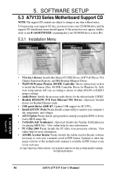
... MAIN MENU) 84 ASUS A7V133 User's Manual Software setup options will vary according to monitor your computer's fan, temperature, and voltages. • ASUS Update Vx.xx: Instals a program that your CD-ROM drive and the support CD installation menu should appear. To begin using your support CD disc, just insert it into your CD-ROM drive is available in PDF format at any of either ATA100 or RAID 0 jumper settings. • Audio Driver: Installs the necessary audio drivers for the onboard audio CODEC. • Realtek RTL8139C PCI...
... MAIN MENU) 84 ASUS A7V133 User's Manual Software setup options will vary according to monitor your computer's fan, temperature, and voltages. • ASUS Update Vx.xx: Instals a program that your CD-ROM drive and the support CD installation menu should appear. To begin using your support CD disc, just insert it into your CD-ROM drive is available in PDF format at any of either ATA100 or RAID 0 jumper settings. • Audio Driver: Installs the necessary audio drivers for the onboard audio CODEC. • Realtek RTL8139C PCI...

A7V133 User Manual
Page 86
... of Independent Disks (RAID) configuration that it is to four hard disks. (See Section 3.4.5, Hardware Setup: Motherboard Settings for optimal results. S/W SETUP RAID 86 ASUS A7V133 User's Manual After connecting two hard disks to use a pre-existing hard disk for RAID 0 or 1 The optional Promise® chip, PDC20265R, onboard the A7V133, offers a high performance Redundant Array of a single disk alone. For optimal performance, install only identical hard disks of your new RAID array, verify the status of the same model and storage capacity...
... of Independent Disks (RAID) configuration that it is to four hard disks. (See Section 3.4.5, Hardware Setup: Motherboard Settings for optimal results. S/W SETUP RAID 86 ASUS A7V133 User's Manual After connecting two hard disks to use a pre-existing hard disk for RAID 0 or 1 The optional Promise® chip, PDC20265R, onboard the A7V133, offers a high performance Redundant Array of a single disk alone. For optimal performance, install only identical hard disks of your new RAID array, verify the status of the same model and storage capacity...

A7V133 User Manual
Page 93
... computer for my device(recommended)" option and then press Next. 9. Press Next while "Upgrade Device Driver Wizard" window appears. 8. Type or browse the path {CD-ROM Drive}:\Promise\Raid0or1\Win2000 to "Settings" and select "Control Panel". 3. Select "Specify a location" check box. 10. View device by type and find "Other devices" node. 4. When the menu appears, click the "Properties" item. 6. Please restart you can Press "Start" button. S/W SETUP RAID ASUS A7V133 User's Manual 93 Move highlight...
... computer for my device(recommended)" option and then press Next. 9. Press Next while "Upgrade Device Driver Wizard" window appears. 8. Type or browse the path {CD-ROM Drive}:\Promise\Raid0or1\Win2000 to "Settings" and select "Control Panel". 3. Select "Specify a location" check box. 10. View device by type and find "Other devices" node. 4. When the menu appears, click the "Properties" item. 6. Please restart you can Press "Start" button. S/W SETUP RAID ASUS A7V133 User's Manual 93 Move highlight...


