
A7V133 User Manual
Page 2
... ANY ERRORS OR INACCURACIES THAT MAY APPEAR IN THIS MANUAL, INCLUDING THE PRODUCTS AND SOFTWARE DESCRIBED IN IT. Product Name: ASUS A7V133 / A7V133-C Manual Revision: 1.05 E743 Release Date: March 2001 2 ASUS A7V133 User's Manual ASUS PROVIDES THIS MANUAL "AS IS" WITHOUT WARRANTY OF ANY KIND, EITHER EXPRESS OR IMPLIED, INCLUDING BUT NOT LIMITED TO THE...
... ANY ERRORS OR INACCURACIES THAT MAY APPEAR IN THIS MANUAL, INCLUDING THE PRODUCTS AND SOFTWARE DESCRIBED IN IT. Product Name: ASUS A7V133 / A7V133-C Manual Revision: 1.05 E743 Release Date: March 2001 2 ASUS A7V133 User's Manual ASUS PROVIDES THIS MANUAL "AS IS" WITHOUT WARRANTY OF ANY KIND, EITHER EXPRESS OR IMPLIED, INCLUDING BUT NOT LIMITED TO THE...

A7V133 User Manual
Page 3
...) Notebook (Tel): +886-2-2890-7122 (English) Desktop/Server (Tel):+886-2-2890-7123 (English) Fax: +886-2-2893-7775 Email: tsd@asus.com.tw WWW: www.asus.com.tw FTP: ftp.asus.com.tw/pub/ASUS ASUS COMPUTER INTERNATIONAL (America) Marketing Address: 6737 Mowry Avenue, Mowry Business Center, Building 2 Newark, CA 94560, USA Fax: +1-510-608-4555... Fax: +49-2102-9599-11 Support (Email): www.asuscom.de/de/support (for online support) WWW: www.asuscom.de FTP: ftp.asuscom.de/pub/ASUSCOM ASUS A7V133 User's Manual 3
...) Notebook (Tel): +886-2-2890-7122 (English) Desktop/Server (Tel):+886-2-2890-7123 (English) Fax: +886-2-2893-7775 Email: tsd@asus.com.tw WWW: www.asus.com.tw FTP: ftp.asus.com.tw/pub/ASUS ASUS COMPUTER INTERNATIONAL (America) Marketing Address: 6737 Mowry Avenue, Mowry Business Center, Building 2 Newark, CA 94560, USA Fax: +1-510-608-4555... Fax: +49-2102-9599-11 Support (Email): www.asuscom.de/de/support (for online support) WWW: www.asuscom.de FTP: ftp.asuscom.de/pub/ASUSCOM ASUS A7V133 User's Manual 3

A7V133 User Manual
Page 4
... the Computer System 47 4.1.2 Updating BIOS Procedures 48 4.2 BIOS Setup Program 50 4.2.1 BIOS Menu Bar 51 4.2.2 Legend Bar 52 4.3 Main Menu 54 4 ASUS A7V133 User's Manual INTRODUCTION 7 1.1 How This Manual Is Organized 7 1.2 Item Checklist 7 2. FEATURES 8 2.1 The ASUS A7V133 8 2.1.1 Specifications 8 2.1.2 Special Features 10 2.1.3 Performance Features 10 2.1.4 Intelligence 11 2.2 Motherboard Components 12 2.2.1 Component Locations 13 3. CONTENTS 1.
... the Computer System 47 4.1.2 Updating BIOS Procedures 48 4.2 BIOS Setup Program 50 4.2.1 BIOS Menu Bar 51 4.2.2 Legend Bar 52 4.3 Main Menu 54 4 ASUS A7V133 User's Manual INTRODUCTION 7 1.1 How This Manual Is Organized 7 1.2 Item Checklist 7 2. FEATURES 8 2.1 The ASUS A7V133 8 2.1.1 Specifications 8 2.1.2 Special Features 10 2.1.3 Performance Features 10 2.1.4 Intelligence 11 2.2 Motherboard Components 12 2.2.1 Component Locations 13 3. CONTENTS 1.

A7V133 User Manual
Page 5
...-L101 Fast Ethernet Card 103 7.2 Modem Riser 105 7.3 Glossary 107 ASUS A7V133 User's Manual 5 SOFTWARE REFERENCE 94 6.1 ASUS PC Probe 94 6.2 CyberLink PowerPlayer SE 99 6.3 CyberLink PowerDVD 100 6.4 CyberLink VideoLive Mail 101 7. SOFTWARE SETUP 83 5.1 Install Operating System 83 5.2 Start Windows 83 5.3 A7V133 Series Motherboard Support CD 84 5.4 Using the Promise® Chip for...
...-L101 Fast Ethernet Card 103 7.2 Modem Riser 105 7.3 Glossary 107 ASUS A7V133 User's Manual 5 SOFTWARE REFERENCE 94 6.1 ASUS PC Probe 94 6.2 CyberLink PowerPlayer SE 99 6.3 CyberLink PowerDVD 100 6.4 CyberLink VideoLive Mail 101 7. SOFTWARE SETUP 83 5.1 Install Operating System 83 5.2 Start Windows 83 5.3 A7V133 Series Motherboard Support CD 84 5.4 Using the Promise® Chip for...

A7V133 User Manual
Page 6
... found to comply with FCC Rules Part 15. Cet appareil numérique de la classe B est conforme à la norme NMB-003 du Canada. 6 ASUS A7V133 User's Manual FCC & DOC COMPLIANCE Federal Communications Commission Statement This device complies with the limits for a Class B digital device, pursuant to Part 15 of the...
... found to comply with FCC Rules Part 15. Cet appareil numérique de la classe B est conforme à la norme NMB-003 du Canada. 6 ASUS A7V133 User's Manual FCC & DOC COMPLIANCE Federal Communications Commission Statement This device complies with the limits for a Class B digital device, pursuant to Part 15 of the...

A7V133 User Manual
Page 7
... (2) 40-pin 80-conductor ribbon cable for internal UltraDMA/ 100 / UltraDMA/66 (also compatible with drivers and utilities (1) This Motherboard User's Manual ASUS A7V133 User's Manual 7 HARDWARE SETUP 4. FEATURES 3. APPENDIX Manual information and checklist Production information and specifications Intructions on setting up the motherboard. BIOS SETUP 5. INTRODUCTION 2. SOFTWARE SETUP 6. ...
... (2) 40-pin 80-conductor ribbon cable for internal UltraDMA/ 100 / UltraDMA/66 (also compatible with drivers and utilities (1) This Motherboard User's Manual ASUS A7V133 User's Manual 7 HARDWARE SETUP 4. FEATURES 3. APPENDIX Manual information and checklist Production information and specifications Intructions on setting up the motherboard. BIOS SETUP 5. INTRODUCTION 2. SOFTWARE SETUP 6. ...

A7V133 User Manual
Page 8
complies with support for 4X, 2X, and 1X AGP modes; AC97 audio; Easy-to each other. 8 ASUS A7V133 User's Manual Data "striping," or RAID 0, improves speed performance as the protocol optimizes two identical hard disks to write data to -use DIP switches ... Promise IDE controller chip supports the PCI ATA-100 controller protocol and Ultra DMA/100 data transfer speeds. FEATURES 2.1 The ASUS A7V133 / A7V133-C The ASUS A7V133 motherboard is enabled. and PCI 2.2. USB controller with root hub and four function ports. • PC133 SDRAM / VC133 VCM Support: Equipped with support for ...
complies with support for 4X, 2X, and 1X AGP modes; AC97 audio; Easy-to each other. 8 ASUS A7V133 User's Manual Data "striping," or RAID 0, improves speed performance as the protocol optimizes two identical hard disks to write data to -use DIP switches ... Promise IDE controller chip supports the PCI ATA-100 controller protocol and Ultra DMA/100 data transfer speeds. FEATURES 2.1 The ASUS A7V133 / A7V133-C The ASUS A7V133 motherboard is enabled. and PCI 2.2. USB controller with root hub and four function ports. • PC133 SDRAM / VC133 VCM Support: Equipped with support for ...

A7V133 User Manual
Page 9
...examine and manage system status information, such as CPU and systerm voltages, temperatures, and fan status through the onboard hardware ASUS ASIC and the bundled ASUS PC Probe. • SMBus: Features the System Management Bus interface, which is autodetected to enable/disable suspend-to-RAM... gadgets, or an optional remote controller. • Desktop Management Interface (DMI): Supports DMI through an optional ASUS PCI-L101 10/100 Fast Ethernet PCI card (see 7. ASUS A7V133 User's Manual 9 2. FEATURES • UltraDMA/100 Support: Comes with an onboard PCI Bus Master IDE controller...
...examine and manage system status information, such as CPU and systerm voltages, temperatures, and fan status through the onboard hardware ASUS ASIC and the bundled ASUS PC Probe. • SMBus: Features the System Management Bus interface, which is autodetected to enable/disable suspend-to-RAM... gadgets, or an optional remote controller. • Desktop Management Interface (DMI): Supports DMI through an optional ASUS PCI-L101 10/100 Fast Ethernet PCI card (see 7. ASUS A7V133 User's Manual 9 2. FEATURES • UltraDMA/100 Support: Comes with an onboard PCI Bus Master IDE controller...

A7V133 User Manual
Page 10
.../100 require a 40-pin 80-conductor cable to the memory and processor. • High-Speed Data Transfer Interface: IDE transfers using PC100-compliant SDRAMs). 10 ASUS A7V133 User's Manual This motherboard also supports standard SDRAM, which increases the data transfer rate (1.064GB/s max using PC133-compliant SDRAMs and 800MB/s max using UltraDMA...
.../100 require a 40-pin 80-conductor cable to the memory and processor. • High-Speed Data Transfer Interface: IDE transfers using PC100-compliant SDRAMs). 10 ASUS A7V133 User's Manual This motherboard also supports standard SDRAM, which increases the data transfer rate (1.064GB/s max using PC133-compliant SDRAMs and 800MB/s max using UltraDMA...

A7V133 User Manual
Page 11
The system resource monitor will warn the user before the system resources are messages waiting in 4.5 Power Menu). ASUS A7V133 User's Manual 11 2. When the power button is kept in memory on the BIOS or OS setting (see PWR Button < 4 Secs in the mailbox. A ... user. • Remote Ring On (requires modem): This allows a computer to be monitored for more than 4 seconds when the system is monitored by the ASUS ASIC to prevent system overheat and system damage. • Voltage Monitoring and Alert: System voltage levels are monitored to ensure stable voltage to present enormous...
The system resource monitor will warn the user before the system resources are messages waiting in 4.5 Power Menu). ASUS A7V133 User's Manual 11 2. When the power button is kept in memory on the BIOS or OS setting (see PWR Button < 4 Secs in the mailbox. A ... user. • Remote Ring On (requires modem): This allows a computer to be monitored for more than 4 seconds when the system is monitored by the ASUS ASIC to prevent system overheat and system damage. • Voltage Monitoring and Alert: System voltage levels are monitored to ensure stable voltage to present enormous...

A7V133 User Manual
Page 12
... (on audio model only) ... (Bottom) 23 Network Features Wake-On-LAN Connector 17 Wake-On-Ring Connector 13 Hardware Monitoring System Voltage Monitoring (integrated in ASUS ASIC) ....... 15 3 Fan Power and Speed Monitoring Connectors Power ATX Power Supply Connector 5 Special Feature Onboard LED 21 Promise® Ultra DMA/100 Chip (optional...
... (on audio model only) ... (Bottom) 23 Network Features Wake-On-LAN Connector 17 Wake-On-Ring Connector 13 Hardware Monitoring System Voltage Monitoring (integrated in ASUS ASIC) ....... 15 3 Fan Power and Speed Monitoring Connectors Power ATX Power Supply Connector 5 Special Feature Onboard LED 21 Promise® Ultra DMA/100 Chip (optional...

A7V133 User Manual
Page 13
FEA TURES Motherboard Parts 2. FEATURES 2.2.1 Component Locations 1 2 3 4 56 7 8 28 27 26 25 24 23 22 21 20 19 - 18 17 16 15 14 13 12 1110 9 ASUS A7V133 User's Manual 13 2.
FEA TURES Motherboard Parts 2. FEATURES 2.2.1 Component Locations 1 2 3 4 56 7 8 28 27 26 25 24 23 22 21 20 19 - 18 17 16 15 14 13 12 1110 9 ASUS A7V133 User's Manual 13 2.

A7V133 User Manual
Page 14
... PRO) PLED SMB PCI Slot 1 PCI Slot 2 VIA VT82C686B ATA100 IDE Controller MODEM SPK ADN# AUD_EN2 AUD_EN1 PCI Slot 3 PCI Slot 4 A7V133 WOLCON PCI Slot 5 Audio Modem Riser (AMR) WOR ASUS ASIC JEN AS99127F USBPORT CHASSIS JP13 JP14 IR IDELED PANEL Grayed components are optional at the time of purchase (JTCPU is...
... PRO) PLED SMB PCI Slot 1 PCI Slot 2 VIA VT82C686B ATA100 IDE Controller MODEM SPK ADN# AUD_EN2 AUD_EN1 PCI Slot 3 PCI Slot 4 A7V133 WOLCON PCI Slot 5 Audio Modem Riser (AMR) WOR ASUS ASIC JEN AS99127F USBPORT CHASSIS JP13 JP14 IR IDELED PANEL Grayed components are optional at the time of purchase (JTCPU is...

A7V133 User Manual
Page 15
3. ASUS A7V133 User's Manual H/W SETUP Layout Contents Motherboard Settings 1) DSW p. 18 DIP Switches 2) JEN p. 18 JumperFree Mode (JumperFree/Jumper Mode) 3) AUDIOCODEC p. 19 Onboard Audio Setting (Enable/Enable) (...
3. ASUS A7V133 User's Manual H/W SETUP Layout Contents Motherboard Settings 1) DSW p. 18 DIP Switches 2) JEN p. 18 JumperFree Mode (JumperFree/Jumper Mode) 3) AUDIOCODEC p. 19 Onboard Audio Setting (Enable/Enable) (...
A7V133 User Manual
Page 16
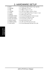
3. H/W SETUP Layout Contents ASUS A7V133 User's Manual HARDWARE SETUP 16) MIC2 17) USBPORT 18) SMB 19) ATXPWR 20) JTPWR 21) IDELED 22) SPEAKER (PANEL) 23) PWR.LED (PANEL) 24) MSG....
3. H/W SETUP Layout Contents ASUS A7V133 User's Manual HARDWARE SETUP 16) MIC2 17) USBPORT 18) SMB 19) ATXPWR 20) JTPWR 21) IDELED 22) SPEAKER (PANEL) 23) PWR.LED (PANEL) 24) MSG....
A7V133 User Manual
Page 17
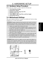
.... 1. If you work on the inside. 2. Ensure that the system is switched off mode and not powered OFF. 01 01 01 A7V133 A7V133 Onboard LED ON Standby Power OFF Powered Off ASUS A7V133 User's Manual The onboard LED when lit acts as the power supply case. 3. Install Expansion Cards 5. Setup the BIOS Software 3.4 Motherboard...
.... 1. If you work on the inside. 2. Ensure that the system is switched off mode and not powered OFF. 01 01 01 A7V133 A7V133 Onboard LED ON Standby Power OFF Powered Off ASUS A7V133 User's Manual The onboard LED when lit acts as the power supply case. 3. Install Expansion Cards 5. Setup the BIOS Software 3.4 Motherboard...

A7V133 User Manual
Page 18
... Jumper Mode DSW VID JEN (See #7 External (See #9 Voltage [1-2] Frequency Setting) Regulator Output) JumperFree™Mode All OFF All [3-4] [2-3] (Default) Jumper Mode JumperFree Mode (Default) A7V133 A7V133 Jumper Mode Settings See Frequency External Setting DSW 54 3 2 1 OFF ON ON See Voltage Reg. Frequency Selection 3. 3. H/W SETUP Motherboard Settings 01 01 01 01 01.... HARDWARE SETUP 1) Motherboard Features Settings (DIP Switches - The default setting is OFF. Frequency Selection 4. Out. (VID) 1234 VID4 VID3 VID2 VID1 JEN 12 JEN 23 ASUS A7V133 User's Manual
... Jumper Mode DSW VID JEN (See #7 External (See #9 Voltage [1-2] Frequency Setting) Regulator Output) JumperFree™Mode All OFF All [3-4] [2-3] (Default) Jumper Mode JumperFree Mode (Default) A7V133 A7V133 Jumper Mode Settings See Frequency External Setting DSW 54 3 2 1 OFF ON ON See Voltage Reg. Frequency Selection 3. 3. H/W SETUP Motherboard Settings 01 01 01 01 01.... HARDWARE SETUP 1) Motherboard Features Settings (DIP Switches - The default setting is OFF. Frequency Selection 4. Out. (VID) 1234 VID4 VID3 VID2 VID1 JEN 12 JEN 23 ASUS A7V133 User's Manual

A7V133 User Manual
Page 19
HARDWARE SETUP 3) Onboard Audio Setting (AUDIOCODEC) The onboard audio CODEC may be disabled. H/W SETUP Motherboard Settings ASUS A7V133 User's Manual NOTE: This setting is available only on the AMR slot. If using a PCI audio expansion card, Onboard ... a primary AMR on motherboards with the onboard audio option. Setting Enable Disable AUDIOCODEC [1-2] [1-2] [1-2] [1-2] (default) [2-3] [2-3] [2-3] [2-3] 01 01 01 A7V133 A7V133 Audio Codec Setting Enable Onboard Audio Codec (Default) 12 SPK ADN# AUD_EN2 AUD_EN1 Disable Onboard Audio Codec 23 SPK ADN# AUD_EN2 AUD_EN1 3. 3.
HARDWARE SETUP 3) Onboard Audio Setting (AUDIOCODEC) The onboard audio CODEC may be disabled. H/W SETUP Motherboard Settings ASUS A7V133 User's Manual NOTE: This setting is available only on the AMR slot. If using a PCI audio expansion card, Onboard ... a primary AMR on motherboards with the onboard audio option. Setting Enable Disable AUDIOCODEC [1-2] [1-2] [1-2] [1-2] (default) [2-3] [2-3] [2-3] [2-3] 01 01 01 A7V133 A7V133 Audio Codec Setting Enable Onboard Audio Codec (Default) 12 SPK ADN# AUD_EN2 AUD_EN1 Disable Onboard Audio Codec 23 SPK ADN# AUD_EN2 AUD_EN1 3. 3.

A7V133 User Manual
Page 20
... if changing this jumper to PCI devices. H/W SETUP Motherboard Settings 21 21 JP13 JP14 32 RAID 0 or 1 ATA100 A7V133 A7V133 ATA100/RAID0 Selection (Default) ASUS A7V133 User's Manual HARDWARE SETUP 4) PCI 3Volt Setting (3VSBSLT) This jumper allows you to select the voltage supplied to 3 ... 3. 01 01 01 01 01 01 3. Setting 3 Volt 3 VSB 3VSBSLT [1-2] [2-3] (default) 3VSBSLT 12 23 Add 3 Volt Add 3 VSB (Default) A7V133 A7V133 PCI 3Volt Selection 5) ATA100 / RAID 0 or 1 Setting (ATA100/RAID 0 or 1) Jumper 13 and 14 specifies the function of Software Setup: Using the ...
... if changing this jumper to PCI devices. H/W SETUP Motherboard Settings 21 21 JP13 JP14 32 RAID 0 or 1 ATA100 A7V133 A7V133 ATA100/RAID0 Selection (Default) ASUS A7V133 User's Manual HARDWARE SETUP 4) PCI 3Volt Setting (3VSBSLT) This jumper allows you to select the voltage supplied to 3 ... 3. 01 01 01 01 01 01 3. Setting 3 Volt 3 VSB 3VSBSLT [1-2] [2-3] (default) 3VSBSLT 12 23 Add 3 Volt Add 3 VSB (Default) A7V133 A7V133 PCI 3Volt Selection 5) ATA100 / RAID 0 or 1 Setting (ATA100/RAID 0 or 1) Jumper 13 and 14 specifies the function of Software Setup: Using the ...

A7V133 User Manual
Page 21
... result in the shortening of your computer component's life. H/W SETUP Motherboard Settings ASUS A7V133 User's Manual Setting 3.30 Volt 3.45 Volt test mode VIO [1-2] [2-3] (default) [3-4] 01 01 01 12 3.30 Volt VIO 23 34 3.45 Volt (Default) test mode A7V133 A7V133 VIO Setting WARNING! It is strongly recommended that you to select the voltage...
... result in the shortening of your computer component's life. H/W SETUP Motherboard Settings ASUS A7V133 User's Manual Setting 3.30 Volt 3.45 Volt test mode VIO [1-2] [2-3] (default) [3-4] 01 01 01 12 3.30 Volt VIO 23 34 3.45 Volt (Default) test mode A7V133 A7V133 VIO Setting WARNING! It is strongly recommended that you to select the voltage...


