A7S-VM User Manual
Page 3
... Center, Building 2 Newark, CA 94560, USA Fax: +1-510-608-4555 Email: tmd1@asus.com Technical Support Fax: +1-510-608-4555 Email: tsd@asus.com WWW: www.asus.com FTP: ftp.asus.com/Pub/ASUS ASUS COMPUTER GmbH (Europe) Marketing Address: Harkortstr. 25, 40880 Ratingen, BRD, Germany Fax: ....de (for marketing requests only) Technical Support Hotline: MB/Others: +49-2102-9599-0 Notebook: +49-2102-9599-10 Fax: +49-2102-9599-11 Support (Email): www.asuscom.de/de/support (for online support) WWW: www.asuscom.de FTP: ftp.asuscom.de/pub/ASUSCOM ASUS A7S-VM User's Manual 3
... Center, Building 2 Newark, CA 94560, USA Fax: +1-510-608-4555 Email: tmd1@asus.com Technical Support Fax: +1-510-608-4555 Email: tsd@asus.com WWW: www.asus.com FTP: ftp.asus.com/Pub/ASUS ASUS COMPUTER GmbH (Europe) Marketing Address: Harkortstr. 25, 40880 Ratingen, BRD, Germany Fax: ....de (for marketing requests only) Technical Support Hotline: MB/Others: +49-2102-9599-0 Notebook: +49-2102-9599-10 Fax: +49-2102-9599-11 Support (Email): www.asuscom.de/de/support (for online support) WWW: www.asuscom.de FTP: ftp.asuscom.de/pub/ASUSCOM ASUS A7S-VM User's Manual 3
A7S-VM User Manual
Page 5
APPENDIX 83 7.1 Glossary 83 INDEX 87 ASUS A7S-VM User's Manual 5 CONTENTS 4.3 Main Menu 48 4.3.1 Primary & Secondary Master/Slave 49 4.3.2 Keyboard Features 52 4.4 Advanced Menu 54 4.4.1 Chip Configuration 56 4.4.2 I/O Device ...4.4.4 Shadow Configuration 65 4.5 Power Menu 66 4.5.1 Power Up Control 68 4.5.2 Hardware Monitor 69 4.6 Boot Menu 70 4.7 Exit Menu 72 5. SOFTWARE REFERENCE 77 6.1 ASUS PC Probe 77 7. SOFTWARE SETUP 75 5.1 Operating Systems 75 5.1.1 Windows 98 First Time Installation 75 5.2 A7S-VM Motherboard Support CD 75 5.2.1 Installation Menus 75 6.
APPENDIX 83 7.1 Glossary 83 INDEX 87 ASUS A7S-VM User's Manual 5 CONTENTS 4.3 Main Menu 48 4.3.1 Primary & Secondary Master/Slave 49 4.3.2 Keyboard Features 52 4.4 Advanced Menu 54 4.4.1 Chip Configuration 56 4.4.2 I/O Device ...4.4.4 Shadow Configuration 65 4.5 Power Menu 66 4.5.1 Power Up Control 68 4.5.2 Hardware Monitor 69 4.6 Boot Menu 70 4.7 Exit Menu 72 5. SOFTWARE REFERENCE 77 6.1 ASUS PC Probe 77 7. SOFTWARE SETUP 75 5.1 Operating Systems 75 5.1.1 Windows 98 First Time Installation 75 5.2 A7S-VM Motherboard Support CD 75 5.2.1 Installation Menus 75 6.

A7S-VM User Manual
Page 7
... on setting up the included software Reference material for two 3.5" floppy disk drives (1) ASUS Support CD with drivers and utilities ASUS IrDA-compliant infrared module (1) Bag of spare jumper caps (1) ASUS 2-port USB Connector Set (1) I/O Plate (on setting up the motherboard. INTRODUCTION Manual... information and checklist Production information and specifications Instructions on LAN models only) (1) User's Manual ASUS A7S-VM User's Manual 7 BIOS SETUP 5. INTRODUCTION 1.1 How This Manual Is Organized This manual is complete. SOFTWARE REFERENCE 7. FEATURES 3. 1.
... on setting up the included software Reference material for two 3.5" floppy disk drives (1) ASUS Support CD with drivers and utilities ASUS IrDA-compliant infrared module (1) Bag of spare jumper caps (1) ASUS 2-port USB Connector Set (1) I/O Plate (on setting up the motherboard. INTRODUCTION Manual... information and checklist Production information and specifications Instructions on LAN models only) (1) User's Manual ASUS A7S-VM User's Manual 7 BIOS SETUP 5. INTRODUCTION 1.1 How This Manual Is Organized This manual is complete. SOFTWARE REFERENCE 7. FEATURES 3. 1.

A7S-VM User Manual
Page 8
... for wireless interface. • Wake-On-LAN: Supports Wake-On-LAN activity through a WOL connector or an optional ASUS PCI-L101 10/100 Fast Ethernet PCI card. • Wake-On-Ring: Supports Wake-On-Ring activity through the onboard hardware ASUS ASIC and the bundled ASUS PC Probe. 8 ASUS A7S-VM User's Manual The chipset integrates the Ultra...
... for wireless interface. • Wake-On-LAN: Supports Wake-On-LAN activity through a WOL connector or an optional ASUS PCI-L101 10/100 Fast Ethernet PCI card. • Wake-On-Ring: Supports Wake-On-Ring activity through the onboard hardware ASUS ASIC and the bundled ASUS PC Probe. 8 ASUS A7S-VM User's Manual The chipset integrates the Ultra...

A7S-VM User Manual
Page 9
The AFPANEL connector on -chip sample rate converter, and a professional wavetable. • Connectivity Interface: Supports an optional ASUS iPanel, an easy-to-access box with system diagnostic display area, system status LEDs, USB ports, and hot keys. FEATURES Specifications 2. ASUS A7S-VM User's Manual 9 FEATURES • SMBus: Features the System Management Bus interface used to physically...
The AFPANEL connector on -chip sample rate converter, and a professional wavetable. • Connectivity Interface: Supports an optional ASUS iPanel, an easy-to-access box with system diagnostic display area, system status LEDs, USB ports, and hot keys. FEATURES Specifications 2. ASUS A7S-VM User's Manual 9 FEATURES • SMBus: Features the System Management Bus interface used to physically...

A7S-VM User Manual
Page 10
...busses to the memory and processor. 10 ASUS A7S-VM User's Manual The new PC'99 requirements for UltraDMA/100 through the onboard IDE bus master controller triples the UltraDMA/33 burst transfer rate. To fully utilize the ACPI benefits, use an ACPI-supported OS such as required by PC'99....easy as Windows 98/2000/Millenium. • PC'99 Compliant: Both the BIOS and hardware levels of ASUS smart series motherboards are based on the following high-level goals: Support for Plugn-Play compatibility and power management for configuring and managing all system components, and 32-bit device ...
...busses to the memory and processor. 10 ASUS A7S-VM User's Manual The new PC'99 requirements for UltraDMA/100 through the onboard IDE bus master controller triples the UltraDMA/33 burst transfer rate. To fully utilize the ACPI benefits, use an ACPI-supported OS such as required by PC'99....easy as Windows 98/2000/Millenium. • PC'99 Compliant: Both the BIOS and hardware levels of ASUS smart series motherboards are based on the following high-level goals: Support for Plugn-Play compatibility and power management for configuring and managing all system components, and 32-bit device ...
A7S-VM User Manual
Page 11
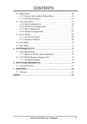
... user interfaces and run large applications. 2. Suggestions provide the user some information on managing their limited resources more protection. ASUS A7S-VM User's Manual 11 FEATURES 2.1.3 Intelligence • Auto Fan Off: The system fans powers off the computer remotely through an...4.5 Power Menu). A chassis intrusion event is necessary to ensure proper system configuration and management. • Chassis Intrusion Detection: Supports chassis-intrusion monitoring through the thermal sensor of the BIOS setting. • Fan Status Monitoring and Alarm: To prevent system ...
... user interfaces and run large applications. 2. Suggestions provide the user some information on managing their limited resources more protection. ASUS A7S-VM User's Manual 11 FEATURES 2.1.3 Intelligence • Auto Fan Off: The system fans powers off the computer remotely through an...4.5 Power Menu). A chassis intrusion event is necessary to ensure proper system configuration and management. • Chassis Intrusion Detection: Supports chassis-intrusion monitoring through the thermal sensor of the BIOS setting. • Fan Status Monitoring and Alarm: To prevent system ...
A7S-VM User Manual
Page 12
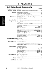
... Main Memory 2 DIMM Sockets for locations. FEATURES 2.2 Motherboard Components See opposite page for up to 1GB Memory Support 4 PC133 SDRAM support Expansion Slots 4 PCI Slots 18 System I/O Floppy Disk Drive Connector 6 IDE Connectors (UltraDMA/100 Support 5 ASUS iPanel Connectors 9, 16 Parallel Port Top) 21 Serial Port 1 (COM1 Bottom Left) 21 Serial Port 2 (COM2 14...) 20 Microphone Connector Bottom) 20 Special Features Wake-On-LAN Connector 12 Wake-On-Ring Connector 7 Power ATX Power Connector 1 Form Factor Micro ATX 12 ASUS A7S-VM User's Manual 2.
... Main Memory 2 DIMM Sockets for locations. FEATURES 2.2 Motherboard Components See opposite page for up to 1GB Memory Support 4 PC133 SDRAM support Expansion Slots 4 PCI Slots 18 System I/O Floppy Disk Drive Connector 6 IDE Connectors (UltraDMA/100 Support 5 ASUS iPanel Connectors 9, 16 Parallel Port Top) 21 Serial Port 1 (COM1 Bottom Left) 21 Serial Port 2 (COM2 14...) 20 Microphone Connector Bottom) 20 Special Features Wake-On-LAN Connector 12 Wake-On-Ring Connector 7 Power ATX Power Connector 1 Form Factor Micro ATX 12 ASUS A7S-VM User's Manual 2.

A7S-VM User Manual
Page 15
...) p. 17 USB Wake Up Jumper p. 17 Keyboard Wake-up Jumper p. 18 Clear RTC RAM p. 19 System Memory Support p. 21 CPU Support p. 23 32-bit PCI Bus Expansion Slots p. 25 PS/2 Mouse Port (6-pin female) p. 25 PS/2 Keyboard Port... pin) p. 32 SMBus Connector (5-1 pin) p. 33 Standard Infrared Module Connector (5-pin) p. 33 Consumer Infrared Module Connector (5-pin) p. 34 ASUS iPanel Connector (12-1 pin) p. 34 Audio Panel Connector (12-1 pin) p. 35 USB Headers (two 10-1 pin) p. 35 Internal Audio...p. 38 ATX / Soft-Off Switch Lead (2-pin) p. 38 Reset Switch Lead (2-pin) ASUS A7S-VM User's Manual 15 3.
...) p. 17 USB Wake Up Jumper p. 17 Keyboard Wake-up Jumper p. 18 Clear RTC RAM p. 19 System Memory Support p. 21 CPU Support p. 23 32-bit PCI Bus Expansion Slots p. 25 PS/2 Mouse Port (6-pin female) p. 25 PS/2 Keyboard Port... pin) p. 32 SMBus Connector (5-1 pin) p. 33 Standard Infrared Module Connector (5-pin) p. 33 Consumer Infrared Module Connector (5-pin) p. 34 ASUS iPanel Connector (12-1 pin) p. 34 Audio Panel Connector (12-1 pin) p. 35 USB Headers (two 10-1 pin) p. 35 Internal Audio...p. 38 ATX / Soft-Off Switch Lead (2-pin) p. 38 Reset Switch Lead (2-pin) ASUS A7S-VM User's Manual 15 3.

A7S-VM User Manual
Page 19
One side (with higher pin density than 18 chips are not supported on bootup screen. • Single-sided DIMMs come in 32, 64, 128, 256, 512MB. H/W SETUP System Memory ASUS A7S-VM User's Manual 19 Two DIMM sockets are generally thinner with memory chips) of the DIMM takes up to ...Max. 1GB) Total Memory x1 x1 = 3.5.1 General DIMM Notes • DIMMs that the DIMM you use only PC100-/PC133- compliant DIMMs. • ASUS motherboards support Serial Presence Detect (SPD) DIMMs. This is the memory of choice for a system memory configuration of 16, 32, 64, 128, 256, or 512MB...
One side (with higher pin density than 18 chips are not supported on bootup screen. • Single-sided DIMMs come in 32, 64, 128, 256, 512MB. H/W SETUP System Memory ASUS A7S-VM User's Manual 19 Two DIMM sockets are generally thinner with memory chips) of the DIMM takes up to ...Max. 1GB) Total Memory x1 x1 = 3.5.1 General DIMM Notes • DIMMs that the DIMM you use only PC100-/PC133- compliant DIMMs. • ASUS motherboards support Serial Presence Detect (SPD) DIMMs. This is the memory of choice for a system memory configuration of 16, 32, 64, 128, 256, or 512MB...

A7S-VM User Manual
Page 20
... have different pin contacts on each side and have a higher pin density than DRAM SIMMs. 20 Pins 60 Pins 88 Pins A7S-VM A7S-VM 168-Pin DIMM Sockets Lock The DIMMs must tell your retailer the correct DIMM type before purchasing. Make sure that you unplug the... or right to identify the type and also to both the motherboard and expansion cards (see the figure below). 3. This motherboard supports four clock signals per DIMM. 20 ASUS A7S-VM User's Manual H/W SETUP System Memory The notches on the DIMMs (see 3.3 Hardware Setup Procedure for more information). Because the number...
... have different pin contacts on each side and have a higher pin density than DRAM SIMMs. 20 Pins 60 Pins 88 Pins A7S-VM A7S-VM 168-Pin DIMM Sockets Lock The DIMMs must tell your retailer the correct DIMM type before purchasing. Make sure that you unplug the... or right to identify the type and also to both the motherboard and expansion cards (see the figure below). 3. This motherboard supports four clock signals per DIMM. 20 ASUS A7S-VM User's Manual H/W SETUP System Memory The notches on the DIMMs (see 3.3 Hardware Setup Procedure for more information). Because the number...
A7S-VM User Manual
Page 21
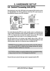
It is for the supported CPUs listed in the illustration that you match the marked corner of the CPU with the corresponding corner on how to damage the CPU pins. ..., the heatsink and fan are already attached to overheat and may damage both the CPU and the motherboard. BLANK LEVER LOCK AMD™ Athlon NOTCH A7S-VM A7S-VM Socket A Note in section 2.1.1 Specifications. ASUS A7S-VM User's Manual 21
It is for the supported CPUs listed in the illustration that you match the marked corner of the CPU with the corresponding corner on how to damage the CPU pins. ..., the heatsink and fan are already attached to overheat and may damage both the CPU and the motherboard. BLANK LEVER LOCK AMD™ Athlon NOTCH A7S-VM A7S-VM Socket A Note in section 2.1.1 Specifications. ASUS A7S-VM User's Manual 21

A7S-VM User Manual
Page 23
...the slot with the expansion card and make any . (see section 4.4.3 PCI Configuration to install expansion cards. H/W SETUP Expansion Cards ASUS A7S-VM User's Manual 23 Replace the system cover. 6. Unplug the system power cord when adding or removing expansion cards or other system components...place. 4. Failure to do so may need to change the settings.) 7. HARDWARE SETUP 3.7 Expansion Cards In the future, you intend to support these cards. The motherboard has five PCI expansion slots to use . 3. Change the necessary BIOS settings, if any necessary hardware settings for ...
...the slot with the expansion card and make any . (see section 4.4.3 PCI Configuration to install expansion cards. H/W SETUP Expansion Cards ASUS A7S-VM User's Manual 23 Replace the system cover. 6. Unplug the system power cord when adding or removing expansion cards or other system components...place. 4. Failure to do so may need to change the settings.) 7. HARDWARE SETUP 3.7 Expansion Cards In the future, you intend to support these cards. The motherboard has five PCI expansion slots to use . 3. Change the necessary BIOS settings, if any necessary hardware settings for ...

A7S-VM User Manual
Page 24
... or PCI devices. IMPORTANT: If using PCI cards on shared slots, make sure that the drivers support "Share IRQ" or that will make the system unstable or cards inoperable. shared - shared - - - shared - shared 24 ASUS A7S-VM User's Manual Interrupt Request Table for this table when configuring your motherboard also has MIDI enabled, another...
... or PCI devices. IMPORTANT: If using PCI cards on shared slots, make sure that the drivers support "Share IRQ" or that will make the system unstable or cards inoperable. shared - shared - - - shared - shared 24 ASUS A7S-VM User's Manual Interrupt Request Table for this table when configuring your motherboard also has MIDI enabled, another...

A7S-VM User Manual
Page 27
... (15-pin female) 8) Game/MIDI Connector (Gold 15-pin GAME_AUDIO) (optional) This connector supports a joystick or a game pad for playing games, and MIDI devices for a VGA monitor and other audio sources. Line Out Line In Mic 1/8" Stereo Audio Connectors ASUS A7S-VM User's Manual 27 3. Game/MIDI (15-pin female) 3. The Mic (pink) connects...
... (15-pin female) 8) Game/MIDI Connector (Gold 15-pin GAME_AUDIO) (optional) This connector supports a joystick or a game pad for playing games, and MIDI devices for a VGA monitor and other audio sources. Line Out Line In Mic 1/8" Stereo Audio Connectors ASUS A7S-VM User's Manual 27 3. Game/MIDI (15-pin female) 3. The Mic (pink) connects...

A7S-VM User Manual
Page 28
Placing jumper caps over these connector pins will cause damage to PIN 1 PIN 1 A7S-VM A7S-VM Floppy Disk Drive Connector 28 ASUS A7S-VM User's Manual NOTE: Orient the red markings on the other end to the floppy drives. (Pin 5 is usually on the side ... to prevent inserting in the Motherboard Layout. H/W SETUP Connectors IDELED A7S-VM A7S-VM IDE Activity TIP: If the case-mounted LED does not light, try reversing the 2-pin plug. 2) Floppy Disk Drive Connector (34-1 pin FLOPPY) This connector supports the provided floppy drive ribbon cable. Some pins are clearly distinguished ...
Placing jumper caps over these connector pins will cause damage to PIN 1 PIN 1 A7S-VM A7S-VM Floppy Disk Drive Connector 28 ASUS A7S-VM User's Manual NOTE: Orient the red markings on the other end to the floppy drives. (Pin 5 is usually on the side ... to prevent inserting in the Motherboard Layout. H/W SETUP Connectors IDELED A7S-VM A7S-VM IDE Activity TIP: If the case-mounted LED does not light, try reversing the 2-pin plug. 2) Floppy Disk Drive Connector (34-1 pin FLOPPY) This connector supports the provided floppy drive ribbon cable. Some pins are clearly distinguished ...
A7S-VM User Manual
Page 29
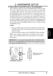
... 40-pin 80-conductor IDE cables for the jumper settings. The UltraDMA/66 cable included in the motherboard package also supports UltraDMA/100 devices. PIN 1 ASUS A7S-VM User's Manual 29 Pin 20 on each IDE connector is intentional. The hole near the blue connector on the UltraDMA...Masters with two ribbon cables - If you have more than two UltraDMA/100/66/33 devices, purchase another for the secondary IDE connector. A7S-VM A7S-VM IDE Connectors NOTE: Orient the red markings (usually zigzag) on the UltraDMA cable connector. H/W SETUP Connectors 3. If you install two hard...
... 40-pin 80-conductor IDE cables for the jumper settings. The UltraDMA/66 cable included in the motherboard package also supports UltraDMA/100 devices. PIN 1 ASUS A7S-VM User's Manual 29 Pin 20 on each IDE connector is intentional. The hole near the blue connector on the UltraDMA...Masters with two ribbon cables - If you have more than two UltraDMA/100/66/33 devices, purchase another for the secondary IDE connector. A7S-VM A7S-VM IDE Connectors NOTE: Orient the red markings (usually zigzag) on the UltraDMA cable connector. H/W SETUP Connectors 3. If you install two hard...

A7S-VM User Manual
Page 31
SOFTWARE REFERENCE). The red wire should be positive while the black should be monitored using ASUS PC Probe (see 6. Damage may vary depending on the fan manufacturer. The fan wiring and plug may occur to go across ...less. CPU_FAN GND +12V Rotation GND +12V Rotation A7S-VM A7S-VM 12-Volt Cooling Fan Power GND +12V Rotation PWR_FAN CHASIS_FAN 3. HARDWARE SETUP 6) CPU Fan, Power Supply Fan, and Chassis Fan Connectors (3-pin CPU_FAN/PWR_FAN/CHA_FAN) The three fan connectors support cooling fans of the connector. WARNING! H/W SETUP Connectors ASUS A7S-VM User's Manual 31
SOFTWARE REFERENCE). The red wire should be positive while the black should be monitored using ASUS PC Probe (see 6. Damage may vary depending on the fan manufacturer. The fan wiring and plug may occur to go across ...less. CPU_FAN GND +12V Rotation GND +12V Rotation A7S-VM A7S-VM 12-Volt Cooling Fan Power GND +12V Rotation PWR_FAN CHASIS_FAN 3. HARDWARE SETUP 6) CPU Fan, Power Supply Fan, and Chassis Fan Connectors (3-pin CPU_FAN/PWR_FAN/CHA_FAN) The three fan connectors support cooling fans of the connector. WARNING! H/W SETUP Connectors ASUS A7S-VM User's Manual 31

A7S-VM User Manual
Page 33
...NC) GND CIRRX CIR+5V CIR A7S-VM A7S-VM Infrared Module Connector ASUS A7S-VM User's Manual 33 You must also configure the setting through one external infrared module. HARDWARE SETUP 9) Standard Infrared Module Connector (5-pin IR) This connector supports an optional wireless transmitting and receiving... the motherboard SIR connector according to a small opening on a system chassis that supports this feature. H/W SETUP Connectors 3. Front View Back View IR +5V (NC) IRRX GND IRTX 1 A7S-VM A7S-VM Infrared Module Connector IRTX +5V GND (NC) IRRX 10) Consumer Infrared Module ...
...NC) GND CIRRX CIR+5V CIR A7S-VM A7S-VM Infrared Module Connector ASUS A7S-VM User's Manual 33 You must also configure the setting through one external infrared module. HARDWARE SETUP 9) Standard Infrared Module Connector (5-pin IR) This connector supports an optional wireless transmitting and receiving... the motherboard SIR connector according to a small opening on a system chassis that supports this feature. H/W SETUP Connectors 3. Front View Back View IR +5V (NC) IRRX GND IRTX 1 A7S-VM A7S-VM Infrared Module Connector IRTX +5V GND (NC) IRRX 10) Consumer Infrared Module ...

A7S-VM User Manual
Page 37
... can supply at least 720mA +5VSB. For Wake-On-LAN support, the ATX power supply must supply at least 10mA on the +5-volt standby lead (+5VSB). PWR_TMP Power Supply Thermal Sensor A7S-VM A7S-VM Thermal Sensor Connector ASUS A7S-VM User's Manual 37 The plug from the power supply fits in... turning the system ON if the power supply cannot support the load. IMPORTANT: Make sure that the pins are aligned. ...
... can supply at least 720mA +5VSB. For Wake-On-LAN support, the ATX power supply must supply at least 10mA on the +5-volt standby lead (+5VSB). PWR_TMP Power Supply Thermal Sensor A7S-VM A7S-VM Thermal Sensor Connector ASUS A7S-VM User's Manual 37 The plug from the power supply fits in... turning the system ON if the power supply cannot support the load. IMPORTANT: Make sure that the pins are aligned. ...


