
A7A133 User Manual
Page 1
® A7A133 266MHz FSB AGP Pro/4X Socket A Motherboard USER'S MANUAL
® A7A133 266MHz FSB AGP Pro/4X Socket A Motherboard USER'S MANUAL

A7A133 User Manual
Page 4
... 14 3.2 Layout Contents 15 3.3 Hardware Setup Procedure 16 3.4 Motherboard Settings 16 3.5 System Memory (DIMM 22 3.5.1 General DIMM Notes 22 3.5.2 Memory Installation 23 3.6 ... 44 4.2 BIOS Setup Program 47 4.2.1 BIOS Menu Bar 48 4.2.2 Legend Bar 48 4 ASUS A7A133 User's Manual FEATURES 8 2.1 The ASUS A7A133 8 2.1.1 Core Specifications 8 2.1.2 Connections 9 2.1.3 Special Features 10 2.1.4 Performance and Intelligence 10 2.1.5 Optional Components 11 2.2 Motherboard Components 12 2.2.1 Component Locations 13 3. INTRODUCTION 7 1.1 How This Manual Is Organized 7 ...
... 14 3.2 Layout Contents 15 3.3 Hardware Setup Procedure 16 3.4 Motherboard Settings 16 3.5 System Memory (DIMM 22 3.5.1 General DIMM Notes 22 3.5.2 Memory Installation 23 3.6 ... 44 4.2 BIOS Setup Program 47 4.2.1 BIOS Menu Bar 48 4.2.2 Legend Bar 48 4 ASUS A7A133 User's Manual FEATURES 8 2.1 The ASUS A7A133 8 2.1.1 Core Specifications 8 2.1.2 Connections 9 2.1.3 Special Features 10 2.1.4 Performance and Intelligence 10 2.1.5 Optional Components 11 2.2 Motherboard Components 12 2.2.1 Component Locations 13 3. INTRODUCTION 7 1.1 How This Manual Is Organized 7 ...

A7A133 User Manual
Page 7
... your package is divided into the following sections: 1. FEATURES Production information and specifications 3. SOFTWARE REFERENCE Reference material for one 5.25" and two 3.5" floppy disk drives (2) ASUS 2-port USB Connector Set (1) Bag of spare jumper caps (1) ASUS Support CD with drivers and utilities (1) This Motherboard User's Manual ASUS A7A133 User's Manual 7 1. INTRODUCTION Manual / Checklist 1.
... your package is divided into the following sections: 1. FEATURES Production information and specifications 3. SOFTWARE REFERENCE Reference material for one 5.25" and two 3.5" floppy disk drives (2) ASUS 2-port USB Connector Set (1) Bag of spare jumper caps (1) ASUS Support CD with drivers and utilities (1) This Motherboard User's Manual ASUS A7A133 User's Manual 7 1. INTRODUCTION Manual / Checklist 1.

A7A133 User Manual
Page 8
...be enabled.) • Super Multi-I /O ports, and space reserved for 4X, 2X and 1X AGP modes and PCI 2.2. 2. FEATURES 2.1 The ASUS A7A133 The ASUS A7A133 motherboard is backward compatible with both DMA/ 66 and DMA/33 with existing DMA devices and systems. (UltraDMA100/66 requires a 40-pin 80-conductor cable... adjustments, boot block write protection, and HD/SCSI/MO/ZIP/CD/Floppy boot selection. • One Touch Management: Supports an optional ASUS iPanel, an easy to be set in 1MHz-increments or reduction. • High-Speed Data Transfer Interface: UltraDMA/100 increases the data...
...be enabled.) • Super Multi-I /O ports, and space reserved for 4X, 2X and 1X AGP modes and PCI 2.2. 2. FEATURES 2.1 The ASUS A7A133 The ASUS A7A133 motherboard is backward compatible with both DMA/ 66 and DMA/33 with existing DMA devices and systems. (UltraDMA100/66 requires a 40-pin 80-conductor cable... adjustments, boot block write protection, and HD/SCSI/MO/ZIP/CD/Floppy boot selection. • One Touch Management: Supports an optional ASUS iPanel, an easy to be set in 1MHz-increments or reduction. • High-Speed Data Transfer Interface: UltraDMA/100 increases the data...

A7A133 User Manual
Page 10
... Alert: System voltage levels are monitored to ensure stable current to ensure proper system configuration and management. 10 ASUS A7A133 User's Manual Color-coded connectors and descriptive icons make the setup of this motherboard are based on remotely through an internal or external modem. Voltage specifications are more Energy Saving Features for Windows95...
... Alert: System voltage levels are monitored to ensure stable current to ensure proper system configuration and management. 10 ASUS A7A133 User's Manual Color-coded connectors and descriptive icons make the setup of this motherboard are based on remotely through an internal or external modem. Voltage specifications are more Energy Saving Features for Windows95...

A7A133 User Manual
Page 12
... See opposite page for AMD Athlon/Duron CPUs 2 (NOTE: A CPU thermal sensor is integrated on the motherboard, located near the center of the CPU heat source, just below the CPU socket) DIP Switches 7 Chipsets ALi M1647 system controller 1 ... only) .. (Bottom) 22 Network Features Wake-On-LAN Connector 16 Wake-On-Ring Connector 10 Hardware Monitoring ASUS ASIC 9 3 Fan Power and Speed Monitoring Connectors Power ATX Power Supply Connector 5 Special Feature Onboard LED 4 Form Factor ATX 12 ASUS A7A133 User's Manual 2. Location Processor Support Socket A (462) for locations.
... See opposite page for AMD Athlon/Duron CPUs 2 (NOTE: A CPU thermal sensor is integrated on the motherboard, located near the center of the CPU heat source, just below the CPU socket) DIP Switches 7 Chipsets ALi M1647 system controller 1 ... only) .. (Bottom) 22 Network Features Wake-On-LAN Connector 16 Wake-On-Ring Connector 10 Hardware Monitoring ASUS ASIC 9 3 Fan Power and Speed Monitoring Connectors Power ATX Power Supply Connector 5 Special Feature Onboard LED 4 Form Factor ATX 12 ASUS A7A133 User's Manual 2. Location Processor Support Socket A (462) for locations.

A7A133 User Manual
Page 13
FEATURES 2.2.1 Component Locations 12 3 4 56 27 26 25 24 23 22 21 20 19 18 17 16 15 14 13 1211109 8 7 ASUS A7A133 User's Manual 13 2. FEATURES Motherboard Parts 2.
FEATURES 2.2.1 Component Locations 12 3 4 56 27 26 25 24 23 22 21 20 19 18 17 16 15 14 13 1211109 8 7 ASUS A7A133 User's Manual 13 2. FEATURES Motherboard Parts 2.

A7A133 User Manual
Page 14
H/W SETUP Motherboard Layout 3. HARDWARE SETUP 3.1 Motherboard Layout PS/2 T: Mouse B: Keyboard USB1 USB2 COM1 24.5cm (9.64in) CPU_FAN Secondary IDE Primary IDE DIMM Socket 1 (64/72-bit, 168-pin module) DIMM Socket 2 (... Graphics Port (AGP Pro) CR2032 3V Lithium Cell CMOS Power C-Media CMI-8738 BCS1 BCS2 MODEM PCI 1 PCI 2 PCI 3 A7A133 FLOPPY CLRTC ALi M1535D+ Chipset Flash EEPROM (Programable BIOS) WOR JEN VID ASUS ASIC with Hardware Monitor DSW PCI 4 WOL_CON PCI 5 Audio Modem Riser (AMR) USB2 IR CHASSIS USB1 SMB CHA_FAN IDELED...
H/W SETUP Motherboard Layout 3. HARDWARE SETUP 3.1 Motherboard Layout PS/2 T: Mouse B: Keyboard USB1 USB2 COM1 24.5cm (9.64in) CPU_FAN Secondary IDE Primary IDE DIMM Socket 1 (64/72-bit, 168-pin module) DIMM Socket 2 (... Graphics Port (AGP Pro) CR2032 3V Lithium Cell CMOS Power C-Media CMI-8738 BCS1 BCS2 MODEM PCI 1 PCI 2 PCI 3 A7A133 FLOPPY CLRTC ALi M1535D+ Chipset Flash EEPROM (Programable BIOS) WOR JEN VID ASUS ASIC with Hardware Monitor DSW PCI 4 WOL_CON PCI 5 Audio Modem Riser (AMR) USB2 IR CHASSIS USB1 SMB CHA_FAN IDELED...

A7A133 User Manual
Page 15
...p. 36 USB Headers (Two 10-1 pin) 16) SMB p. 36 SMBus Connector (5-1 pin) 17) IrDA/AFPANEL p. 37 ASUS IrDA/iPanel Connector (24-1 pin) 18) AAPANEL p. 37 ASUS iPanel Audio Connector (12-1 pin) 19) CD1, AUX, MODEM p. 38 Internal Audio Connector (4 pin) 20) MIC2 ...) p. 40 ATX / Soft-Off Switch Lead (2 pin) 29) RESET (PANEL) p. 40 Reset Switch Lead (2 pin) ASUS A7A133 User's Manual 15 H/W SETUP Layout Contents 3. 3. HARDWARE SETUP 3.2 Layout Contents Motherboard Settings 1) JEN 2) VID 3) BCS1, BCS2 4) DSW Switches 1-4 5) DSW Switches 5-10 p. 17 JumperFree Mode (JumperFree/Jumper...
...p. 36 USB Headers (Two 10-1 pin) 16) SMB p. 36 SMBus Connector (5-1 pin) 17) IrDA/AFPANEL p. 37 ASUS IrDA/iPanel Connector (24-1 pin) 18) AAPANEL p. 37 ASUS iPanel Audio Connector (12-1 pin) 19) CD1, AUX, MODEM p. 38 Internal Audio Connector (4 pin) 20) MIC2 ...) p. 40 ATX / Soft-Off Switch Lead (2 pin) 29) RESET (PANEL) p. 40 Reset Switch Lead (2 pin) ASUS A7A133 User's Manual 15 H/W SETUP Layout Contents 3. 3. HARDWARE SETUP 3.2 Layout Contents Motherboard Settings 1) JEN 2) VID 3) BCS1, BCS2 4) DSW Switches 1-4 5) DSW Switches 5-10 p. 17 JumperFree Mode (JumperFree/Jumper...

A7A133 User Manual
Page 16
...damage from the system. 5. Use a grounded wrist strap before you work on the motherboard. LED1 ON Standby Power OFF Powered Off A7A133 A7A133 Onboard LED 16 ASUS A7A133 User's Manual H/W SETUP Motherboard Settings 3. The onboard LED when lit acts as the power supply case. 3. WARNING!... Computer motherboards and expansion cards contain very delicate Integrated Circuit (IC) chips...
...damage from the system. 5. Use a grounded wrist strap before you work on the motherboard. LED1 ON Standby Power OFF Powered Off A7A133 A7A133 Onboard LED 16 ASUS A7A133 User's Manual H/W SETUP Motherboard Settings 3. The onboard LED when lit acts as the power supply case. 3. WARNING!... Computer motherboards and expansion cards contain very delicate Integrated Circuit (IC) chips...

A7A133 User Manual
Page 17
... the OFF position. Frequency Selection 9. H/W SETUP Motherboard Settings 1) JumperFree™ Mode (JEN) This jumper allows you to be made through the DIP switches. HARDWARE SETUP Motherboard Features Settings (DIP Switches - Frequency Selection 7. ...Multiple 5. Setting JumperFree Jumper Mode JEN [2-3] (default) [1-2] JEN 12 23 Jumper Mode DSW Jumper Free (Default) A7A133 ON 1 2 3 4 5 6 7 8 9 10 A7A133 Jumper Mode Setting OFF ON ASUS A7A133 User's Manual 17 The JumperFree™ mode allows processor settings to enable or disable the JumperFree™ mode. 3.
... the OFF position. Frequency Selection 9. H/W SETUP Motherboard Settings 1) JumperFree™ Mode (JEN) This jumper allows you to be made through the DIP switches. HARDWARE SETUP Motherboard Features Settings (DIP Switches - Frequency Selection 7. ...Multiple 5. Setting JumperFree Jumper Mode JEN [2-3] (default) [1-2] JEN 12 23 Jumper Mode DSW Jumper Free (Default) A7A133 ON 1 2 3 4 5 6 7 8 9 10 A7A133 Jumper Mode Setting OFF ON ASUS A7A133 User's Manual 17 The JumperFree™ mode allows processor settings to enable or disable the JumperFree™ mode. 3.
A7A133 User Manual
Page 18
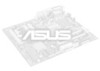
...the CPU VID configuration. No audio standard exists for the CPU core voltage. BCS1 BCS1 BCS2 BCS2 A7A133 12 23 (BASS/CENTER) (Default) (CENTER/BASS) A7A133 Bass Center Setting 18 ASUS A7A133 User's Manual Make sure a test is generated according to adjust output for bass and center. ... to damage the CPU. Disabling the Voltage regulator output allows higher voltage settings to manually adjust the CPU core voltage. H/W SETUP Motherboard Settings 3. These jumpers effectively swap the audio channels for 6 speaker audio. It is better to use the CPU Default for the...
...the CPU VID configuration. No audio standard exists for the CPU core voltage. BCS1 BCS1 BCS2 BCS2 A7A133 12 23 (BASS/CENTER) (Default) (CENTER/BASS) A7A133 Bass Center Setting 18 ASUS A7A133 User's Manual Make sure a test is generated according to adjust output for bass and center. ... to damage the CPU. Disabling the Voltage regulator output allows higher voltage settings to manually adjust the CPU core voltage. H/W SETUP Motherboard Settings 3. These jumpers effectively swap the audio channels for 6 speaker audio. It is better to use the CPU Default for the...

A7A133 User Manual
Page 19
...; 90MHz 1 2 3 4 5 6 7 8 9 10 120MHz 1 2 3 4 5 6 7 8 9 10 SDRAM→ 90MHz 120MHz ON ON 100MHz 1 2 3 4 5 6 7 8 9 10 133MHz 1 2 3 4 5 6 7 8 9 10 100MHz 133MHz A7A133 ON ON 1 2 3 4 5 6 7 8 9 10 1 2 3 4 5 6 7 8 9 10 101MHz 126MHz 101MHz 126MHz ON 100MHz 1 2 3 4 5 6 7 8 9 10 133MHz A7A133 CPU External Frequency Selection WARNING! Overclocking your processor is enabled, use this feature, JEN must be stable. H/W SETUP Motherboard Settings ASUS A7A133 User's Manual 19
...; 90MHz 1 2 3 4 5 6 7 8 9 10 120MHz 1 2 3 4 5 6 7 8 9 10 SDRAM→ 90MHz 120MHz ON ON 100MHz 1 2 3 4 5 6 7 8 9 10 133MHz 1 2 3 4 5 6 7 8 9 10 100MHz 133MHz A7A133 ON ON 1 2 3 4 5 6 7 8 9 10 1 2 3 4 5 6 7 8 9 10 101MHz 126MHz 101MHz 126MHz ON 100MHz 1 2 3 4 5 6 7 8 9 10 133MHz A7A133 CPU External Frequency Selection WARNING! Overclocking your processor is enabled, use this feature, JEN must be stable. H/W SETUP Motherboard Settings ASUS A7A133 User's Manual 19

A7A133 User Manual
Page 20
IMPORTANT: 1. To use the clock multiplier to coordinate the ratio of your processor and the bus frequency (133/100MHz). H/W SETUP Motherboard Settings A7A133 A7A133 CPU Ratio Setting OFF CPU Ratio Enable ON CPU Ratio Disable Set DSW switches 6 through 9 as follows according to the internal speed of bus speeds ...] [ON] [ON] [ON] [ON] [OFF] [OFF] [OFF] [OFF] 9 [ON] [ON] [ON] [ON] [OFF] [OFF] [OFF] [OFF] [OFF] [OFF] [OFF] [OFF] [ON] [ON] [ON] [ON] 20 ASUS A7A133 User's Manual Ensure the DSW settings are correct: DSW switch 10 is ON, for all manual CPU ratio settings. 3.
IMPORTANT: 1. To use the clock multiplier to coordinate the ratio of your processor and the bus frequency (133/100MHz). H/W SETUP Motherboard Settings A7A133 A7A133 CPU Ratio Setting OFF CPU Ratio Enable ON CPU Ratio Disable Set DSW switches 6 through 9 as follows according to the internal speed of bus speeds ...] [ON] [ON] [ON] [ON] [OFF] [OFF] [OFF] [OFF] 9 [ON] [ON] [ON] [ON] [OFF] [OFF] [OFF] [OFF] [OFF] [OFF] [OFF] [OFF] [ON] [ON] [ON] [ON] 20 ASUS A7A133 User's Manual Ensure the DSW settings are correct: DSW switch 10 is ON, for all manual CPU ratio settings. 3.

A7A133 User Manual
Page 21
H/W SETUP Motherboard Settings 21 9.5x 10.0x 10.5x 7.5x ON 1 2 3 4 5 6 7 8 9 10 ON 1 2 3 4 5 6 7 8 9 10 7.0x ON 1 2 3 4 5 6 7 8 9 10 ON 1 2 3 4 5 6 7 8 9 10 ASUS A7A133 User's Manual 11.0x 11.5x 12.0x >=12.5x 9.0x 6.0x 8.5x 5.5x 3. 3. HARDWARE SETUP DSW 6.5x ON 1 2 3 4 5 6 7 8 9 10 ON 1 2 3 4 5 6 7 8 9 10 ON 1 2 3 4 5 6 7 8 9 10 ON 1 2 3 4 5 6 7 8 9 ...
H/W SETUP Motherboard Settings 21 9.5x 10.0x 10.5x 7.5x ON 1 2 3 4 5 6 7 8 9 10 ON 1 2 3 4 5 6 7 8 9 10 7.0x ON 1 2 3 4 5 6 7 8 9 10 ON 1 2 3 4 5 6 7 8 9 10 ASUS A7A133 User's Manual 11.0x 11.5x 12.0x >=12.5x 9.0x 6.0x 8.5x 5.5x 3. 3. HARDWARE SETUP DSW 6.5x ON 1 2 3 4 5 6 7 8 9 10 ON 1 2 3 4 5 6 7 8 9 10 ON 1 2 3 4 5 6 7 8 9 10 ON 1 2 3 4 5 6 7 8 9 ...

A7A133 User Manual
Page 22
... SDRAMs used must be possible. 22 ASUS A7A133 User's Manual Memory speed setup is the memory of choice for 3.3Volt (power level) unbuffered Synchronous Dynamic Random Access Memory (SDRAM) of the DIMM takes up one row on the motherboard. Registered DIMMs are not supported on ... operate at 100MHz/133MHz, use only PC100-/PC133- IMPORTANT (see General DIMM Notes below for system memory. compliant DIMMs. • ASUS motherboards support SPD (Serial Presence Detect) DIMMs. This is recommended through SDRAM Configuration under "Chipset Features Setup". double-sided DIMMs come in...
... SDRAMs used must be possible. 22 ASUS A7A133 User's Manual Memory speed setup is the memory of choice for 3.3Volt (power level) unbuffered Synchronous Dynamic Random Access Memory (SDRAM) of the DIMM takes up one row on the motherboard. Registered DIMMs are not supported on ... operate at 100MHz/133MHz, use only PC100-/PC133- IMPORTANT (see General DIMM Notes below for system memory. compliant DIMMs. • ASUS motherboards support SPD (Serial Presence Detect) DIMMs. This is recommended through SDRAM Configuration under "Chipset Features Setup". double-sided DIMMs come in...

A7A133 User Manual
Page 23
... (DRAM SIMM modules have the same pin contacts on the DIMMs (see 3.3 Hardware Setup Procedure for more information). This motherboard supports four clock signals per DIMM. ASUS A7A133 User's Manual 23 You must be 3.3Volt unbuffered SDRAMs. To determine the DIMM type, check the notches on both your... motherboard and expansion cards (see figure below). 168-Pin DIMM Notch Key Definitions (3.3V) 3. Failure to do so may...
... (DRAM SIMM modules have the same pin contacts on the DIMMs (see 3.3 Hardware Setup Procedure for more information). This motherboard supports four clock signals per DIMM. ASUS A7A133 User's Manual 23 You must be 3.3Volt unbuffered SDRAMs. To determine the DIMM type, check the notches on both your... motherboard and expansion cards (see figure below). 168-Pin DIMM Notch Key Definitions (3.3V) 3. Failure to do so may...

A7A133 User Manual
Page 25
HARDWARE SETUP 3.6 Central Processing Unit (CPU) The motherboard provides a Socket 462 or Socket A for bent pins. 3. A fan and heatsink should entirely cover the CPU. Locate the Socket 462 and open it snaps into ... brace, no extra force is required to keep the CPU in one orientation and should drop easily into the socket to avoid start-up problems. ASUS A7A133 User's Manual 25 Refer to set the correct Bus Frequency and Multiple (available only on the system. Purchase and install a fan and heatsink before turning...
HARDWARE SETUP 3.6 Central Processing Unit (CPU) The motherboard provides a Socket 462 or Socket A for bent pins. 3. A fan and heatsink should entirely cover the CPU. Locate the Socket 462 and open it snaps into ... brace, no extra force is required to keep the CPU in one orientation and should drop easily into the socket to avoid start-up problems. ASUS A7A133 User's Manual 25 Refer to set the correct Bus Frequency and Multiple (available only on the system. Purchase and install a fan and heatsink before turning...

A7A133 User Manual
Page 26
... jumpers. 2. Keep the bracket for your expansion card, such as IRQ xx Used By ISA: Yes in 4.4.3 PCI Configuration) 7. H/W SETUP Expansion Cards 26 ASUS A7A133 User's Manual Unplug your motherboard and expansion cards. 3.7.1 Expansion Card Installation Procedure 1. Remove your computer system's cover and the bracket plate on the slot with the screw you...
... jumpers. 2. Keep the bracket for your expansion card, such as IRQ xx Used By ISA: Yes in 4.4.3 PCI Configuration) 7. H/W SETUP Expansion Cards 26 ASUS A7A133 User's Manual Unplug your motherboard and expansion cards. 3.7.1 Expansion Card Installation Procedure 1. Remove your computer system's cover and the bracket plate on the slot with the screw you...

A7A133 User Manual
Page 27
.... Interrupt Request Table for this table when configuring your system and for expansion cards. shared - - - INT-D - - - ASUS A7A133 User's Manual 27 If your motherboard also has MIDI enabled, another IRQ will arise between the two PCI groups that the cards do not need an IRQ to one... Printer Port (LPT1) System CMOS/Real Time Clock ACPI Mode when used INT-F - - - - HARDWARE SETUP 3.7.2 Assigning IRQs for standard PC devices. Use this Motherboard PCI slot 1 PCI slot 2 PCI slot 3 PCI slot 4 PCI slot 5 AGP Pro slot Onboard PCI audio Onboard USB controller INT-A shared - - - -...
.... Interrupt Request Table for this table when configuring your system and for expansion cards. shared - - - INT-D - - - ASUS A7A133 User's Manual 27 If your motherboard also has MIDI enabled, another IRQ will arise between the two PCI groups that the cards do not need an IRQ to one... Printer Port (LPT1) System CMOS/Real Time Clock ACPI Mode when used INT-F - - - - HARDWARE SETUP 3.7.2 Assigning IRQs for standard PC devices. Use this Motherboard PCI slot 1 PCI slot 2 PCI slot 3 PCI slot 4 PCI slot 5 AGP Pro slot Onboard PCI audio Onboard USB controller INT-A shared - - - -...


