
User Guide
Page 3
Contents Safety information...iv About this guide...iv Package contents...vi A58M-K specifications summary vi Product introduction 1.1 Before you proceed 1-1 1.2 Motherboard overview 1-2 1.3 Accelerated Processing Unit (APU 1-4 1.4 System memory 1-7 1.5 Expansion slots 1-10 1.6 Jumpers...1-12 1.7 Connectors 1-13 1.8 Onboard LEDs 1-... 2-9 2.4 Main menu...2-10 2.5 Ai Tweaker menu 2-11 2.6 Advanced menu 2-12 2.7 Monitor menu 2-12 2.8 Boot menu...2-13 2.9 Tools menu 2-14 2.10 Exit menu...2-14 Appendices Notices...A-1 ASUS contact information A-4 iii
Contents Safety information...iv About this guide...iv Package contents...vi A58M-K specifications summary vi Product introduction 1.1 Before you proceed 1-1 1.2 Motherboard overview 1-2 1.3 Accelerated Processing Unit (APU 1-4 1.4 System memory 1-7 1.5 Expansion slots 1-10 1.6 Jumpers...1-12 1.7 Connectors 1-13 1.8 Onboard LEDs 1-... 2-9 2.4 Main menu...2-10 2.5 Ai Tweaker menu 2-11 2.6 Advanced menu 2-12 2.7 Monitor menu 2-12 2.8 Boot menu...2-13 2.9 Tools menu 2-14 2.10 Exit menu...2-14 Appendices Notices...A-1 ASUS contact information A-4 iii
User Guide
Page 6
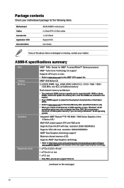
... AMD® Dual Graphics technology support* Maximum shared memory of the above DIMMs. ASUS will update the memory QVL once the DIMMs are using a Windows® 32-bit operating system. A58M-K specifications summary APU Chipset Memory Graphics Expansion slots AMD® FM2+ Socket for ... http://www.amd.com/us/products/technologies/dual-graphics/Pages/ dual-graphics.aspx#3 for the following items. Motherboard Cables Accessories Application DVD Documentation ASUS A58M-K motherboard 2 x Serial ATA 3.0 Gb/s cables 1 x I/O Shield Support DVD User Guide If any of 2G Supports AMD® Dual ...
... AMD® Dual Graphics technology support* Maximum shared memory of the above DIMMs. ASUS will update the memory QVL once the DIMMs are using a Windows® 32-bit operating system. A58M-K specifications summary APU Chipset Memory Graphics Expansion slots AMD® FM2+ Socket for ... http://www.amd.com/us/products/technologies/dual-graphics/Pages/ dual-graphics.aspx#3 for the following items. Motherboard Cables Accessories Application DVD Documentation ASUS A58M-K motherboard 2 x Serial ATA 3.0 Gb/s cables 1 x I/O Shield Support DVD User Guide If any of 2G Supports AMD® Dual ...
User Guide
Page 7
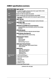
A58M-K specifications summary Storage / RAID LAN Audio USB ASUS unique features Back Panel I /O ports (3-jack) (continued on the next page) vii ASUS EPU - ASUS UEFI BIOS EZ Mode - AMD® A58 FCH - 8 x USB 2.0 ports (4 ports at the back panel, 4 ports at mid-board) ASUS DIGI+ VRM - 3+1 Phase digital power design ASUS Enhanced DRAM Overcurrent Protection - Enhanced DRAM...
A58M-K specifications summary Storage / RAID LAN Audio USB ASUS unique features Back Panel I /O ports (3-jack) (continued on the next page) vii ASUS EPU - ASUS UEFI BIOS EZ Mode - AMD® A58 FCH - 8 x USB 2.0 ports (4 ports at the back panel, 4 ports at mid-board) ASUS DIGI+ VRM - 3+1 Phase digital power design ASUS Enhanced DRAM Overcurrent Protection - Enhanced DRAM...

User Guide
Page 9
... as the power supply case, to avoid damaging them due to static electricity. • Hold components by the edges to the motherboard, peripherals, or components. ASUS A58M-K 1-1
... as the power supply case, to avoid damaging them due to static electricity. • Hold components by the edges to the motherboard, peripherals, or components. ASUS A58M-K 1-1

User Guide
Page 11
... 12. Front panel audio connector (10-1 pin AAFP) Page 1-15 1-4 1-14 1-7 1-17 1-16 1-17 1-19 1-12 1-18 1-15 1-16 1-19 1-18 ASUS A58M-K 1-3 Clear RTC RAM (3-pin CLRTC) 10. 1.2.3 Motherboard layout 1 2 3 4 18.3cm(7.2in) KBMS ATX12V DIGI +VRM CPU_FAN CHA_FAN DDR3 DIMM_A1 (64bit, 240-pin... module) DDR3 DIMM_B1 (64bit, 240-pin module) SOCKET FM2+ DVI_VGA 22.6cm(8.9in) USB1112 EATXPWR LAN_USB12 1 AUDIO 8111 GR A58M-K PCIEX16 Super I/O SB_PWR PCIEX1_1 BATTERY AMD® 5 A58 SPEAKER SATA3G_4 ALC 887 PCI1 F_PANEL 6 SPDIF_OUT 64Mb BIOS 7 TPM USB56 USB34 ...
... 12. Front panel audio connector (10-1 pin AAFP) Page 1-15 1-4 1-14 1-7 1-17 1-16 1-17 1-19 1-12 1-18 1-15 1-16 1-19 1-18 ASUS A58M-K 1-3 Clear RTC RAM (3-pin CLRTC) 10. 1.2.3 Motherboard layout 1 2 3 4 18.3cm(7.2in) KBMS ATX12V DIGI +VRM CPU_FAN CHA_FAN DDR3 DIMM_A1 (64bit, 240-pin... module) DDR3 DIMM_B1 (64bit, 240-pin module) SOCKET FM2+ DVI_VGA 22.6cm(8.9in) USB1112 EATXPWR LAN_USB12 1 AUDIO 8111 GR A58M-K PCIEX16 Super I/O SB_PWR PCIEX1_1 BATTERY AMD® 5 A58 SPEAKER SATA3G_4 ALC 887 PCI1 F_PANEL 6 SPDIF_OUT 64Mb BIOS 7 TPM USB56 USB34 ...

User Guide
Page 13
To install the APU heatsink and fan assembly 1 2 ASUS A58M-K 1-5 3 4 1.3.2 APU heatsink and fan assembly installation Apply the Thermal Interface Material to the APU heatsink and APU before you install the heatsink and fan if necessary.
To install the APU heatsink and fan assembly 1 2 ASUS A58M-K 1-5 3 4 1.3.2 APU heatsink and fan assembly installation Apply the Thermal Interface Material to the APU heatsink and APU before you install the heatsink and fan if necessary.

User Guide
Page 15
DDR3 modules are developed for better performance with two Double Data Rate 3 (DDR3) Dual Inline Memory Modules (DIMM) sockets. The figure illustrates the location of the DDR3 DIMM sockets: DIMM_A1 DIMM_B1 A58M-K A58M-K 240-pin DDR3 DIMM sockets Channel Channel A Channel B Sockets DIMM_A1 DIMM_B1 ASUS A58M-K 1-7 1.4 System memory 1.4.1 Overview The motherboard comes with less power consumption. A DDR3 module has the same physical dimensions as a DDR2 DIMM but is notched differently to prevent installation on a DDR2 DIMM socket.
DDR3 modules are developed for better performance with two Double Data Rate 3 (DDR3) Dual Inline Memory Modules (DIMM) sockets. The figure illustrates the location of the DDR3 DIMM sockets: DIMM_A1 DIMM_B1 A58M-K A58M-K 240-pin DDR3 DIMM sockets Channel Channel A Channel B Sockets DIMM_A1 DIMM_B1 ASUS A58M-K 1-7 1.4 System memory 1.4.1 Overview The motherboard comes with less power consumption. A DDR3 module has the same physical dimensions as a DDR2 DIMM but is notched differently to prevent installation on a DDR2 DIMM socket.

User Guide
Page 17
1.4.3 1 Installing a DIMM 2 3 To remove a DIMM B A ASUS A58M-K 1-9
1.4.3 1 Installing a DIMM 2 3 To remove a DIMM B A ASUS A58M-K 1-9

User Guide
Page 19
Realtek LAN controller - - On Chip USB OHCI 1/2/3/4 - - ASUS A58M-K 1-11 On Chip USB EHCI 1/2/3 - shared - - - - - - PCI1 slot - - - - HD audio shared - - - - - - - shared - - - - - 1.5.4 PCI Express x1 slot This motherboard supports PCI Express 2.0 x1 network cards, SCSI ...
Realtek LAN controller - - On Chip USB OHCI 1/2/3/4 - - ASUS A58M-K 1-11 On Chip USB EHCI 1/2/3 - shared - - - - - - PCI1 slot - - - - HD audio shared - - - - - - - shared - - - - - 1.5.4 PCI Express x1 slot This motherboard supports PCI Express 2.0 x1 network cards, SCSI ...

User Guide
Page 21
... the tape, CD, DVD player, or other VGA-compatible devices. 3. In the 4.1, 5.1, and 7.1-channel configurations, the function of the audio ports in 2.1, 4.1, 5.1, or 7.1-channel configuration. ASUS A58M-K 1-13 This port is for the function of this port becomes Front Speaker Out. 6. Video Graphics Adapter (VGA) port. This port allows Gigabit connection to...
... the tape, CD, DVD player, or other VGA-compatible devices. 3. In the 4.1, 5.1, and 7.1-channel configurations, the function of the audio ports in 2.1, 4.1, 5.1, or 7.1-channel configuration. ASUS A58M-K 1-13 This port is for the function of this port becomes Front Speaker Out. 6. Video Graphics Adapter (VGA) port. This port allows Gigabit connection to...

User Guide
Page 23
...when you intend to use a PSU with 20-pin and 4-pin power plugs, ensure that the 20-pin power plug can provide at http://support.asus. The plugs from the power supply are designed to connect the 4-pin ATX +12V power plug. com/PowerSupplyCalculator/PSCalculator.aspx?SLanguage=en-us for ... connectors GND +5 Volts +5 Volts +5 Volts -5 Volts GND GND GND PSON# GND -12 Volts +3 Volts • We recommend that you are for details. 3. ASUS A58M-K 1-15 The system may become unstable or may not boot up if the power is inadequate. • If you use a PSU with higher power output ...
...when you intend to use a PSU with 20-pin and 4-pin power plugs, ensure that the 20-pin power plug can provide at http://support.asus. The plugs from the power supply are designed to connect the 4-pin ATX +12V power plug. com/PowerSupplyCalculator/PSCalculator.aspx?SLanguage=en-us for ... connectors GND +5 Volts +5 Volts +5 Volts -5 Volts GND GND GND PSON# GND -12 Volts +3 Volts • We recommend that you are for details. 3. ASUS A58M-K 1-15 The system may become unstable or may not boot up if the power is inadequate. • If you use a PSU with higher power output ...

User Guide
Page 25
... button (2-pin RESET) This 2-pin connector is for system reboot without turning off the system power. 7. Ground HWRST# (NC) A58M-K PIN 1 +HDD_LED RESET A58M-K System panel connector • System power LED (2-pin PWR_LED) This 2-pin connector is for the system power LED. F_PANEL +PWR... connector. Connect the HDD Activity LED cable to hear system beeps and warnings. +5V GND GND Speaker Out SPEAKER A58M-K PIN 1 A58M-K Speaker Out Connector ASUS A58M-K 1-17 Speaker connector (4-pin SPEAKER) The 4-pin connector is for the chassis-mounted reset button for the chassis-mounted...
... button (2-pin RESET) This 2-pin connector is for system reboot without turning off the system power. 7. Ground HWRST# (NC) A58M-K PIN 1 +HDD_LED RESET A58M-K System panel connector • System power LED (2-pin PWR_LED) This 2-pin connector is for the system power LED. F_PANEL +PWR... connector. Connect the HDD Activity LED cable to hear system beeps and warnings. +5V GND GND Speaker Out SPEAKER A58M-K PIN 1 A58M-K Speaker Out Connector ASUS A58M-K 1-17 Speaker connector (4-pin SPEAKER) The 4-pin connector is for the chassis-mounted reset button for the chassis-mounted...

User Guide
Page 27
... Doing so will damage the motherboard! USB56 USB34 USB+5V USB_P5USB_P5+ GND NC USB+5V USB_P3USB_P3+ GND NC A58M-K PIN 1 PIN 1 USB+5V USB_P6USB_P6+ GND USB+5V USB_P4USB_P4+ GND A58M-K USB2.0 connectors Never connect a 1394 cable to 480Mbps connection speed. Connect the USB module cable to a slot...comply with a standby power LED that lights up to indicate that supports up to the USB connectors. 10. SB_PWR A58M-K ON OFF Standby Power Powered Off A58M-K Onboard LED ASUS A58M-K 1-19 The USB 2.0 module is ON, in sleep mode, or in any of these connectors, then install ...
... Doing so will damage the motherboard! USB56 USB34 USB+5V USB_P5USB_P5+ GND NC USB+5V USB_P3USB_P3+ GND NC A58M-K PIN 1 PIN 1 USB+5V USB_P6USB_P6+ GND USB+5V USB_P4USB_P4+ GND A58M-K USB2.0 connectors Never connect a 1394 cable to 480Mbps connection speed. Connect the USB module cable to a slot...comply with a standby power LED that lights up to indicate that supports up to the USB connectors. 10. SB_PWR A58M-K ON OFF Standby Power Powered Off A58M-K Onboard LED ASUS A58M-K 1-19 The USB 2.0 module is ON, in sleep mode, or in any of these connectors, then install ...
User Guide
Page 29
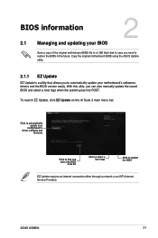
... a copy of the original motherboard BIOS file to a USB flash disk in case you need to restore the BIOS in the future. ASUS A58M-K 2-1 Copy the original motherboard BIOS using the ASUS Update utility. 2.1.1 EZ Update EZ Update is a utility that allows you can also manually update the saved BIOS and select a boot...
... a copy of the original motherboard BIOS file to a USB flash disk in case you need to restore the BIOS in the future. ASUS A58M-K 2-1 Copy the original motherboard BIOS using the ASUS Update utility. 2.1.1 EZ Update EZ Update is a utility that allows you can also manually update the saved BIOS and select a boot...
User Guide
Page 31
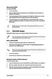
...reference only and may not be exactly the same as the boot device. To ensure system compatibility and stability, we recommend that your computer screen. ASUS A58M-K 2-3 Recovering the BIOS To recover the BIOS: 1. DO NOT shut down or reset the system while updating the BIOS! Doing so can ...cause system boot failure! 2.1.4 ASUS BIOS Updater ASUS BIOS Updater allows you to enter BIOS Setup to update the BIOS in DOS environment. Before updating BIOS • Prepare the motherboard support ...
...reference only and may not be exactly the same as the boot device. To ensure system compatibility and stability, we recommend that your computer screen. ASUS A58M-K 2-3 Recovering the BIOS To recover the BIOS: 1. DO NOT shut down or reset the system while updating the BIOS! Doing so can ...cause system boot failure! 2.1.4 ASUS BIOS Updater ASUS BIOS Updater allows you to enter BIOS Setup to update the BIOS in DOS environment. Before updating BIOS • Prepare the motherboard support ...
User Guide
Page 33
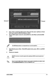
... is done, press to confirm the BIOS update. DO NOT shut down or reset the system while updating the BIOS to security regulations. 5. ASUS A58M-K 2-5 Ensure to load the BIOS default settings to update the BIOS? Are you sure you want to ensure system compatibility and stability. Drives ...panel ASUSTeK BIOS Updater for DOS V1.30 [2014/01/01] Current ROM BOARD: A58M-K VER: 0210 (H :00 B :00) DATE: 02/12/2014 PATH: C:\ Update ROM BOARD: Unknown VER: Unknown DATE: Unknown C: FORMAN~1 D: A58MK .CAP 8390626 ...
... is done, press to confirm the BIOS update. DO NOT shut down or reset the system while updating the BIOS to security regulations. 5. ASUS A58M-K 2-5 Ensure to load the BIOS default settings to update the BIOS? Are you sure you want to ensure system compatibility and stability. Drives ...panel ASUSTeK BIOS Updater for DOS V1.30 [2014/01/01] Current ROM BOARD: A58M-K VER: 0210 (H :00 B :00) DATE: 02/12/2014 PATH: C:\ Update ROM BOARD: Unknown VER: Unknown DATE: Unknown C: FORMAN~1 D: A58MK .CAP 8390626 ...

User Guide
Page 35
... the boot device is installed to select the display language, system performance mode and boot device priority. The default screen for the advanced BIOS settings. ASUS A58M-K 2-7 The EZ Mode provides you an overview of the selected mode on the right hand side • The boot device options vary depending on the...
... the boot device is installed to select the display language, system performance mode and boot device priority. The default screen for the advanced BIOS settings. ASUS A58M-K 2-7 The EZ Mode provides you an overview of the selected mode on the right hand side • The boot device options vary depending on the...

User Guide
Page 37
... submenu options • User-configurable items such as language and boot device order • Configuration items such as Memory SPD Information, system time and date ASUS A58M-K 2-9 You cannot add the following items to My Favorites page. 2.3 My Favorites MyFavorites is your personal space where you want to add. When using a mouse...
... submenu options • User-configurable items such as language and boot device order • Configuration items such as Memory SPD Information, system time and date ASUS A58M-K 2-9 You cannot add the following items to My Favorites page. 2.3 My Favorites MyFavorites is your personal space where you want to add. When using a mouse...

User Guide
Page 39
Scroll down to malfunction. 2.5 Ai Tweaker menu The Ai Tweaker menu items allow you installed on the CPU and DIMM model you to configure overclocking-related items. Be cautious when changing the settings of the Ai Tweaker menu items. Incorrect field values can cause the system to display the other items. ASUS A58M-K 2-11 The configuration options for this section vary depending on the motherboard.
Scroll down to malfunction. 2.5 Ai Tweaker menu The Ai Tweaker menu items allow you installed on the CPU and DIMM model you to configure overclocking-related items. Be cautious when changing the settings of the Ai Tweaker menu items. Incorrect field values can cause the system to display the other items. ASUS A58M-K 2-11 The configuration options for this section vary depending on the motherboard.

User Guide
Page 41
Scroll down to change the system boot options. 2.8 Boot menu The Boot menu items allow you to display the other items. ASUS A58M-K 2-13
Scroll down to change the system boot options. 2.8 Boot menu The Boot menu items allow you to display the other items. ASUS A58M-K 2-13


