
User Guide
Page 7
... vii AMD® A58 FCH: - 8 x USB 2.0/1.1 ports (4 ports at the mid-board, 4 ports at the back panel) ASUS 5X Protection - ASUS motherboards safeguard your PC with 5X Protection: DIGI+VRM, DRAM Fuse, ESD Guards, High-Quality 5K-Hour Solid Capacitors, and Stainless Steel... Back I /O - 3x More durable corrosion-resistant coating ASUS Exclusive Features - Enhanced DRAM overcurrent protection and short circuit damage prevention ASUS ESD Guards - AI Suite 3 - A58M-E specifications summary Storage / RAID LAN Audio USB ASUS unique features AMD® A58 FCH: - 6 x Serial ATA...
... vii AMD® A58 FCH: - 8 x USB 2.0/1.1 ports (4 ports at the mid-board, 4 ports at the back panel) ASUS 5X Protection - ASUS motherboards safeguard your PC with 5X Protection: DIGI+VRM, DRAM Fuse, ESD Guards, High-Quality 5K-Hour Solid Capacitors, and Stainless Steel... Back I /O - 3x More durable corrosion-resistant coating ASUS Exclusive Features - Enhanced DRAM overcurrent protection and short circuit damage prevention ASUS ESD Guards - AI Suite 3 - A58M-E specifications summary Storage / RAID LAN Audio USB ASUS unique features AMD® A58 FCH: - 6 x Serial ATA...

User Guide
Page 8
viii A58M-E specifications summary Back Panel I/O ports Internal I/O connectors BIOS Support DVD Operating System Support Form factor 1 x PS/2 mouse port (green) 1 x PS/2 keyboard port (purple) 1 x DVI-D port 1 x D-Sub output port 1 x ... x S/PDIF output connector 1 x 4-pin Chassis fan connector 1 x High Definition Front panel audio connector 1 x 24-pin EATX power connector 1 x 4-pin ATX 12V power connector 64 Mb Flash ROM, UEFI AMI BIOS, PnP, DMI 2.0, WfM 2.0, SM BIOS v2.6, ACPI 2.0a Drivers ASUS Update ASUS utilities Anti-Virus software (OEM version) Windows® 8.1 / Windows® 8.1 64...
viii A58M-E specifications summary Back Panel I/O ports Internal I/O connectors BIOS Support DVD Operating System Support Form factor 1 x PS/2 mouse port (green) 1 x PS/2 keyboard port (purple) 1 x DVI-D port 1 x D-Sub output port 1 x ... x S/PDIF output connector 1 x 4-pin Chassis fan connector 1 x High Definition Front panel audio connector 1 x 24-pin EATX power connector 1 x 4-pin ATX 12V power connector 64 Mb Flash ROM, UEFI AMI BIOS, PnP, DMI 2.0, WfM 2.0, SM BIOS v2.6, ACPI 2.0a Drivers ASUS Update ASUS utilities Anti-Virus software (OEM version) Windows® 8.1 / Windows® 8.1 64...
User Guide
Page 11
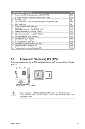
...pins and damaging the APU! SATA 3.0Gb/s connectors (7-pin SATA3G_1~6) 8. Serial port connector (10-1 pin COM) 15. System panel connector (10-1 pin F_PANEL) 9. TPM connector (20-1 pin TPM) 13. Keyboard and USB device wake up (3-pin USBPWF)... 11. AMD FM2+ socket 4. Clear RTC RAM (3-pin CLRTC) 12. USB 2.0 connectors (10-1 pin USB34, USB56) 10. Front panel audio connector (10-1 pin AAFP) Page 1-12 1-15 1-3 1-14 1-6 1-18 1-16 1-17 1-19 1-11 1-10 1-14 1-16 1-...4-pin ATX12V) 3. Speaker connector (4-pin SPEAKER) 7. USB device wake-up (3-pin KB_USBPWB) 2. ASUS A58M-E 1-3
...pins and damaging the APU! SATA 3.0Gb/s connectors (7-pin SATA3G_1~6) 8. Serial port connector (10-1 pin COM) 15. System panel connector (10-1 pin F_PANEL) 9. TPM connector (20-1 pin TPM) 13. Keyboard and USB device wake up (3-pin USBPWF)... 11. AMD FM2+ socket 4. Clear RTC RAM (3-pin CLRTC) 12. USB 2.0 connectors (10-1 pin USB34, USB56) 10. Front panel audio connector (10-1 pin AAFP) Page 1-12 1-15 1-3 1-14 1-6 1-18 1-16 1-17 1-19 1-11 1-10 1-14 1-16 1-...4-pin ATX12V) 3. Speaker connector (4-pin SPEAKER) 7. USB device wake-up (3-pin KB_USBPWB) 2. ASUS A58M-E 1-3

User Guide
Page 20
... and USB device wake up (3-pin KB_USBPWB) This jumper allows you can supply at least 1A on the keyboard. KB_USBPWB 12 23 A58M-E +5V +5VSB (Default) A58M-E Keyboard and USB device wake up the computer by pressing a key on the +5VSB lead, and a corresponding setting in the ...BIOS. This 15-pin port is for a VGA monitor or other VGA-compatible devices. 3. This feature requires an ATX power supply that can wake up 1.7 1.7.1 1 Connectors Rear panel...
... and USB device wake up (3-pin KB_USBPWB) This jumper allows you can supply at least 1A on the keyboard. KB_USBPWB 12 23 A58M-E +5V +5VSB (Default) A58M-E Keyboard and USB device wake up the computer by pressing a key on the +5VSB lead, and a corresponding setting in the ...BIOS. This 15-pin port is for a VGA monitor or other VGA-compatible devices. 3. This feature requires an ATX power supply that can wake up 1.7 1.7.1 1 Connectors Rear panel...

User Guide
Page 21
... LED LAN port 4. USB 2.0 ports 11 and 12. ASUS A58M-E 1-13 In the 4.1, 5.1, and 7.1-channel configurations, the function of the audio ports in the front panel to support a 7.1-channel audio output. 7. Audio 2.1, 4.1, 5.1, or 7.1-channel configuration Port Light Blue (Rear panel) Lime (Rear panel) Pink (Rear panel) Lime (Front panel) Headset 2.1- This port is for USB 2.0/1.1 devices. 9. This...
... LED LAN port 4. USB 2.0 ports 11 and 12. ASUS A58M-E 1-13 In the 4.1, 5.1, and 7.1-channel configurations, the function of the audio ports in the front panel to support a 7.1-channel audio output. 7. Audio 2.1, 4.1, 5.1, or 7.1-channel configuration Port Light Blue (Rear panel) Lime (Rear panel) Pink (Rear panel) Lime (Front panel) Headset 2.1- This port is for USB 2.0/1.1 devices. 9. This...
User Guide
Page 25
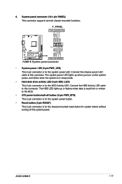
Ground HWRST# (NC) A58M-E PIN 1 +HDD_LED RESET A58M-E System panel connector • System power LED (2-pin PWR_LED) This 2-pin connector is for the HDD Activity LED. System panel connector (10-1 pin PANEL) This connector supports several chassis-mounted functions. Connect the HDD Activity LED cable to this connector. The system .... • Reset button (2-pin RESET) This 2-pin connector is for the chassis-mounted reset button for the system power LED. 6. ASUS A58M-E 1-17 Connect the chassis power LED cable to the HDD. • ATX power button/soft-off the system power.
Ground HWRST# (NC) A58M-E PIN 1 +HDD_LED RESET A58M-E System panel connector • System power LED (2-pin PWR_LED) This 2-pin connector is for the HDD Activity LED. System panel connector (10-1 pin PANEL) This connector supports several chassis-mounted functions. Connect the HDD Activity LED cable to this connector. The system .... • Reset button (2-pin RESET) This 2-pin connector is for the chassis-mounted reset button for the system power LED. 6. ASUS A58M-E 1-17 Connect the chassis power LED cable to the HDD. • ATX power button/soft-off the system power.
User Guide
Page 26
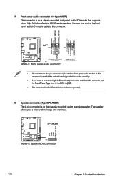
... NC AAFP PIN 1 PIN 1 MIC2 MICPWR Line out_R NC Line out_L PORT1 L PORT1 R PORT2 R SENSE_SEND PORT2 L A58M-E HD-audio-compliant pin definition A58M-E Front panel audio connector Legacy ACʼ97 compliant definition • We recommend that supports either High Definition Audio or AC`97 audio ... audio capability. • If you to this connector, set the Front Panel Type item in the BIOS to [HD]. • The front panel audio I /O module cable to hear system beeps and warnings. SPEAKER A58M-E PIN 1 A58M-E Speaker Out Connector +5V GND GND Speaker Out 1-18 Chapter 1: Product...
... NC AAFP PIN 1 PIN 1 MIC2 MICPWR Line out_R NC Line out_L PORT1 L PORT1 R PORT2 R SENSE_SEND PORT2 L A58M-E HD-audio-compliant pin definition A58M-E Front panel audio connector Legacy ACʼ97 compliant definition • We recommend that supports either High Definition Audio or AC`97 audio ... audio capability. • If you to this connector, set the Front Panel Type item in the BIOS to [HD]. • The front panel audio I /O module cable to hear system beeps and warnings. SPEAKER A58M-E PIN 1 A58M-E Speaker Out Connector +5V GND GND Speaker Out 1-18 Chapter 1: Product...


