
User Guide
Page 2
... DEFECT OR ERROR IN THIS MANUAL OR PRODUCT. Copies of these licenses are used only for backup purposes, without the express written permission of this email address). Where the applicable license entitles you to anyone in writing by the applicable law. No part of such software and/or other Free Open Source Software Licenses. ASUS PROVIDES THIS MANUAL "AS IS...
... DEFECT OR ERROR IN THIS MANUAL OR PRODUCT. Copies of these licenses are used only for backup purposes, without the express written permission of this email address). Where the applicable license entitles you to anyone in writing by the applicable law. No part of such software and/or other Free Open Source Software Licenses. ASUS PROVIDES THIS MANUAL "AS IS...

User Guide
Page 4
... retailer. Operation safety • Before installing the motherboard and adding devices on a stable surface. • If you need when installing and configuring the motherboard. How this guide This user guide contains the information you encounter technical problems with the package. • Before using the product, ensure all power cables from connectors, slots, sockets and circuitry. • Avoid dust, humidity, and temperature extremes. Safety information Electrical safety •...
... retailer. Operation safety • Before installing the motherboard and adding devices on a stable surface. • If you need when installing and configuring the motherboard. How this guide This user guide contains the information you encounter technical problems with the package. • Before using the product, ensure all power cables from connectors, slots, sockets and circuitry. • Avoid dust, humidity, and temperature extremes. Safety information Electrical safety •...
User Guide
Page 6
...Application DVD Documentation ASUS A58M-E motherboard 2 x Serial ATA 3.0 Gb/s cables 1 x I/O Shield Support DVD User Guide If any of 3GB system memory if you install a total memory of 2G Supports AMD® Dual Graphics technology * Refer to http://www.amd.com/us/products/technologies/dual-graphics/ Pages/dual-graphics.aspx#3 for the AMD® CPU support list. A58M-E specifications summary CPU Chipset Memory Graphics Expansion slots AMD® FM2+ Socket for AMD® A-Series/Athlon™ Series processors AMD® Turbo Core Technology 3.0 support Supports APU up to 4 cores •...
...Application DVD Documentation ASUS A58M-E motherboard 2 x Serial ATA 3.0 Gb/s cables 1 x I/O Shield Support DVD User Guide If any of 3GB system memory if you install a total memory of 2G Supports AMD® Dual Graphics technology * Refer to http://www.amd.com/us/products/technologies/dual-graphics/ Pages/dual-graphics.aspx#3 for the AMD® CPU support list. A58M-E specifications summary CPU Chipset Memory Graphics Expansion slots AMD® FM2+ Socket for AMD® A-Series/Athlon™ Series processors AMD® Turbo Core Technology 3.0 support Supports APU up to 4 cores •...
User Guide
Page 7
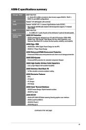
... - ASUS Fan Xpert ASUS EZ DIY - ASUS CrashFree BIOS 3 - AI Charger - EPU - ASUS 3+1 Phase Power Design ASUS Enhanced DRAM Overcurrent Protection - ASUS Fanless Design: Stylish heatsink solution - ASUS MyLogo 2 (continued on the next page) vii A58M-E specifications summary Storage / RAID LAN Audio USB ASUS unique features AMD® A58 FCH: - 6 x Serial ATA 3.0Gb/s connectors (dark brown) support RAID 0, RAID 1, RAID 10, and JBOD configurations Realtek® 8111GR Gigabit LAN controller Realtek® ALC887-VD 7.1-channel High Definition Audio CODEC • Use a chassis...
... - ASUS Fan Xpert ASUS EZ DIY - ASUS CrashFree BIOS 3 - AI Charger - EPU - ASUS 3+1 Phase Power Design ASUS Enhanced DRAM Overcurrent Protection - ASUS Fanless Design: Stylish heatsink solution - ASUS MyLogo 2 (continued on the next page) vii A58M-E specifications summary Storage / RAID LAN Audio USB ASUS unique features AMD® A58 FCH: - 6 x Serial ATA 3.0Gb/s connectors (dark brown) support RAID 0, RAID 1, RAID 10, and JBOD configurations Realtek® 8111GR Gigabit LAN controller Realtek® ALC887-VD 7.1-channel High Definition Audio CODEC • Use a chassis...

User Guide
Page 8
...x USB 2.0 connectors support additional 4 USB 2.0 ports 6 x SATA 3.0Gb/s connectors 1 x COM connector 1 x TPM header 1 x System panel connector 1 x Internal Speaker connector 1 x 4-pin CPU fan connector 1 x S/PDIF output connector 1 x 4-pin Chassis fan connector 1 x High Definition Front panel audio connector 1 x 24-pin EATX power connector 1 x 4-pin ATX 12V power connector 64 Mb Flash ROM, UEFI AMI BIOS, PnP, DMI 2.0, WfM 2.0, SM BIOS v2.6, ACPI 2.0a Drivers ASUS Update ASUS utilities Anti-Virus software (OEM version) Windows® 8.1 / Windows® 8.1 64-bit Windows® 8 / Windows®...
...x USB 2.0 connectors support additional 4 USB 2.0 ports 6 x SATA 3.0Gb/s connectors 1 x COM connector 1 x TPM header 1 x System panel connector 1 x Internal Speaker connector 1 x 4-pin CPU fan connector 1 x S/PDIF output connector 1 x 4-pin Chassis fan connector 1 x High Definition Front panel audio connector 1 x 24-pin EATX power connector 1 x 4-pin ATX 12V power connector 64 Mb Flash ROM, UEFI AMI BIOS, PnP, DMI 2.0, WfM 2.0, SM BIOS v2.6, ACPI 2.0a Drivers ASUS Update ASUS utilities Anti-Virus software (OEM version) Windows® 8.1 / Windows® 8.1 64-bit Windows® 8 / Windows®...

User Guide
Page 9
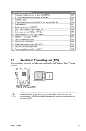
... or change any motherboard settings. • Unplug the power cord from the wall socket before installing or removing the motherboard. Failure to ensure that the ATX power supply is switched off or the power cord is detached from the power supply. Do not overtighten the screws! Failure to do so may cause severe damage to the motherboard, peripherals, or components. 1.2 Motherboard overview Before you install the motherboard, study the configuration of your chassis...
... or change any motherboard settings. • Unplug the power cord from the wall socket before installing or removing the motherboard. Failure to ensure that the ATX power supply is switched off or the power cord is detached from the power supply. Do not overtighten the screws! Failure to do so may cause severe damage to the motherboard, peripherals, or components. 1.2 Motherboard overview Before you install the motherboard, study the configuration of your chassis...
User Guide
Page 11
...+ socket. System panel connector (10-1 pin F_PANEL) 9. Keyboard and USB device wake up (3-pin USBPWF) 11. CPU and chassis fan connectors (4-pin CPU_FAN and 4-pin CHA_FAN) 5. A58M-E A58M-E CPU socket FM2+ Ensure that you use an APU designed for AMD® A-series / Athlon™ Series graphics. USB device wake-up (3-pin KB_USBPWB) 2. DO NOT force the APU into the socket to prevent bending the pins and damaging the APU! DDR3 DIMM slots 6. ASUS A58M-E 1-3 SATA 3.0Gb/s connectors (7-pin SATA3G_1~6) 8. Speaker connector (4-pin SPEAKER) 7. Serial port connector (10-1 pin...
...+ socket. System panel connector (10-1 pin F_PANEL) 9. Keyboard and USB device wake up (3-pin USBPWF) 11. CPU and chassis fan connectors (4-pin CPU_FAN and 4-pin CHA_FAN) 5. A58M-E A58M-E CPU socket FM2+ Ensure that you use an APU designed for AMD® A-series / Athlon™ Series graphics. USB device wake-up (3-pin KB_USBPWB) 2. DO NOT force the APU into the socket to prevent bending the pins and damaging the APU! DDR3 DIMM slots 6. ASUS A58M-E 1-3 SATA 3.0Gb/s connectors (7-pin SATA3G_1~6) 8. Speaker connector (4-pin SPEAKER) 7. Serial port connector (10-1 pin...

User Guide
Page 15
... less. Install a maximum of accessing information from a memory module. Under the default state, some memory modules for overclocking may install varying memory sizes in the market. • The default memory operation frequency is dependent on the motherboard. • This motherboard does not support DIMMs made up of the following: - For optimal compatibility, we recommend that you install memory modules of the same version or date code (D/C) from the higher-sized channel is...
... less. Install a maximum of accessing information from a memory module. Under the default state, some memory modules for overclocking may install varying memory sizes in the market. • The default memory operation frequency is dependent on the motherboard. • This motherboard does not support DIMMs made up of the following: - For optimal compatibility, we recommend that you install memory modules of the same version or date code (D/C) from the higher-sized channel is...
User Guide
Page 17
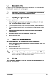
... the card inoperable. 1.5.3 PCI slot The PCI slot supports cards such as a LAN card, SCSI card, USB card, and other cards that you physical injury and damage motherboard components. 1.5.1 Installing an expansion card To install an expansion card: 1. Remove the system unit cover (if your motherboard is completely seated on BIOS setup. 2. Replace the system cover. 1.5.2 Configuring an expansion card After installing the expansion card, configure it and make the necessary hardware settings for later use . ASUS A58M-E 1-9 Secure the card to use . 4. The...
... the card inoperable. 1.5.3 PCI slot The PCI slot supports cards such as a LAN card, SCSI card, USB card, and other cards that you physical injury and damage motherboard components. 1.5.1 Installing an expansion card To install an expansion card: 1. Remove the system unit cover (if your motherboard is completely seated on BIOS setup. 2. Replace the system cover. 1.5.2 Configuring an expansion card After installing the expansion card, configure it and make the necessary hardware settings for later use . ASUS A58M-E 1-9 Secure the card to use . 4. The...

User Guide
Page 18
... Jumpers Clear RTC RAM (3-pin CLRTC) This jumper allows you to clear the Real Time Clock (RTC) RAM in CMOS, which include system setup information such as system passwords. You can clear the CMOS memory of date, time, and system setup parameters by erasing the CMOS RTC RAM data. IRQ assignments for this motherboard A B C D E F G H PCIEx16_1 - - HD audio shared - - - - - - - shared - - - - - The onboard button cell battery powers the RAM data in CMOS. SATA controller - - - 1.5.4 PCI Express x1 slot This motherboard supports PCI Express 2.0 x1 network cards...
... Jumpers Clear RTC RAM (3-pin CLRTC) This jumper allows you to clear the Real Time Clock (RTC) RAM in CMOS, which include system setup information such as system passwords. You can clear the CMOS memory of date, time, and system setup parameters by erasing the CMOS RTC RAM data. IRQ assignments for this motherboard A B C D E F G H PCIEx16_1 - - HD audio shared - - - - - - - shared - - - - - The onboard button cell battery powers the RAM data in CMOS. SATA controller - - - 1.5.4 PCI Express x1 slot This motherboard supports PCI Express 2.0 x1 network cards...

User Guide
Page 19
... jumper again to pins 2-3. Shut down the key during the boot process and enter BIOS setup to wake up . • The total current consumed must NOT exceed the power supply capability (+5VSB) whether under normal condition or in low power mode) using the connected USB devices. ASUS A58M-E 1-11 A58M-E USBPWF 12 23 +5V +5VSB (Default) A58M-E USB device wake up • The USB device wake-up from pins 1-2 (default) to clear the CMOS RTC RAM data. enter data. For system failure due to default...
... jumper again to pins 2-3. Shut down the key during the boot process and enter BIOS setup to wake up . • The total current consumed must NOT exceed the power supply capability (+5VSB) whether under normal condition or in low power mode) using the connected USB devices. ASUS A58M-E 1-11 A58M-E USBPWF 12 23 +5V +5VSB (Default) A58M-E USB device wake up • The USB device wake-up from pins 1-2 (default) to clear the CMOS RTC RAM data. enter data. For system failure due to default...

User Guide
Page 20
... enable or disable the keyboard and USB device wake-up the computer by pressing a key on the +5VSB lead, and a corresponding setting in the BIOS. LAN (RJ-45) port. This feature requires an ATX power supply that can wake up feature. PS/2 Mouse port (green). Video Graphics Adapter (VGA) port. This 15-pin port is for a VGA monitor or other VGA-compatible devices. 3. Keyboard and USB device wake up 1.7 1.7.1 1 Connectors Rear panel connectors 2 3 45 10 9 8 7 6 1. When you set this jumper to pins 2-3 (+5VSB), you to a Local Area Network (LAN...
... enable or disable the keyboard and USB device wake-up the computer by pressing a key on the +5VSB lead, and a corresponding setting in the BIOS. LAN (RJ-45) port. This feature requires an ATX power supply that can wake up feature. PS/2 Mouse port (green). Video Graphics Adapter (VGA) port. This 15-pin port is for a VGA monitor or other VGA-compatible devices. 3. Keyboard and USB device wake up 1.7 1.7.1 1 Connectors Rear panel connectors 2 3 45 10 9 8 7 6 1. When you set this jumper to pins 2-3 (+5VSB), you to a Local Area Network (LAN...

User Guide
Page 21
... of the audio ports in the front panel to CRT and isn't compatible with HD audio module in 2.1, 4.1, 5.1, or 7.1-channel configuration. These two 4-pin Universal Serial Bus (USB) ports are for a PS/2 keyboard. DVI-D can't be converted to output RGB Signal to support a 7.1-channel audio output. 7. This port connects to wake up from S5 mode Speed LED Status Description OFF 10Mbps connection ORANGE 100Mbps connection GREEN 1Gbps connection ACT/LINK SPEED LED LED LAN port 4. Microphone port (pink). USB 2.0 ports 1 and 2. ASUS A58M-E 1-13 USB 2.0 ports 11...
... of the audio ports in the front panel to CRT and isn't compatible with HD audio module in 2.1, 4.1, 5.1, or 7.1-channel configuration. These two 4-pin Universal Serial Bus (USB) ports are for a PS/2 keyboard. DVI-D can't be converted to output RGB Signal to support a 7.1-channel audio output. 7. This port connects to wake up from S5 mode Speed LED Status Description OFF 10Mbps connection ORANGE 100Mbps connection GREEN 1Gbps connection ACT/LINK SPEED LED LED LAN port 4. Microphone port (pink). USB 2.0 ports 1 and 2. ASUS A58M-E 1-13 USB 2.0 ports 11...

User Guide
Page 22
... connector supports a Trusted Platform Module (TPM) system, which can securely store keys, digital certificates, passwords, and data. CPU and chassis fan connectors (4-pin CPU_FAN, and 4-pin CHA_FAN) Connect the fan cables to the fan connectors. These are not jumpers! DO NOT place jumper caps on the motherboard, ensuring that the black wire of each cable matches the ground pin of maximum 2A (24 W) fan power. • The CPU_FAN and CHA_FAN connectors support the ASUS Fan Xpert feature. 2. 1.7.2 Internal connectors...
... connector supports a Trusted Platform Module (TPM) system, which can securely store keys, digital certificates, passwords, and data. CPU and chassis fan connectors (4-pin CPU_FAN, and 4-pin CHA_FAN) Connect the fan cables to the fan connectors. These are not jumpers! DO NOT place jumper caps on the motherboard, ensuring that the black wire of each cable matches the ground pin of maximum 2A (24 W) fan power. • The CPU_FAN and CHA_FAN connectors support the ASUS Fan Xpert feature. 2. 1.7.2 Internal connectors...

User Guide
Page 27
.... Serial port connector (10-1 pin COM) This connector is for USB 2.0 ports. ASUS A58M-E 1-19 These USB connectors comply with USB 2.0 specification that supports up to the USB connectors. USB 2.0 connectors (10-1 pin USB34, USB56) These connectors are for a serial (COM) port. USB56 USB34 USB+5V USB_P5USB_P5+ GND NC USB+5V USB_P3USB_P3+ GND NC A58M-E PIN 1 PIN 1 USB+5V USB_P6USB_P6+ GND USB+5V USB_P4USB_P4+ GND A58M-E USB2.0 connectors Never connect a 1394 cable to 480Mbps connection speed. Connect the serial port module cable to this connector, then install the...
.... Serial port connector (10-1 pin COM) This connector is for USB 2.0 ports. ASUS A58M-E 1-19 These USB connectors comply with USB 2.0 specification that supports up to the USB connectors. USB 2.0 connectors (10-1 pin USB34, USB56) These connectors are for a serial (COM) port. USB56 USB34 USB+5V USB_P5USB_P5+ GND NC USB+5V USB_P3USB_P3+ GND NC A58M-E PIN 1 PIN 1 USB+5V USB_P6USB_P6+ GND USB+5V USB_P4USB_P4+ GND A58M-E USB2.0 connectors Never connect a 1394 cable to 480Mbps connection speed. Connect the serial port module cable to this connector, then install the...

User Guide
Page 28
....asus.com for updates. To run the DVD. 1-20 Chapter 1: Product introduction If Autorun is for better compatibility and system stability. • Only motherboards installed with an AMD Trinity APU support Windows® Vista / 64bit Windows® Vista operaing system. 1.8.2 Support DVD information The Support DVD that comes with the motherboard package contains the drivers, software applications, and utilities that you install Windows® XP Service Pack 3 or later versions before installing the drivers...
....asus.com for updates. To run the DVD. 1-20 Chapter 1: Product introduction If Autorun is for better compatibility and system stability. • Only motherboards installed with an AMD Trinity APU support Windows® Vista / 64bit Windows® Vista operaing system. 1.8.2 Support DVD information The Support DVD that comes with the motherboard package contains the drivers, software applications, and utilities that you install Windows® XP Service Pack 3 or later versions before installing the drivers...

User Guide
Page 29
... Internet connection either through a network or an ISP (Internet Service Provider). To launch EZ Update, click EZ Update on the AI Suite 3 main menu bar. Copy the original motherboard BIOS using the ASUS Update utility. 2.1.1 EZ Update EZ Update is a utility that allows you to automatically update your motherboard's driver, software and firmware Model Name: A58M-E Version:0203 Release Date: 01/28/2014 File: A58M-E-ASUS-0205.CAP Model Name: A58M-E Version:0205 Release Date: 02/12/2014 C:\Users\test\Downloads\A58M-E-ASUS-02...
... Internet connection either through a network or an ISP (Internet Service Provider). To launch EZ Update, click EZ Update on the AI Suite 3 main menu bar. Copy the original motherboard BIOS using the ASUS Update utility. 2.1.1 EZ Update EZ Update is a utility that allows you to automatically update your motherboard's driver, software and firmware Model Name: A58M-E Version:0203 Release Date: 01/28/2014 File: A58M-E-ASUS-0205.CAP Model Name: A58M-E Version:0205 Release Date: 02/12/2014 C:\Users\test\Downloads\A58M-E-ASUS-02...

User Guide
Page 30
... at www.asus.com. 2-2 Chapter 2: Getting started Enter the Advanced Mode of the BIOS setup program. Press to switch to the Folder Info field. 6. Press the Up/Down arrow keys to find the USB flash disk that contains the updated BIOS file. • Before using this utility, rename the BIOS file in the removable device into A58ME.CAP. • The BIOS file in the support DVD may not be the latest version. Insert the USB flash disk that allows...
... at www.asus.com. 2-2 Chapter 2: Getting started Enter the Advanced Mode of the BIOS setup program. Press to switch to the Folder Info field. 6. Press the Up/Down arrow keys to find the USB flash disk that contains the updated BIOS file. • Before using this utility, rename the BIOS file in the removable device into A58ME.CAP. • The BIOS file in the support DVD may not be the latest version. Insert the USB flash disk that allows...
User Guide
Page 31
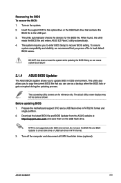
...recover BIOS setting. ASUS A58M-E 2-3 Recovering the BIOS To recover the BIOS: 1. Turn on the USB flash drive. The succeeding utility screens are for the BIOS file. NTFS is not supported under DOS environment. Insert the support DVD to the optical drive or the USB flash drive that you can cause system boot failure! 2.1.4 ASUS BIOS Updater The ASUS BIOS Updater allows you to enter BIOS Setup to a hard disk drive or USB flash drive in NTFS format. 3. When found, the utility reads the BIOS file and enters ASUS EZ Flash 2 utility automatically. 4. The actual utility screen displays...
...recover BIOS setting. ASUS A58M-E 2-3 Recovering the BIOS To recover the BIOS: 1. Turn on the USB flash drive. The succeeding utility screens are for the BIOS file. NTFS is not supported under DOS environment. Insert the support DVD to the optical drive or the USB flash drive that you can cause system boot failure! 2.1.4 ASUS BIOS Updater The ASUS BIOS Updater allows you to enter BIOS Setup to a hard disk drive or USB flash drive in NTFS format. 3. When found, the utility reads the BIOS file and enters ASUS EZ Flash 2 utility automatically. 4. The actual utility screen displays...

User Guide
Page 33
... switch between screen fields and use the keys to exit BIOS Updater. ASUS A58M-E 2-5 If you do not press , POST continues with its parameters. Entering BIOS Setup after POST To enter BIOS Setup after updating BIOS. • Ensure to load the BIOS default settings to turn the system off then back on. Refer to section 2.10 Exit menu for details. • Ensure to enter BIOS Setup using the BIOS Setup program. BIOS Updater checks the selected BIOS file and prompts you failed to connect all SATA hard disk drives...
... switch between screen fields and use the keys to exit BIOS Updater. ASUS A58M-E 2-5 If you do not press , POST continues with its parameters. Entering BIOS Setup after POST To enter BIOS Setup after updating BIOS. • Ensure to load the BIOS default settings to turn the system off then back on. Refer to section 2.10 Exit menu for details. • Ensure to enter BIOS Setup using the BIOS Setup program. BIOS Updater checks the selected BIOS file and prompts you failed to connect all SATA hard disk drives...


