
X223W LCD Monitor User's Guide
Page 16
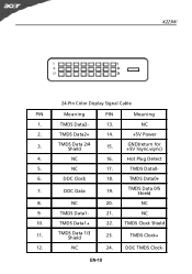
TMDS Data2+ 14. +5V Power 3. DDC Clock 18. NC 10. NC 24. NC 2. NC 16. NC 17. TMDS Data0+ 7. TMDS Clock Shield 11. TMDS Clock+ 12. TMDS Data0- 6. NC 20. TMDS Data1+ 22. Hot Plug Detect 5. NC 9. TMDS Data 1/3 Shield 23. DDC TMDS Clock- TMDS Data2- 13. TMDS Data 0/5 Shield 8. TMDS Data1- 21. X223W 24-Pin Color Display Signal Cable PIN Meaning PIN Meaning 1. TMDS Data 2/4 Shield 15. GND(return for +5V hsync.vsync) 4. EN-10 DDC Data 19.
TMDS Data2+ 14. +5V Power 3. DDC Clock 18. NC 10. NC 24. NC 2. NC 16. NC 17. TMDS Data0+ 7. TMDS Clock Shield 11. TMDS Clock+ 12. TMDS Data0- 6. NC 20. TMDS Data1+ 22. Hot Plug Detect 5. NC 9. TMDS Data 1/3 Shield 23. DDC TMDS Clock- TMDS Data2- 13. TMDS Data 0/5 Shield 8. TMDS Data1- 21. X223W 24-Pin Color Display Signal Cable PIN Meaning PIN Meaning 1. TMDS Data 2/4 Shield 15. GND(return for +5V hsync.vsync) 4. EN-10 DDC Data 19.
X223W LCD Service Guide
Page 4
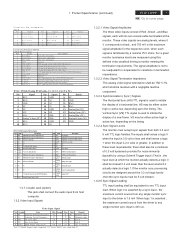
..., C3, C4, C5 is asserted , the maximum current source from PC. 1.3.2.1 Video Signal Amplitudes The three video inputs consist of a horizontal line. Product Specification (continued) ACER X223W 3 Go to cover page C o n n e c to r P in A ssig n m e n t D SU B P in 1 S ig n a l R e d -V id e o P in 6 2 G re e n -V id e o 7 3 B lu e -V id e o 8 4 NC 9... channel#2 differentialpair 2 RX2+ TMDS link #0 channel#2 differentialpair 3 GND GNDfor no link share 20 NC NC 21 NC NC 22 GND Clock shield 23 RXC+ TMDS clock differentialpair 24 RXCC1 Analog Red C2 Analog Green TMDS clock...
..., C3, C4, C5 is asserted , the maximum current source from PC. 1.3.2.1 Video Signal Amplitudes The three video inputs consist of a horizontal line. Product Specification (continued) ACER X223W 3 Go to cover page C o n n e c to r P in A ssig n m e n t D SU B P in 1 S ig n a l R e d -V id e o P in 6 2 G re e n -V id e o 7 3 B lu e -V id e o 8 4 NC 9... channel#2 differentialpair 2 RX2+ TMDS link #0 channel#2 differentialpair 3 GND GNDfor no link share 20 NC NC 21 NC NC 22 GND Clock shield 23 RXC+ TMDS clock differentialpair 24 RXCC1 Analog Red C2 Analog Green TMDS clock...
X223W LCD Service Guide
Page 22
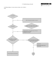
... screen when you push the "PROCEED" key. NG OK Refer "Checking the backlight unit" section" Check the video cable for output signal is blue) ACER X223W 21 Go to cover page Is backlight lit? Check the host for failure. OK NG Check if the LCD video signal cable is disconnected. Proceed "Abnormal...
... screen when you push the "PROCEED" key. NG OK Refer "Checking the backlight unit" section" Check the video cable for output signal is blue) ACER X223W 21 Go to cover page Is backlight lit? Check the host for failure. OK NG Check if the LCD video signal cable is disconnected. Proceed "Abnormal...
X223W LCD Service Guide
Page 37
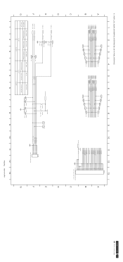
... LVA0P LVA1M LVA1P LVA2M LVA2P LVACKM LVACKP LVA3M LVA3P VLCD VLCD 12 13 P304 32 31 30 29 28 27 26 25 24 23 22 21 20 19 18 17 16 15 14 13 12 11 10 9 8 7 6 5 4 3 2 1 CVILUX-CF25302D0R0 FOR THE DOWN SIDE A B C D E F G LED_A LED_G ADC2_IN ADC1_IN LED_A LED_G TP127 R363... 0.498V 0.498V C386 0.1UF C388 0.1UF C389 0.1UF C390 0.1UF 1 2 3 4 5 6 7 8 9 LED_Blue LED_Amber KEY_ADC2 KEY_ADC1 P306 1 2 3 4 5 6 JWT-A2001WV2-06 10 11 12 13 PCB No. 6832190100P01 D E F G ACER X223W 36 Go to cover page
... LVA0P LVA1M LVA1P LVA2M LVA2P LVACKM LVACKP LVA3M LVA3P VLCD VLCD 12 13 P304 32 31 30 29 28 27 26 25 24 23 22 21 20 19 18 17 16 15 14 13 12 11 10 9 8 7 6 5 4 3 2 1 CVILUX-CF25302D0R0 FOR THE DOWN SIDE A B C D E F G LED_A LED_G ADC2_IN ADC1_IN LED_A LED_G TP127 R363... 0.498V 0.498V C386 0.1UF C388 0.1UF C389 0.1UF C390 0.1UF 1 2 3 4 5 6 7 8 9 LED_Blue LED_Amber KEY_ADC2 KEY_ADC1 P306 1 2 3 4 5 6 JWT-A2001WV2-06 10 11 12 13 PCB No. 6832190100P01 D E F G ACER X223W 36 Go to cover page