
Veriton 3200 Service Guide
Page 4
... for repair and service of customer machines. You MUST use the list provided by your regional Acer office to order FRU parts for whatever reason, a part number change is made, it supports...you with further technical details. 2. add-on your Acer office may have decided to those given in the FRU list of a machine (e.g. For ACER-AUTHORIZED SERVICE PROVIDERS, your regional web or channel. ... personnel/channel to provide you should check the most up-to the BASIC CONFIGURATION decided for Acer's "global" product offering. Please note WHEN ORDERING FRU PARTS, that you with all technical...
... for repair and service of customer machines. You MUST use the list provided by your regional Acer office to order FRU parts for whatever reason, a part number change is made, it supports...you with further technical details. 2. add-on your Acer office may have decided to those given in the FRU list of a machine (e.g. For ACER-AUTHORIZED SERVICE PROVIDERS, your regional web or channel. ... personnel/channel to provide you should check the most up-to the BASIC CONFIGURATION decided for Acer's "global" product offering. Please note WHEN ORDERING FRU PARTS, that you with all technical...
Veriton 3200 Service Guide
Page 5
... Options 34 Date and Time 36 System Security 37 Setting a Password 38 Changing or Removing the Password 39 Bypassing the Password 39 Advanced Options 40 Memory/Cache Options 40 PnP/PCI Options 42 Chipset Settings 43 Load Default Settings 45 Abort Settings Change 46 Exiting Setup 47 Chapter 3 Machine Disassembly and...
... Options 34 Date and Time 36 System Security 37 Setting a Password 38 Changing or Removing the Password 39 Bypassing the Password 39 Advanced Options 40 Memory/Cache Options 40 PnP/PCI Options 42 Chipset Settings 43 Load Default Settings 45 Abort Settings Change 46 Exiting Setup 47 Chapter 3 Machine Disassembly and...
Veriton 3200 Service Guide
Page 9
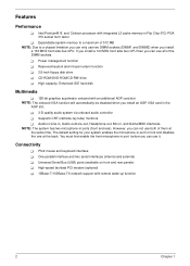
... alarm function ! 3.5-inch floppy disk drive ! High-capacity, Enhanced-IDE hard disk Multimedia ! 128-bit graphics accelerator onboard with integrated L2 cache memory in front and disables the one at the same time. The default setting for your system enables the microphone-in port in Flip Chip (FC..., and Game/MIDI interfaces NOTE: The system has two microphone-in the AGP slot. ! 3-D quality audio system via onboard audio controller ! Expandable system memory to a maximum of 512 MB NOTE: Due to a chipset limitation you can not use two DIMM sockets (DIMM1 and DIMM2) when you install an ...
... alarm function ! 3.5-inch floppy disk drive ! High-capacity, Enhanced-IDE hard disk Multimedia ! 128-bit graphics accelerator onboard with integrated L2 cache memory in front and disables the one at the same time. The default setting for your system enables the microphone-in port in Flip Chip (FC..., and Game/MIDI interfaces NOTE: The system has two microphone-in the AGP slot. ! 3-D quality audio system via onboard audio controller ! Expandable system memory to a maximum of 512 MB NOTE: Due to a chipset limitation you can not use two DIMM sockets (DIMM1 and DIMM2) when you install an ...
Veriton 3200 Service Guide
Page 16
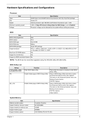
...BIOS Setup Utility. The items on the Advanced Options menu are : Memory/Cache Options PnP/PCI Options Chips Options System Memory Item Memory socket number Support memory size per socket Support maximum memory size Support memory type Support memory speed Specification 3 sockets (3 banks) 64/128/256MB 512MB SDRAM 100...booting to Enabled.) Processor voltage can be detected by the system without setting any jumper. BIOS Item Specification BIOS code programmer Acer BIOS version V4.0 BIOS ROM type Flash ROM BIOS ROM size 4Mbits BIOS ROM package 32-pin DIP package Support protocol...
...BIOS Setup Utility. The items on the Advanced Options menu are : Memory/Cache Options PnP/PCI Options Chips Options System Memory Item Memory socket number Support memory size per socket Support maximum memory size Support memory type Support memory speed Specification 3 sockets (3 banks) 64/128/256MB 512MB SDRAM 100...booting to Enabled.) Processor voltage can be detected by the system without setting any jumper. BIOS Item Specification BIOS code programmer Acer BIOS version V4.0 BIOS ROM type Flash ROM BIOS ROM size 4Mbits BIOS ROM package 32-pin DIP package Support protocol...
Veriton 3200 Service Guide
Page 17
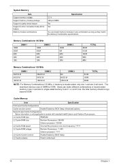
...-Level Cache Configurations Cache function control Enable/Disable by BIOS Setup L2 Cache scheme Fixed in any combination as long as they match the Memory Combination specifications. Memory Combinations-100 MHz 128M 256M 64M 32M 16M DIMM 1 128M 256M 64M 32M 16M DIMM 2 128M 0M 64M 32M 16M DIMM 3 384M 512M 192M... 96M 48M TOTAL Memory Combinations-133 MHz DIMM 1 256/DS M 64/SS M 128/SS M DIMM 2 256/DS M 64/SS M 128/SS M DIMM 3 0M 64/SS M 128/SS M 512M 192M...
...-Level Cache Configurations Cache function control Enable/Disable by BIOS Setup L2 Cache scheme Fixed in any combination as long as they match the Memory Combination specifications. Memory Combinations-100 MHz 128M 256M 64M 32M 16M DIMM 1 128M 256M 64M 32M 16M DIMM 2 128M 0M 64M 32M 16M DIMM 3 384M 512M 192M... 96M 48M TOTAL Memory Combinations-133 MHz DIMM 1 256/DS M 64/SS M 128/SS M DIMM 2 256/DS M 64/SS M 128/SS M DIMM 3 0M 64/SS M 128/SS M 512M 192M...
Veriton 3200 Service Guide
Page 25
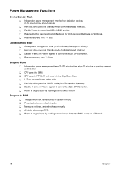
... management timer (2-120 minutes, time step=10 minutes) or pushing external switch button ! Suspend Mode ! CPU asserts STPCLK# and goes into the Stop Grant State. ! Memory is maintained in system...
... management timer (2-120 minutes, time step=10 minutes) or pushing external switch button ! Suspend Mode ! CPU asserts STPCLK# and goes into the Stop Grant State. ! Memory is maintained in system...
Veriton 3200 Service Guide
Page 27
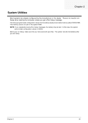
...2 20 NOTE: If you exit Setup. The system reboots immediately after you repeatedly receive Run Setup messages, the battery may be bad. This memory area is no need to run Setup, make sure that you get a Run Setup message. Before you run Setup when starting the computer unless... you have saved all open files. The Setup program loads configuration values into the battery-backed nonvolatile memory called CMOS RAM. There is not part of the system RAM. Chapter 2 System Utilities Most systems are already configured by the manufacturer ...
...2 20 NOTE: If you exit Setup. The system reboots immediately after you repeatedly receive Run Setup messages, the battery may be bad. This memory area is no need to run Setup, make sure that you get a Run Setup message. Before you run Setup when starting the computer unless... you have saved all open files. The Setup program loads configuration values into the battery-backed nonvolatile memory called CMOS RAM. There is not part of the system RAM. Chapter 2 System Utilities Most systems are already configured by the manufacturer ...

Veriton 3200 Service Guide
Page 30
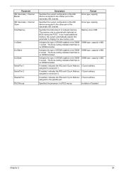
... configuration of the IDE device connected to the master port of the primary IDE channel. Level 1 Cache Specifies the first-level or the internal memory (i.e., the memory integrated into the processor) size, and whether it is enabled or disabled. Cache size in KB Floppy Drive A Shows the diskette drive A ...IDE Primary Channel Master Specifies the current configuration of the IDE Drive type, capacity device connected to the slave port of your system. None Total Memory 64 MB 1st Bank SDRAM, 32 MB 2nd Bank SDRAM, 32 MB 3rd Bank None Serial Port 1 3F8h, IRQ 4 Serial Port 2 Disabled...
... configuration of the IDE device connected to the master port of the primary IDE channel. Level 1 Cache Specifies the first-level or the internal memory (i.e., the memory integrated into the processor) size, and whether it is enabled or disabled. Cache size in KB Floppy Drive A Shows the diskette drive A ...IDE Primary Channel Master Specifies the current configuration of the IDE Drive type, capacity device connected to the slave port of your system. None Total Memory 64 MB 1st Bank SDRAM, 32 MB 2nd Bank SDRAM, 32 MB 3rd Bank None Serial Port 1 3F8h, IRQ 4 Serial Port 2 Disabled...
Veriton 3200 Service Guide
Page 31
... is automatically detected by BIOS during the POST. Specifies the presence of DRAM installed in the DIMM DIMM type, capacity in MB 2 socket. Memory size in MB 1 socket. If enabled, indicates the IRQ and I/O port Address I /O port address assigned to the slave port of the... secondary IDE channel. Parameter IDE Secondary Channel Master IDE Secondary Channel Slave Total Memory 1st Bank 2nd Bank 3rd Bank Serial Port 1 Serial Port 2 Parallel Port PS/2 Mouse Description Format Specifies the current configuration of the ...
... is automatically detected by BIOS during the POST. Specifies the presence of DRAM installed in the DIMM DIMM type, capacity in MB 2 socket. Memory size in MB 1 socket. If enabled, indicates the IRQ and I/O port Address I /O port address assigned to the slave port of the... secondary IDE channel. Parameter IDE Secondary Channel Master IDE Secondary Channel Slave Total Memory 1st Bank 2nd Bank 3rd Bank Serial Port 1 Serial Port 2 Parallel Port PS/2 Mouse Description Format Specifies the current configuration of the ...
Veriton 3200 Service Guide
Page 41
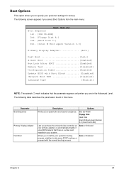
... Disk A:] 3rd. [Hard Disk C:] 4th. [Intel ® Boot Agent Version 3.0] Primary Display Adapter Auto] Fast Boot Auto] Silent Boot Enabled] Num Lock After BOOT Enabled] Memory Test Disabled] *Configuration Table Enabled] Update BIOS with the normal booting process. Parameter Boot Sequence Primary Display Adapter Fast Boot Description Options Allows you select...
... Disk A:] 3rd. [Hard Disk C:] 4th. [Intel ® Boot Agent Version 3.0] Primary Display Adapter Auto] Fast Boot Auto] Silent Boot Enabled] Num Lock After BOOT Enabled] Memory Test Disabled] *Configuration Table Enabled] Update BIOS with the normal booting process. Parameter Boot Sequence Primary Display Adapter Fast Boot Description Options Allows you select...
Veriton 3200 Service Guide
Page 42
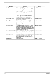
... configuration table after you hear a beep that BIOS detected during POST and while booting. English or Japanese 35 Chapter 2 Enabled or Disabled Memory Test Lets you specify whether you to Disabled speeds up . Enabled or Disabled Update BIOS w/ Boot Block When enabled, it automatically flashed... POST but before booting. The configuration table gives a summary of the computer. You may also switch to perform or bypass the memory test. This parameter is only available when Fast Boot is in graphical mode and Enabled or Disabled displays only an identification logo during...
... configuration table after you hear a beep that BIOS detected during POST and while booting. English or Japanese 35 Chapter 2 Enabled or Disabled Memory Test Lets you specify whether you to Disabled speeds up . Enabled or Disabled Update BIOS w/ Boot Block When enabled, it automatically flashed... POST but before booting. The configuration table gives a summary of the computer. You may also switch to perform or bypass the memory test. This parameter is only available when Fast Boot is in graphical mode and Enabled or Disabled displays only an identification logo during...
Veriton 3200 Service Guide
Page 47
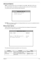
... PCI device settings. PnP/PCI Options CAUTION: Do not change any settings in the main menu. Memory/Cache Options Level 1 Cache Enabled] Level 2 Cache Enabled] Memory at 15MB-16MB Reserved for .... [System] CPU frequency Multiplier 3X] The following screen shows the Advanced Options parameters: Advanced Options !... Level 1 Cache (processor Cache) Level 2 Cache Description Lets you to avoid damaging the system. Lets you configure the system memory. Options Enabled or Disabled Enabled or Disabled Chapter 2 40 The following table describes the parameters found in this sub-menu...
... PCI device settings. PnP/PCI Options CAUTION: Do not change any settings in the main menu. Memory/Cache Options Level 1 Cache Enabled] Level 2 Cache Enabled] Memory at 15MB-16MB Reserved for .... [System] CPU frequency Multiplier 3X] The following screen shows the Advanced Options parameters: Advanced Options !... Level 1 Cache (processor Cache) Level 2 Cache Description Lets you to avoid damaging the system. Lets you configure the system memory. Options Enabled or Disabled Enabled or Disabled Chapter 2 40 The following table describes the parameters found in this sub-menu...
Veriton 3200 Service Guide
Page 48
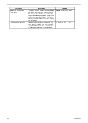
... 15MB-16MB Reserved for CPU Frequency Multiplier Description Options To prevent memory address conflicts between the system and expansion boards, reserve this memory range for this parameter. System or Expansion board Sets the Core/bus ratio of either the system or an expansion board. Some VGA cards have ...
... 15MB-16MB Reserved for CPU Frequency Multiplier Description Options To prevent memory address conflicts between the system and expansion boards, reserve this memory range for this parameter. System or Expansion board Sets the Core/bus ratio of either the system or an expansion board. Some VGA cards have ...
Veriton 3200 Service Guide
Page 50
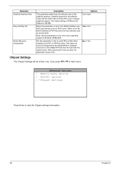
... Yes or No No or Yes Chipset Settings The Chipset Settings will be shown only if you press Alt + F4 in main menu: Advanced Options ! Memory/Cache Options ! Parameter Graphics Aperture Size Plug and Play OS Reset Resource Assignments Description This parameter determines the effective size of the graphics aperture. Note...
... Yes or No No or Yes Chipset Settings The Chipset Settings will be shown only if you press Alt + F4 in main menu: Advanced Options ! Memory/Cache Options ! Parameter Graphics Aperture Size Plug and Play OS Reset Resource Assignments Description This parameter determines the effective size of the graphics aperture. Note...
Veriton 3200 Service Guide
Page 52
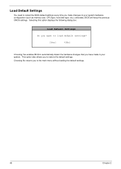
... you to the main menu without loading the default settings. 45 Chapter 2 Choosing No returns you have made in your system hardware configuration (such as memory size, CPU type, hard disk type, etc.); This option also allows you make changes to your system. otherwise, BIOS will keep the previous CMOS settings...
... you to the main menu without loading the default settings. 45 Chapter 2 Choosing No returns you have made in your system hardware configuration (such as memory size, CPU type, hard disk type, etc.); This option also allows you make changes to your system. otherwise, BIOS will keep the previous CMOS settings...
Veriton 3200 Service Guide
Page 64
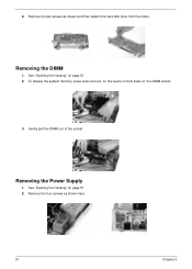
To release the system memory, press down and out on the levers on both sides of the socket. See "Opening the Housing" on page 51 2. See "Opening the Housing" on page 51 2. Removing the Power Supply 1. Remove the four screws as shown and then detach the hard disk drive from the frame. 6. Gently pull the DIMM out of the DIMM socket. 3. Removing the DIMM 1. Remove the two screws as shown here. 57 Chapter 3
To release the system memory, press down and out on the levers on both sides of the socket. See "Opening the Housing" on page 51 2. See "Opening the Housing" on page 51 2. Removing the Power Supply 1. Remove the four screws as shown and then detach the hard disk drive from the frame. 6. Gently pull the DIMM out of the DIMM socket. 3. Removing the DIMM 1. Remove the two screws as shown here. 57 Chapter 3
Veriton 3200 Service Guide
Page 68
... of the power-on password option. Onboard parallel interface controller ! I/O ports ! USB port 61 Chapter 4 If POST discovers errors in numeric co-processor and cache memory subsystem ! Three programmable timers ! Onboard serial interface controller ! Embedded hard disk interface and one diskette drive interface ! PS/2-compatible keyboard port ! PS/2-compatible mouse port... on the system, the Power-on screen, generates a check point code at port 80h or even halts the system if the error is fatal. Direct Memory Access (DMA) controller !
... of the power-on password option. Onboard parallel interface controller ! I/O ports ! USB port 61 Chapter 4 If POST discovers errors in numeric co-processor and cache memory subsystem ! Three programmable timers ! Onboard serial interface controller ! Embedded hard disk interface and one diskette drive interface ! PS/2-compatible keyboard port ! PS/2-compatible mouse port... on the system, the Power-on screen, generates a check point code at port 80h or even halts the system if the error is fatal. Direct Memory Access (DMA) controller !
Veriton 3200 Service Guide
Page 69
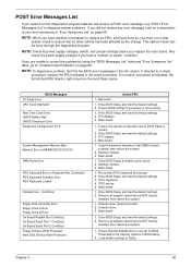
...Port 1 Conflict(s) On Board Serial Port 2 Conflict(s) Floppy Drive(s) Write Protected Hard Disk Drive(s) Write Protected Action/FRU 1. Main board. 1. Memory module. 3. Main board 1. Enter BIOS Setup and load the default settings. 2. installed, then reboot the system. 1. Diskette drive cable/connection.... I/O Parity Error CPU Clock Mismatch Real Time Clock Error CMOS Battery Bad CMOS Checksum Error Equipment Configuration Error System Management Memory Bad Memory Error at MMMM:SSSS:OOOOh RAM Parity Error PS/2 Keyboard Error or Keyboard Not Connected PS/2 Keyboard Interface Error PS/2...
...Port 1 Conflict(s) On Board Serial Port 2 Conflict(s) Floppy Drive(s) Write Protected Hard Disk Drive(s) Write Protected Action/FRU 1. Main board. 1. Memory module. 3. Main board 1. Enter BIOS Setup and load the default settings. 2. installed, then reboot the system. 1. Diskette drive cable/connection.... I/O Parity Error CPU Clock Mismatch Real Time Clock Error CMOS Battery Bad CMOS Checksum Error Equipment Configuration Error System Management Memory Bad Memory Error at MMMM:SSSS:OOOOh RAM Parity Error PS/2 Keyboard Error or Keyboard Not Connected PS/2 Keyboard Interface Error PS/2...

Veriton 3200 Service Guide
Page 70
... and mouse. 2. BIOS Messages IDE Drive 0 Error IDE Drive 1 Error IDE Drive 2 Error IDE Drive 3 Error IRQ Setting Error Expansion ROM Allocation Fail I/O Resource Conflict(s) Memory Resource Conflict(s) PCI Device Error PS/2 Pointing Device Interface Error PS/2 Pointing Device Error DMI Table Was Destroyed Press Ctrl + Alt + Esc key to enter...
... and mouse. 2. BIOS Messages IDE Drive 0 Error IDE Drive 1 Error IDE Drive 2 Error IDE Drive 3 Error IRQ Setting Error Expansion ROM Allocation Fail I/O Resource Conflict(s) Memory Resource Conflict(s) PCI Device Error PS/2 Pointing Device Interface Error PS/2 Pointing Device Error DMI Table Was Destroyed Press Ctrl + Alt + Esc key to enter...
Veriton 3200 Service Guide
Page 71
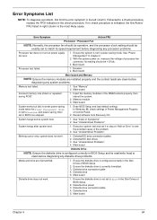
...is configured correctly in the Disk Drives of BIOS Setup. 2. Its reading should be +12Vdc. 3. Main board and Memory NOTE: Ensure the memory modules are installed properly and the contact leads are mismatched. 1. Main board. Ensure the diskette drive is the most ... Diskette drive 5. With the system power on Error" to see the potential cause of Control Panel. 2. Processor test failed. 1. See "Memory" 2. Diskette/IDE drive connection/cables 2. Diskette drive 5. Diskette drive connection/cable 4. If no check procedure is clean before diagnosing any diskette...
...is configured correctly in the Disk Drives of BIOS Setup. 2. Its reading should be +12Vdc. 3. Main board and Memory NOTE: Ensure the memory modules are installed properly and the contact leads are mismatched. 1. Main board. Ensure the diskette drive is the most ... Diskette drive 5. With the system power on Error" to see the potential cause of Control Panel. 2. Processor test failed. 1. See "Memory" 2. Diskette/IDE drive connection/cables 2. Diskette drive 5. Diskette drive connection/cable 4. If no check procedure is clean before diagnosing any diskette...


