
Veriton 3200 Service Guide
Page 5
... 2 Connectivity 2 Front Panel 3 Rear panel 4 Main Board Layout 5 Keyboard 6 Programmable keys 6 Internet/Suspend keys 6 Multimedia keys 7 Volume control/Mute 7 Cursor keys 7 Lock keys 7 Windows keys 8 Hardware Specifications and Configurations 9 Power Management Functions 18 Chapter 2 System Utilities 20 Entering Setup 21 System Information 23 Product Information 25 Disk Drives 26 Onboard Peripherals 30 Power Management 32 Boot Options 34 Date and Time 36 System Security 37 Setting a Password 38 Changing or Removing the Password 39 Bypassing the Password 39...
... 2 Connectivity 2 Front Panel 3 Rear panel 4 Main Board Layout 5 Keyboard 6 Programmable keys 6 Internet/Suspend keys 6 Multimedia keys 7 Volume control/Mute 7 Cursor keys 7 Lock keys 7 Windows keys 8 Hardware Specifications and Configurations 9 Power Management Functions 18 Chapter 2 System Utilities 20 Entering Setup 21 System Information 23 Product Information 25 Disk Drives 26 Onboard Peripherals 30 Power Management 32 Boot Options 34 Date and Time 36 System Security 37 Setting a Password 38 Changing or Removing the Password 39 Bypassing the Password 39...
Veriton 3200 Service Guide
Page 9
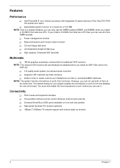
... install an AGP VGA card in front and disables the one at the same time. The default setting for your system enables the microphone-in port in the AGP slot. ! 3-D quality audio system via onboard audio controller ! High-speed fax/data PCI modem (optional) ! 10Base-T/100Base-TX network support with an additional AGP card slot NOTE: The onboard VGA function will automatically be disabled when you install a 133 MHZ front side bus CPU. Supports...
... install an AGP VGA card in front and disables the one at the same time. The default setting for your system enables the microphone-in port in the AGP slot. ! 3-D quality audio system via onboard audio controller ! High-speed fax/data PCI modem (optional) ! 10Base-T/100Base-TX network support with an additional AGP card slot NOTE: The onboard VGA function will automatically be disabled when you install a 133 MHZ front side bus CPU. Supports...
Veriton 3200 Service Guide
Page 11
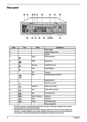
... ports (front and rear). You must first enable the front microphone-in front and disables the one at the same time. Connect the monitor to the VGA port instead. † The system has two microphone-in jack m Lime Audio-out/Line-out jack n Blue CRT monitor port o Teal or Turquoise Serial port p Black USB ports q Purple PS/2 keyboard port r Power cord socket * The CRT monitor port is automatically disabled when an add-on VGA card...
... ports (front and rear). You must first enable the front microphone-in front and disables the one at the same time. Connect the monitor to the VGA port instead. † The system has two microphone-in jack m Lime Audio-out/Line-out jack n Blue CRT monitor port o Teal or Turquoise Serial port p Black USB ports q Purple PS/2 keyboard port r Power cord socket * The CRT monitor port is automatically disabled when an add-on VGA card...
Veriton 3200 Service Guide
Page 19
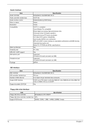
... wavetable synthesizers and MIDI devices Integrated dual game port Meets PC 97/PC98 and WHQL specifications Yes 44.1 KHz Yes Supported On audio-I/O board (connects via CN8) Supported On audio-I/O board (connects via CN8) QFP64 IDE Interface Item IDE controller IDE controller resident bus Number of IDE channel Support IDE interface Support bootable CD-ROM Specification Embedded in Intel 82801BA ICH II PCI bus 2 on-board: 40-pin hard disk drive connector, E-IDE (up to PIO...
... wavetable synthesizers and MIDI devices Integrated dual game port Meets PC 97/PC98 and WHQL specifications Yes 44.1 KHz Yes Supported On audio-I/O board (connects via CN8) Supported On audio-I/O board (connects via CN8) QFP64 IDE Interface Item IDE controller IDE controller resident bus Number of IDE channel Support IDE interface Support bootable CD-ROM Specification Embedded in Intel 82801BA ICH II PCI bus 2 on-board: 40-pin hard disk drive connector, E-IDE (up to PIO...
Veriton 3200 Service Guide
Page 31
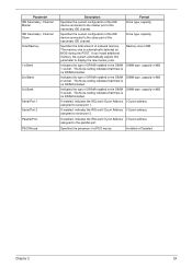
... there is no DRAM installed. If enabled, indicates the IRQ and I/O port Address I/O port address assigned to display the new memory size. Parameter IDE Secondary Channel Master IDE Secondary Channel Slave Total Memory 1st Bank 2nd Bank 3rd Bank Serial Port 1 Serial Port 2 Parallel Port PS/2 Mouse Description Format Specifies the current configuration of the IDE device connected to the master port of onboard memory. Drive type, capacity Specifies the total...
... there is no DRAM installed. If enabled, indicates the IRQ and I/O port Address I/O port address assigned to display the new memory size. Parameter IDE Secondary Channel Master IDE Secondary Channel Slave Total Memory 1st Bank 2nd Bank 3rd Bank Serial Port 1 Serial Port 2 Parallel Port PS/2 Mouse Description Format Specifies the current configuration of the IDE device connected to the master port of onboard memory. Drive type, capacity Specifies the total...
Veriton 3200 Service Guide
Page 36
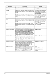
... Multi-DMA modes enhance hard disk performance by allowing the use . Cylinder Specifies your hard disk's number of your Type parameter setting. setting Hard Disk LBA Mode Set to Auto, the BIOS utility automatically detects if the installed hard disk supports the function, it is Hard Disk. However, besides enabling these features in better hard disk performance. Only Device Detection Mode is set to User, the item Head will be available; configurable. The default is non-configurable. Parameter Description Options Device Type Display the type of 256...
... Multi-DMA modes enhance hard disk performance by allowing the use . Cylinder Specifies your hard disk's number of your Type parameter setting. setting Hard Disk LBA Mode Set to Auto, the BIOS utility automatically detects if the installed hard disk supports the function, it is Hard Disk. However, besides enabling these features in better hard disk performance. Only Device Detection Mode is set to User, the item Head will be available; configurable. The default is non-configurable. Parameter Description Options Device Type Display the type of 256...
Veriton 3200 Service Guide
Page 37
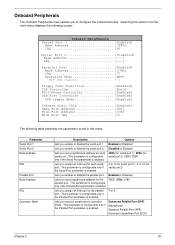
...Port 1 Serial Port 2 Base Address IRQ Parallel Port Base Address IRQ Operation Mode Description Options Lets you assign an interrupt for the parallel port. Selecting this option from the main menu displays the following screen: Onboard Peripherals Serial Port 1 Enabled] Base Address 3F8h] IRQ 4] Serial Port 2 Disabled] Base Address IRQ Parallel Port Enabled] Base Address 378h] IRQ 7] Operation Mode EPP] ECP DMA Channel Floppy Disk Controller Enabled] IDE Controller Both] PS/2 Mouse Controller Enabled] USB Host Controller Enabled] USB Legacy Mode Enabled] Onboard Audio...
...Port 1 Serial Port 2 Base Address IRQ Parallel Port Base Address IRQ Operation Mode Description Options Lets you assign an interrupt for the parallel port. Selecting this option from the main menu displays the following screen: Onboard Peripherals Serial Port 1 Enabled] Base Address 3F8h] IRQ 4] Serial Port 2 Disabled] Base Address IRQ Parallel Port Enabled] Base Address 378h] IRQ 7] Operation Mode EPP] ECP DMA Channel Floppy Disk Controller Enabled] IDE Controller Both] PS/2 Mouse Controller Enabled] USB Host Controller Enabled] USB Legacy Mode Enabled] Onboard Audio...
Veriton 3200 Service Guide
Page 39
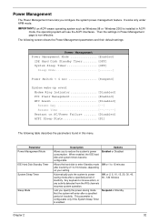
... on AC/Power Failure ....... [Disabled] ACPI Sleep State S1] The following table describes the parameters found in ACPI mode, the operating system will enter after inactivity of 1 to powersaving mode after a specified period of inactivity. Any keyboard or mouse action, or any activity detected from the IRQ channels resumes system operation. Parameter Power Management Mode IDE Hard Disk Standby Timer System Sleep Timer Sleep Mode Description Options Allows you to...
... on AC/Power Failure ....... [Disabled] ACPI Sleep State S1] The following table describes the parameters found in ACPI mode, the operating system will enter after inactivity of 1 to powersaving mode after a specified period of inactivity. Any keyboard or mouse action, or any activity detected from the IRQ channels resumes system operation. Parameter Power Management Mode IDE Hard Disk Standby Timer System Sleep Timer Sleep Mode Description Options Allows you to...
Veriton 3200 Service Guide
Page 41
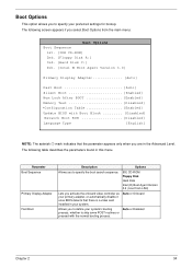
... is a video card installed in your system. Auto or Onboard Allows you to specify your preferred settings for bootup. IDE CD-ROM Floppy Disk Hard Disk Intel (R) Boot Agent Version 3.0 ( boot from the main menu: Boot Options Boot Sequence 1st. [IDE CD-ROM] 2nd. [Floppy Disk A:] 3rd. [Hard Disk C:] 4th. [Intel ® Boot Agent Version 3.0] Primary Display Adapter Auto] Fast Boot Auto] Silent Boot Enabled] Num Lock After BOOT Enabled] Memory Test Disabled] *Configuration Table Enabled] Update BIOS with the normal booting process. The...
... is a video card installed in your system. Auto or Onboard Allows you to specify your preferred settings for bootup. IDE CD-ROM Floppy Disk Hard Disk Intel (R) Boot Agent Version 3.0 ( boot from the main menu: Boot Options Boot Sequence 1st. [IDE CD-ROM] 2nd. [Floppy Disk A:] 3rd. [Hard Disk C:] 4th. [Intel ® Boot Agent Version 3.0] Primary Display Adapter Auto] Fast Boot Auto] Silent Boot Enabled] Num Lock After BOOT Enabled] Memory Test Disabled] *Configuration Table Enabled] Update BIOS with the normal booting process. The...
Veriton 3200 Service Guide
Page 49
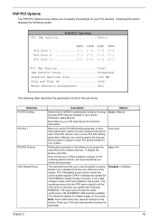
... VGA cards so that you need to let BIOS automatically configure the plugand-play (PnP) devices installed in this sub-menu. Selecting this option displays the following screen: PnP/PCI Options PCI IRQ Setting Auto] INTA PCI Slot 1 PCI Slot 2 PCI Slot 3 INTB INTC INTD PCI IRQ Sharing Yes] VGA Palette Snoop Disabled] Graphics Aperture Size 64] MB Plug and Play OS Yes] Reset Resource Assignments No] The following table describes the parameters found in your VGA card manual before setting...
... VGA cards so that you need to let BIOS automatically configure the plugand-play (PnP) devices installed in this sub-menu. Selecting this option displays the following screen: PnP/PCI Options PCI IRQ Setting Auto] INTA PCI Slot 1 PCI Slot 2 PCI Slot 3 INTB INTC INTD PCI IRQ Sharing Yes] VGA Palette Snoop Disabled] Graphics Aperture Size 64] MB Plug and Play OS Yes] Reset Resource Assignments No] The following table describes the parameters found in your VGA card manual before setting...
Veriton 3200 Service Guide
Page 58
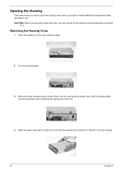
... it outward to install additional components inside the system unit. Turn the housing back. 3. Set the screws aside, you have turned off the system and all peripherals connected to it. Opening the Housing This section tells you how to open the housing cover when you need them when replacing the right panel of the unit. 4. Remove the two screws using a screw driver from the housing...
... it outward to install additional components inside the system unit. Turn the housing back. 3. Set the screws aside, you have turned off the system and all peripherals connected to it. Opening the Housing This section tells you how to open the housing cover when you need them when replacing the right panel of the unit. 4. Remove the two screws using a screw driver from the housing...
Veriton 3200 Service Guide
Page 67
Index of Error Codes and Error Beeps ! Index of Error Messages ! Power-On Self-Test (POST) ! Undetermined Problems Chapter 4 Chapter 4 60 Index of Error Symptoms ! Troubleshooting This chapter provides troubleshooting information for the Veriton 3200: !
Index of Error Codes and Error Beeps ! Index of Error Messages ! Power-On Self-Test (POST) ! Undetermined Problems Chapter 4 Chapter 4 60 Index of Error Symptoms ! Troubleshooting This chapter provides troubleshooting information for the Veriton 3200: !
Veriton 3200 Service Guide
Page 69
... BIOS setting for a description of your error symptoms in the check procedure. Remove all adapter cards that are unable to correct the problem by the change. Diskette drive cable/connection. 2. NOTE: Check all power supply voltages, switch, and jumper settings before you are NOT factory- Insert the memory modules in Setup. Chapter 4 62 Also check the power supply voltages if you must run the diagnostics program tests but did receive a POST error message, use "POST Error Messages List...
... BIOS setting for a description of your error symptoms in the check procedure. Remove all adapter cards that are unable to correct the problem by the change. Diskette drive cable/connection. 2. NOTE: Check all power supply voltages, switch, and jumper settings before you are NOT factory- Insert the memory modules in Setup. Chapter 4 62 Also check the power supply voltages if you must run the diagnostics program tests but did receive a POST error message, use "POST Error Messages List...

Veriton 3200 Service Guide
Page 70
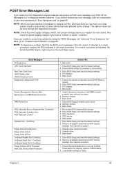
... default settings in Setup. 2. Remove all adapter cards that are NOT factoryinstalled, then reboot the system 1. Load default settings in Setup. 2. Enter BIOS Setup and set the Reset Resource Assignments of the PnP/PCI Options to Yes, then reboot the system. 3. Press Esc to reject NMI error or press any key to reboot Insert system diskette and press key to enter Setup and reconfigure the system. 1. Enter BIOS Setup and load the default settings. 3. IDE hard disk drive cable/connection. 5. IDE hard disk drive power. 4. Check IDE drive jumper. 3. PS/2 keyboard...
... default settings in Setup. 2. Remove all adapter cards that are NOT factoryinstalled, then reboot the system 1. Load default settings in Setup. 2. Enter BIOS Setup and set the Reset Resource Assignments of the PnP/PCI Options to Yes, then reboot the system. 3. Press Esc to reject NMI error or press any key to reboot Insert system diskette and press key to enter Setup and reconfigure the system. 1. Enter BIOS Setup and load the default settings. 3. IDE hard disk drive cable/connection. 5. IDE hard disk drive power. 4. Check IDE drive jumper. 3. PS/2 keyboard...
Veriton 3200 Service Guide
Page 72
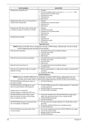
...shutting off. Diskette drive connection/cable 4. Hard disk drive has write error. 1. Turn up the sound volume. 3. CD/DVD-ROM Drive NOTE: Ensure CD/DVD-ROM drive is configured correctly in BIOS Setup, cable/jumper are set correctly before diagnosing any CD/DVD-ROM drive problems. CD/DVD-ROM drive LED doesn't come on for more than 30 seconds before diagnosing any hard disk drive problems. Hard disk drive test failed. 1. CD/DVD-ROM is pressed and held. 1. CD/DVD-ROM drive power. 3. Ensure the headphone jack of hard disk LED connector. 2. Error Symptom Action/FRU...
...shutting off. Diskette drive connection/cable 4. Hard disk drive has write error. 1. Turn up the sound volume. 3. CD/DVD-ROM Drive NOTE: Ensure CD/DVD-ROM drive is configured correctly in BIOS Setup, cable/jumper are set correctly before diagnosing any CD/DVD-ROM drive problems. CD/DVD-ROM drive LED doesn't come on for more than 30 seconds before diagnosing any hard disk drive problems. Hard disk drive test failed. 1. CD/DVD-ROM is pressed and held. 1. CD/DVD-ROM drive power. 3. Ensure the headphone jack of hard disk LED connector. 2. Error Symptom Action/FRU...

Veriton 3200 Service Guide
Page 73
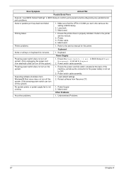
... default settings (if screen is set correctly. 2. Main board 1. Modem 1. Monitor signal connection/cable. 2. Monitor 3. Video adapter card 4. RTC battery. 3. Error Symptom Real-time clock is installed properly. 1. Main board Audio 1. Ensure the modem card is inaccurate. Remove all non-factory-installed cards. 2. If PCI modem card is used , ensure the modem ring-in cable from suspend mode. Main board Chapter 4 66 Video adapter failed. Modem ring cannot wake up system from modem adapter card to receive messages and/or fax. 1. Display problem not listed...
... default settings (if screen is set correctly. 2. Main board 1. Modem 1. Monitor signal connection/cable. 2. Monitor 3. Video adapter card 4. RTC battery. 3. Error Symptom Real-time clock is installed properly. 1. Main board Audio 1. Ensure the modem card is inaccurate. Remove all non-factory-installed cards. 2. If PCI modem card is used , ensure the modem ring-in cable from suspend mode. Main board Chapter 4 66 Video adapter failed. Modem ring cannot wake up system from modem adapter card to receive messages and/or fax. 1. Display problem not listed...
Veriton 3200 Service Guide
Page 74
... switch (situated at the back of Power Management is not set to the service manual for the power cable) is the same as the setting in BIOS Setup of the machine, just above the connector for the printer. Refer to OFF. 2. in BIOS Setup. 2. No system power, or power supply fan is properly installed. Undetermined Problems 67 Chapter 4 Loop-back. 3. Power switch cable assembly. Main board. Ensure the Power Switch < 4 sec. Keyboard Power Supply Pressing power switch does not turn off the system.) 1. Make...
... switch (situated at the back of Power Management is not set to the service manual for the power cable) is the same as the setting in BIOS Setup of the machine, just above the connector for the printer. Refer to OFF. 2. in BIOS Setup. 2. No system power, or power supply fan is properly installed. Undetermined Problems 67 Chapter 4 Loop-back. 3. Power switch cable assembly. Main board. Ensure the Power Switch < 4 sec. Keyboard Power Supply Pressing power switch does not turn off the system.) 1. Make...
Veriton 3200 Service Guide
Page 103
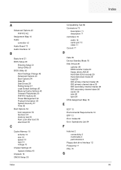
... 36 Boot Options 34 boot sequence 34 fast boot 34 memory test 35 Num Lock after boot 35 silent boot 35 C Cache Memory 10 scheme 10 size 10 speed 10 type 10 voltage 10 Chipset Settings 43 System Utilities 43 Chipsets 16 CMOS Setup 20 Index Index Compatibility Test 86 Connectors 70 Description 71 description 71 controllers 16 audio 12 serial port 13 video 11 Current 17 D Date 36 Device Standby Mode 18 Disk Drives 26...
... 36 Boot Options 34 boot sequence 34 fast boot 34 memory test 35 Num Lock after boot 35 silent boot 35 C Cache Memory 10 scheme 10 size 10 speed 10 type 10 voltage 10 Chipset Settings 43 System Utilities 43 Chipsets 16 CMOS Setup 20 Index Index Compatibility Test 86 Connectors 70 Description 71 description 71 controllers 16 audio 12 serial port 13 video 11 Current 17 D Date 36 Device Standby Mode 18 Disk Drives 26...
Veriton 3200 Service Guide
Page 105
R rear panel 4 Removal and Replacement 48 Replacement Assembly, Machine 48 RIMM Removing 57 RMA 74 Routing Map 14 S SCO UNIX/Linux Environment Test 93 Security 37 disk drive control 37 floppy drive 37 hard disk drive 37 Setup password 37 Serial Port 13 socket memory 9 Socket 370 9 Suspend Mode 18 Switching Power Supply 102W 17 Symptoms List 64 Audio 66 CD/DVD-ROM Drive 65 Diskette Drive 64 Keyboard 67 Memory 64 Modem 66 Monitor 66 Other 67 Parallel Port 67 Power Supply 67 Processor / Processor Fan 64 Real-Time...
R rear panel 4 Removal and Replacement 48 Replacement Assembly, Machine 48 RIMM Removing 57 RMA 74 Routing Map 14 S SCO UNIX/Linux Environment Test 93 Security 37 disk drive control 37 floppy drive 37 hard disk drive 37 Setup password 37 Serial Port 13 socket memory 9 Socket 370 9 Suspend Mode 18 Switching Power Supply 102W 17 Symptoms List 64 Audio 66 CD/DVD-ROM Drive 65 Diskette Drive 64 Keyboard 67 Memory 64 Modem 66 Monitor 66 Other 67 Parallel Port 67 Power Supply 67 Processor / Processor Fan 64 Real-Time...
Veriton 3200 User Guide
Page 57
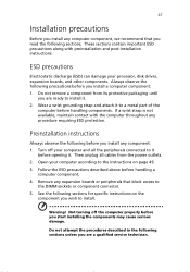
...-installation instructions. Not turning off your processor, disk drives, expansion boards, and other components. Wear a wrist grounding strap and attach it . Remove any component: 1. Then unplug all the peripherals connected to it before you install any expansion boards or peripherals that you read the following sections for specific instructions on page 49. 3. ESD precautions Electrostatic discharge (ESD) can damage your computer and all cables...
...-installation instructions. Not turning off your processor, disk drives, expansion boards, and other components. Wear a wrist grounding strap and attach it . Remove any component: 1. Then unplug all the peripherals connected to it before you install any expansion boards or peripherals that you read the following sections for specific instructions on page 49. 3. ESD precautions Electrostatic discharge (ESD) can damage your computer and all cables...


