
Veriton 3200 Service Guide
Page 4
...provide you should check the most up-to those given in the FRU list of customer machines. In such cases, please contact your regional web or channel. For ACER-AUTHORIZED SERVICE PROVIDERS, your regional office MAY have a DIFFERENT part number code to -date information available on ... FEATURES will not be covered in the printed Service Guide. To better fit local market requirements and enhance product competitiveness, your Acer office may have decided to the BASIC CONFIGURATION decided for repair and service of this printed Service Guide. Preface Before using this...
...provide you should check the most up-to those given in the FRU list of customer machines. In such cases, please contact your regional web or channel. For ACER-AUTHORIZED SERVICE PROVIDERS, your regional office MAY have a DIFFERENT part number code to -date information available on ... FEATURES will not be covered in the printed Service Guide. To better fit local market requirements and enhance product competitiveness, your Acer office may have decided to the BASIC CONFIGURATION decided for repair and service of this printed Service Guide. Preface Before using this...
Veriton 3200 Service Guide
Page 27
... by the manufacturer or the dealer. This memory area is no need to run Setup, make sure that you get a Run Setup message. In this case, the system cannot retain configuration values in CMOS. Before you run Setup when starting the computer unless you have saved all open files. There is...
... by the manufacturer or the dealer. This memory area is no need to run Setup, make sure that you get a Run Setup message. In this case, the system cannot retain configuration values in CMOS. Before you run Setup when starting the computer unless you have saved all open files. There is...
Veriton 3200 Service Guide
Page 42
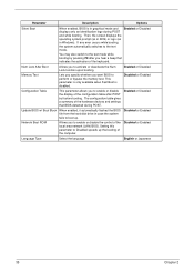
... . Setting this parameter to perform or bypass the memory test. Then, the screen displays the operating system prompt (as in DOS) or logo (as in case the system fails to the text mode while booting by pressing F9 after POST but before booting. This parameter is only available when Fast Boot...
... . Setting this parameter to perform or bypass the memory test. Then, the screen displays the operating system prompt (as in DOS) or logo (as in case the system fails to the text mode while booting by pressing F9 after POST but before booting. This parameter is only available when Fast Boot...
Veriton 3200 Service Guide
Page 57
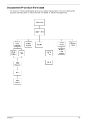
Disassembly Procedure Flowchart The flowchart on the succeeding page gives you a graphical representation on the entire disassembly sequence and instructs you on the components that need to be removed during servicing. Main Unit Upper Case FDD & DVD Bracket Power Supply DVDROM FDD DIMM CPU Fan HDD Bracket CPU HDD Main board Front Panel Audio & USB Board Modem Card Chapter 3 50
Disassembly Procedure Flowchart The flowchart on the succeeding page gives you a graphical representation on the entire disassembly sequence and instructs you on the components that need to be removed during servicing. Main Unit Upper Case FDD & DVD Bracket Power Supply DVDROM FDD DIMM CPU Fan HDD Bracket CPU HDD Main board Front Panel Audio & USB Board Modem Card Chapter 3 50
Veriton 3200 Service Guide
Page 58
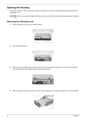
..., make sure that you will need to install additional components inside the system unit. Removing the Housing Cover 1. Turn the housing back. 3. Slide the upper case back out about an inch and then gently pull it outward to detach it . Remove the two screws using a screw driver from the housing. 51...
..., make sure that you will need to install additional components inside the system unit. Removing the Housing Cover 1. Turn the housing back. 3. Slide the upper case back out about an inch and then gently pull it outward to detach it . Remove the two screws using a screw driver from the housing. 51...
Veriton 3200 Service Guide
Page 59
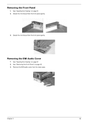
Remove the EMI audio cover from the front panel gently. 3. Removing the EMI Audio Cover 1. Detach the front bezel from the lower case. Chapter 3 52 See "Opening the Housing" on page 51 2. See "Opening the Housing" on page 51 2. Detach the front bezel from the front panel gently. See "Removing the Front Panel" on page 52 3. Removing the Front Panel 1.
Remove the EMI audio cover from the front panel gently. 3. Removing the EMI Audio Cover 1. Detach the front bezel from the lower case. Chapter 3 52 See "Opening the Housing" on page 51 2. See "Opening the Housing" on page 51 2. Detach the front bezel from the front panel gently. See "Removing the Front Panel" on page 52 3. Removing the Front Panel 1.

Veriton 3200 Service Guide
Page 61
3. Disconnect the micro switch cable from the frame. Remove the four screws as shown here then detach the DVD-ROM drive from the main board. 6. Disconnect the power and floppy disk drive cables from the lower case. 7. Pull the FDD and DVD frame from the floppy disk drive. 4. Disconnect the power cable, IDE cable, and audio cable from the DVD-ROM drive. 5. Chapter 3 54
3. Disconnect the micro switch cable from the frame. Remove the four screws as shown here then detach the DVD-ROM drive from the main board. 6. Disconnect the power and floppy disk drive cables from the lower case. 7. Pull the FDD and DVD frame from the floppy disk drive. 4. Disconnect the power cable, IDE cable, and audio cable from the DVD-ROM drive. 5. Chapter 3 54
Veriton 3200 Service Guide
Page 63
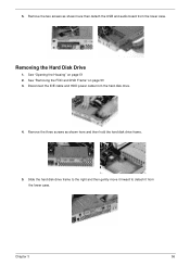
See "Opening the Housing" on page 53 3. Slide the hard disk drive frame to the right and then gently move it inward to detach it from the lower case. Remove the two screws as shown here and then hold the hard disk drive frame. 5. Chapter 3 56 Remove the three screws as shown here then detach the USB and audio board from the lower case. Disconnect the IDE cable and HDD power cable from the hard disk drive. 4. See "Removing the FDD and DVD Frame" on page 51 2. Removing the Hard Disk Drive 1. 5.
See "Opening the Housing" on page 53 3. Slide the hard disk drive frame to the right and then gently move it inward to detach it from the lower case. Remove the two screws as shown here and then hold the hard disk drive frame. 5. Chapter 3 56 Remove the three screws as shown here then detach the USB and audio board from the lower case. Disconnect the IDE cable and HDD power cable from the hard disk drive. 4. See "Removing the FDD and DVD Frame" on page 51 2. Removing the Hard Disk Drive 1. 5.
Veriton 3200 Service Guide
Page 66
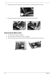
See "Opening the Housing" on page 53 3. Remove the seven screws as shown here then detach the main board from the socket carefully. Removing the Main board 1. Lift up the socket lever and then pull the CPU out from the lower case. 59 Chapter 3 3. See "Removing the FDD and DVD Frame" on page 51 2. Press down and pry the screwdriver outward to detach the metal bracket from the socket. 4.
See "Opening the Housing" on page 53 3. Remove the seven screws as shown here then detach the main board from the socket carefully. Removing the Main board 1. Lift up the socket lever and then pull the CPU out from the lower case. 59 Chapter 3 3. See "Removing the FDD and DVD Frame" on page 51 2. Press down and pry the screwdriver outward to detach the metal bracket from the socket. 4.
Veriton 3200 Service Guide
Page 86
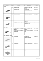
.../Bracket assembly 1-5 I/O BRACKET ASSEMBLY IO BRACKET(S58M)H34 60.97504.001 1-1 HDD BRACKET BRACKET HDD SECC H34 33.97501.001 1-6 UPPER CASE ASSEMBLY UP CASE D002 H34 60.97503.001 79 Chapter 6 VGA 8MB LT VANTA LOW PROFILE VGA 2MX32MB LOWPROFILE LEADTEX 54.02130.001 54.0205E.091 S58M AUDIO/...
.../Bracket assembly 1-5 I/O BRACKET ASSEMBLY IO BRACKET(S58M)H34 60.97504.001 1-1 HDD BRACKET BRACKET HDD SECC H34 33.97501.001 1-6 UPPER CASE ASSEMBLY UP CASE D002 H34 60.97503.001 79 Chapter 6 VGA 8MB LT VANTA LOW PROFILE VGA 2MX32MB LOWPROFILE LEADTEX 54.02130.001 54.0205E.091 S58M AUDIO/...
Veriton 3200 Service Guide
Page 87
Picture No. ASSEMBLY LOW CASE D002 60.97502.001 H34 NS FRONT BEZEL ASSY FRONT BEZEL VT3200 60.97505.001 H34 1-4 ROTATE FRAME ASSEMBLY ROTATE FRAME 60.97506.001 H34 ....040 91.62C07.041 91.62C07.042 91.62C07.043 91.62C07.046 91.62C07.049 91.62C07.04A 91.62C07.04B 80 Partname 1-7 LOWER CASE Description Part No.
Picture No. ASSEMBLY LOW CASE D002 60.97502.001 H34 NS FRONT BEZEL ASSY FRONT BEZEL VT3200 60.97505.001 H34 1-4 ROTATE FRAME ASSEMBLY ROTATE FRAME 60.97506.001 H34 ....040 91.62C07.041 91.62C07.042 91.62C07.043 91.62C07.046 91.62C07.049 91.62C07.04A 91.62C07.04B 80 Partname 1-7 LOWER CASE Description Part No.
Veriton 3200 User Guide
Page 32
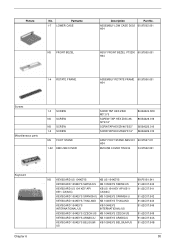
.../DVD. Make sure that the label or title side of dirt or damage can be purchased in a circular motion. • Clean your discs in a disk case when not in use a clean, dust-free cloth and wipe in a straight line from successfully reading the disc. • When handling discs, always hold it...
.../DVD. Make sure that the label or title side of dirt or damage can be purchased in a circular motion. • Clean your discs in a disk case when not in use a clean, dust-free cloth and wipe in a straight line from successfully reading the disc. • When handling discs, always hold it...
Veriton 3200 User Guide
Page 85
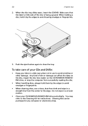
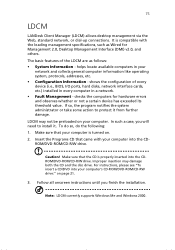
... not a certain device has exceeded its threshold value. To do so, do the following: 1. Note: LDCM currently supports Windows Me and Windows 2000. In such a case, you finish the installation. Make sure that came with the leading management specifications, such as follows: • System Information - Improper insertion may not be preloaded...
... not a certain device has exceeded its threshold value. To do so, do the following: 1. Note: LDCM currently supports Windows Me and Windows 2000. In such a case, you finish the installation. Make sure that came with the leading management specifications, such as follows: • System Information - Improper insertion may not be preloaded...
Veriton 3200 User Guide
Page 92
This chapter tells you what to do in case your dealer or the technical support center for assistance. However, if a more serious problem arises, contact your computer is not working properly.
This chapter tells you what to do in case your dealer or the technical support center for assistance. However, if a more serious problem arises, contact your computer is not working properly.

