
Veriton 3200 Service Guide
Page 16
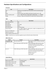
BIOS Item Specification BIOS code programmer Acer BIOS version V4.0 BIOS ROM type Flash ROM BIOS ROM size 4Mbits BIOS ROM package 32-pin DIP package Support protocol PCI 2.1, APM1.2, DMI 2.00.1, E-...® Pentium III processors with Flip Chip-PGA package Socket 370 Celeron processor upto 766 MHz and Pentium III processor upto 1 GHz 0 MHz (If Stop CPU Clock in Sleep State the BIOS Setup is booting to BIOS boot block feature No NOTE: The BIOS can be overwritten...
BIOS Item Specification BIOS code programmer Acer BIOS version V4.0 BIOS ROM type Flash ROM BIOS ROM size 4Mbits BIOS ROM package 32-pin DIP package Support protocol PCI 2.1, APM1.2, DMI 2.00.1, E-...® Pentium III processors with Flip Chip-PGA package Socket 370 Celeron processor upto 766 MHz and Pentium III processor upto 1 GHz 0 MHz (If Stop CPU Clock in Sleep State the BIOS Setup is booting to BIOS boot block feature No NOTE: The BIOS can be overwritten...
Veriton 3200 User Guide
Page 10
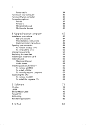
... 35 Turning off your computer 36 Connecting options 37 Printer 37 Network 38 Modem (optional) 39 Multimedia devices 40 4 Upgrading your computer 45 Installation precautions 47 ESD precautions 47 Preinstallation instructions 47 Post-installation instructions 48 Opening your computer 49 To remove the... additional memory 65 To remove a DIMM 65 To install a DIMM 66 To reconfigure your computer 67 Upgrading the CPU 68 To remove the CPU 68 To install the upgrade CPU 69 5 Software 71 PC-cillin 74 LDCM 75 NTI CD-Maker 2000 76 PowerDVD 77 BIOS utility ...
... 35 Turning off your computer 36 Connecting options 37 Printer 37 Network 38 Modem (optional) 39 Multimedia devices 40 4 Upgrading your computer 45 Installation precautions 47 ESD precautions 47 Preinstallation instructions 47 Post-installation instructions 48 Opening your computer 49 To remove the... additional memory 65 To remove a DIMM 65 To install a DIMM 66 To reconfigure your computer 67 Upgrading the CPU 68 To remove the CPU 68 To install the upgrade CPU 69 5 Software 71 PC-cillin 74 LDCM 75 NTI CD-Maker 2000 76 PowerDVD 77 BIOS utility ...
Veriton 3200 User Guide
Page 72
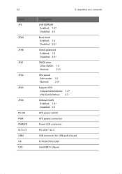
62 Label JP3 JPXA JPXB JPX1 JPX2 JPX3 JPX4 PS-ON PWR PWRLED SL1 to 3 USB2 U4 U10 4 Upgrading your computer Component LAN EEPROM Enabled: 1-2* Disabled: 2-3 Boot block Enabled: 1-2 Disabled: 2-3* Check password Enabled: 1-2 Disabled: 2-3* CMOS clear Clear CMOS: Normal: 1-2 2-3* CPU speed Safe mode: Normal: 1-2 2-3* Support CPU Coppermine/Celeron: 1-2* VIA (Cyrix)/Joshua: 2-3 Onboard LAN Enabled: 1-2* Disabled: 2-3 ATX power switch ATX power connector Power LED connector PCI slots 1 to 3 USB connector for USB-audio board FC-PGA CPU socket Intel 82815 Chipset
62 Label JP3 JPXA JPXB JPX1 JPX2 JPX3 JPX4 PS-ON PWR PWRLED SL1 to 3 USB2 U4 U10 4 Upgrading your computer Component LAN EEPROM Enabled: 1-2* Disabled: 2-3 Boot block Enabled: 1-2 Disabled: 2-3* Check password Enabled: 1-2 Disabled: 2-3* CMOS clear Clear CMOS: Normal: 1-2 2-3* CPU speed Safe mode: Normal: 1-2 2-3* Support CPU Coppermine/Celeron: 1-2* VIA (Cyrix)/Joshua: 2-3 Onboard LAN Enabled: 1-2* Disabled: 2-3 ATX power switch ATX power connector Power LED connector PCI slots 1 to 3 USB connector for USB-audio board FC-PGA CPU socket Intel 82815 Chipset

Veriton 3200 User Guide
Page 78
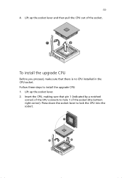
68 Upgrading the CPU 4 Upgrading your processor, you have removed the computer cover (see page 49). On the mainboard, locate the CPU mounted on page 47 when installing or removing a computer component. Remove the fan/heatsink from the socket. 3. Follow these steps to detach the metal bracket from the CPU. .... Insert a flat screwdriver into the fan/heatsink metal bracket, press down and pry the screwdriver outward to remove the CPU: 1. To remove the CPU Before you can replace or upgrade your computer Note: Observe the "Installation precautions" on the socket. 2.
68 Upgrading the CPU 4 Upgrading your processor, you have removed the computer cover (see page 49). On the mainboard, locate the CPU mounted on page 47 when installing or removing a computer component. Remove the fan/heatsink from the socket. 3. Follow these steps to detach the metal bracket from the CPU. .... Insert a flat screwdriver into the fan/heatsink metal bracket, press down and pry the screwdriver outward to remove the CPU: 1. To remove the CPU Before you can replace or upgrade your computer Note: Observe the "Installation precautions" on the socket. 2.
Veriton 3200 User Guide
Page 79
Insert the CPU, making sure that there is no CPU installed in the CPU socket. Follow these steps to lock the CPU into the socket. Press down the socket lever to install the upgrade CPU: 1. 69 4. To install the upgrade CPU Before you proceed, make sure that pin 1 (indicated by a notched corner) of the CPU connects to hole 1 of the socket. Lift up the socket lever and then pull the CPU out of the socket (the bottom right corner). Lift up the socket lever. 2.
Insert the CPU, making sure that there is no CPU installed in the CPU socket. Follow these steps to lock the CPU into the socket. Press down the socket lever to install the upgrade CPU: 1. 69 4. To install the upgrade CPU Before you proceed, make sure that pin 1 (indicated by a notched corner) of the CPU connects to hole 1 of the socket. Lift up the socket lever and then pull the CPU out of the socket (the bottom right corner). Lift up the socket lever. 2.
Veriton 3200 User Guide
Page 80
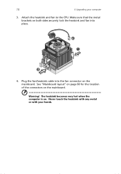
70 4 Upgrading your hands. Attach the heatsink and fan to the CPU. Warning! See "Mainboard layout" on page 60 for the location of the connectors on . Make sure that the metal brackets on both sides securely lock the heatsink and fan into the fan connector on the mainboard. The heatsink becomes very hot when the computer is on the mainboard. Never touch the heatsink with any metal or with your computer 3. Plug the fan/heatsink cable into place. 4.
70 4 Upgrading your hands. Attach the heatsink and fan to the CPU. Warning! See "Mainboard layout" on page 60 for the location of the connectors on . Make sure that the metal brackets on both sides securely lock the heatsink and fan into the fan connector on the mainboard. The heatsink becomes very hot when the computer is on the mainboard. Never touch the heatsink with any metal or with your computer 3. Plug the fan/heatsink cable into place. 4.


