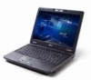
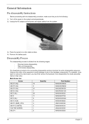
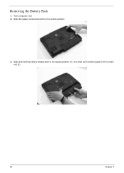
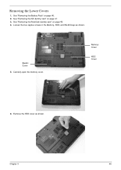
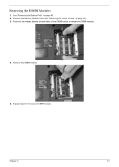
TravelMate 4730/4730G Service Guide
Page 7
...12 Lock Keys and embedded numeric keypad 12 Windows Keys 13 Hot Keys 14 Special Key 15 Using the System Utilities 16 Acer GridVista (dual-display compatible 16 Hardware Specifications and Configurations 18 System Utilities 25 BIOS Setup Utility 25 Navigating the BIOS Utility 25... General Information 44 Pre-disassembly Instructions 44 Disassembly Process 44 External Module Disassembly Process 45 External Modules Disassembly Flowchart 45 Removing the Battery Pack 46 Removing the SD dummy card 47 Removing the NewCard dummy card 48 Removing the Lower Covers 49 Removing the DIMM...
TravelMate 4730/4730G Service Guide
Page 12
...; 2.51 kg (5.53 lbs.) with 9-cell battery pack* Power subsystem • ACPI 3.0 • 48.8W 4400 mAh • 3-pin 65 W AC adapter* • 3-pin 90 W AC adapter* • Energy Star 4.0 Input Devices • 88-/89-/93-key keyboard • Touchpad pointing device I/O interface • Acer EasyPort IV connector • PC Card slot...
TravelMate 4730/4730G Service Guide
Page 19
Enable the computer to stay cool, even after prolonged use. Battery lock Memory compartment Hard disk bay Acer DASP (Disk Anti-Shock Protection) Ventilation slots and cooling fan Battery release latch Locks the battery in position. Chapter 1 9 Protects the hard disk drive from shocks and bumps (only for removal. Bottom View No. 1 2 3 4 5 6 7 Icon Item Battery bay Description Houses the computer's battery pack. Releases the battery for certain models). Houses the computer's main memory. Houses the computer's hard disk (secured with screws).
TravelMate 4730/4730G Service Guide
Page 20
...visible even when the computer cover is closed. Enables/disables the wireless function. 10 Chapter 1 Battery HDD Num Lock Caps Lock Indicates the computer's battery status. NOTE: 1. Indicates the computer's power status. Indicators The computer has several easy-to ... communication. Fully charged: The light shows green when in AC mode. Icon Function Empowering Technology Web browser Description Launch Acer Empowering Technology. (user-programmable) Internet browser (user-Programmable) Mail Email application (user-Programmable) Bluetooth communication switch Wireless ...
TravelMate 4730/4730G Service Guide
Page 32
... colors (RGB 6-bit) Min. 40 Typ. 45 Min. 10 Typ. 35 0 to +50 -20 to the USB port directly: Yes Battery Item Vendor & model name Battery Type Pack capacity Number of battery cell Package configuration Sanyo TM-2007A Li-Ion 4400mAh 6 3S2P Specification Sony TM-2007A Li-Ion 7200mAh 9 3S3P LCD 14.1" Item...
TravelMate 4730/4730G Service Guide
Page 33
... out or by hot key • HDD Local Stand-By mode by time out • LCD Local Stand-By mode by time out • Low battery alarm by beep • Auto-backlight off when LCD cover closed • Full ACPI 1.0B supported • LCD Auto-DIM mode by time out Chapter...
TravelMate 4730/4730G Service Guide
Page 47
... USB HDD) before you use the Phlash. Select Boot Menu to use the AC adaptor power supply when you use the Phlash utility. If the battery pack does not contain enough power to Memory).
TravelMate 4730/4730G Service Guide
Page 54
... that you must first remove the keyboard, then disassemble the inside assembly frame in the succeeding disassembly sections illustrate the entire disassembly sequence. Remove the battery pack. Place the system on a flat, stable surface. 4. Turn off the power to any of the hardware components. Observe the order of the sequence to...
TravelMate 4730/4730G Service Guide
Page 56
Slide and hold the battery release latch to the unlock position. 3. Removing the Battery Pack 1. Turn computer over. 2. Slide the battery lock/unlock latch to the release position (1), then slide out the battery pack from the main unit (2). 1 2 46 Chapter 3
TravelMate 4730/4730G Service Guide
Page 59
See "Removing the NewCard dummy card" on page 46. 2. Loosen the five captive screws in the Memory, HDD, and WLAN bays as shown. See "Removing the Battery Pack" on page 48. 4. See "Removing the SD dummy card" on page 47. 3. Remove the HDD cover as shown. Chapter 3 49 Removing the Lower Covers 1. Memory Cover HDD Cover 6. WLAN Cover 5. Carefully open the memory cover.
TravelMate 4730/4730G Service Guide
Page 61
Push out the release latches on page 49. 3. Chapter 3 51 Remove the DIMM module. 5. Removing the DIMM Modules 1. Remove the Memory Module cover See "Removing the Lower Covers" on both sides of the DIMM socket to release the DIMM module. 4. See "Removing the Battery Pack" on page 46. 2. Repeat steps for the second DIMM module.
TravelMate 4730/4730G Service Guide
Page 62
See "Removing the Lower Covers" on page 46. 2. Remove the adhesive tape and disconnect the antenna cables from the WLAN board. 4. Step WLAN Module Size M2*3 (NL) Quantity 2 Screw Type 52 Chapter 3 Removing the WLAN Module 1. See "Removing the Battery Pack" on page 49. 3. Remove the WLAN cover. Move the antenna cables away and remove the two screws on the WLAN board to release the WLAN board.
TravelMate 4730/4730G Service Guide
Page 64
NOTE: To prevent damage to clear the carrier. 54 Chapter 3 Removing the Hard Disk Drive Module 1. Remove the HDD holder by easing the sides outward to device, avoid pressing down on it or placing heavy objects on top of it. 4. Remove the HDD cover, See "Removing the Lower Covers" on page 46. 2. Use the mylar tab to slide and lift up the hard disk drive module to remove. See "Removing the Battery Pack" on page 49. 3.
TravelMate 4730/4730G Service Guide
Page 66
Remove the screw securing the ODD module. See "Removing the Lower Covers" on page 46. 2. Remove the Memory cover. Using a screw driver, push the ODD module through the chassis and pull to remove it from the main unit. 56 Chapter 3 See "Removing the Battery Pack" on page 49. 3. Step ODD Module Size M2.5*5(NL) Quantity 1 Screw Type 4. Removing the Optical Drive Module 1.
TravelMate 4730/4730G Service Guide
Page 69
... Type 3. Turn the computer over and open in the horizontal position to expose the Switch Cover. Lift the Switch Cover as shown. See "Removing the Battery Pack" on page 46. 2. Locate and remove the five securing screws as shown, rightside first. 5. Lift the Switch Cover clear of the chassis. Removing the...
TravelMate 4730/4730G Service Guide
Page 70
See "Removing the Switch Cover" on page 46. 2. Lift the keyboard as shown to release the FFC. 60 Chapter 3 Step Keyboard Size M2*3 Quantity 2 4. See "Removing the Battery Pack" on page 59. 3. Screw Type 5. Turn the keyboard over and pull back the securing latch to remove from the chassis. Remove the two screws securing the keyboard to the upper case. Removing the Keyboard 1.
TravelMate 4730/4730G Service Guide
Page 71
Chapter 3 61 See "Removing the Battery Pack" on page 60. 3. Removing the Power Board 1. Disconnect the Power Board cable from the Power Board. NOTE: The left hand securing screw is shared by the eKey Board. 6. Remove the two securing screws from the mainboard. 4. Remove the keyboard from the chassis. See "Removing the Keyboard" on page 46. 2.
TravelMate 4730/4730G Service Guide
Page 72
See "Removing the Keyboard" on page 46. 2. See "Removing the Battery Pack" on page 60. 3. Disconnect the Launch Board cable from the Launch Board. Screw Type 4. NOTE: The right hand securing screw is shared by the Power Board. 62 Chapter 3 Remove the two securing screws from the mainboard. Step Power Board Size M2*3 Quantity 2 Removing the Launch Board 1.
TravelMate 4730/4730G Service Guide
Page 75
See "Removing the Battery Pack" on page 52. 4. See "Removing the WLAN Module" on page 46. 2. Step LCD Module Size M2.5*8(NL) Quantity 2 Screw Type 6. Turn the computer over. See "Removing the Antenna" on page 49. 3. Remove the Lower Covers. See "Removing the Lower Covers" on page 63. 5. Chapter 3 65 Remove the Battery Pack. Remove the WLAN Module. Remove the Antenna. Disconnect the LCD cable from the bottom of the chassis. Removing the LCD Module 1. Remove the two securing screws from the top panel.
TravelMate 4730/4730G Service Guide
Page 77
See "Removing the LCD Module" on the bottom panel. Remove the sixteen screws on page 65. 3. Turn the computer over. See "Removing the Battery Pack" on page 46. 2. Step Upper Cover Size M2.5x9 Quantity 16 Screw Type Chapter 3 67 Removing the Upper Cover 1.