
AL512 Monitor Service Guide
Page 1
... 2 3. SPECIFICATIONS 2~4 3.1. PRODUCT SPECIFICATIONS 2 3.2. BLOCK DIAGRAM 8 6. MVZ 10 6.3. Audio (except for AL513 14 6.7. MAIN PCB TOP VIEW 18 9.2. AUDIO & IN PCB BOTTOM VIEW 23 9.7. TROUBLE SHOOTING FLOW CHART 26~28 10.1. EXPLODED VIEW AND PARTS LIST 5~7 4.1. EXPLODED VIEW PARTS LIST 6~7 5. MCU 11 6.4. WORKING THEOREM 16 8. CON PCB BOTTOM VIEW 21 9.5. NO DISPLAY 27 10.3. ADJUSTMENT CONDITIONS AND PRECAUTIONS 29 11.2. AL512/AL513 Service Manual TABLE OF CONTENTS PAGE 1. SAFETY PRECAUTIONS 1 1.2. AUDIO...
... 2 3. SPECIFICATIONS 2~4 3.1. PRODUCT SPECIFICATIONS 2 3.2. BLOCK DIAGRAM 8 6. MVZ 10 6.3. Audio (except for AL513 14 6.7. MAIN PCB TOP VIEW 18 9.2. AUDIO & IN PCB BOTTOM VIEW 23 9.7. TROUBLE SHOOTING FLOW CHART 26~28 10.1. EXPLODED VIEW AND PARTS LIST 5~7 4.1. EXPLODED VIEW PARTS LIST 6~7 5. MCU 11 6.4. WORKING THEOREM 16 8. CON PCB BOTTOM VIEW 21 9.5. NO DISPLAY 27 10.3. ADJUSTMENT CONDITIONS AND PRECAUTIONS 29 11.2. AL512/AL513 Service Manual TABLE OF CONTENTS PAGE 1. SAFETY PRECAUTIONS 1 1.2. AUDIO...
AL512 Monitor Service Guide
Page 2
... components read the parts list in this guide handy. Stop using replacement components rated for power input. ! PRECAUTION AND NOTICES 1.1. Do not place heavy objects on a ground principle that a user's safety comes first. WARNINGS: ! This monitor should be repaired by a service technacian. ! Before replacing any of this manual carefully. The use or installation may cause electric shock to human bodies, even when the power cord is manufactured...
... components read the parts list in this guide handy. Stop using replacement components rated for power input. ! PRECAUTION AND NOTICES 1.1. Do not place heavy objects on a ground principle that a user's safety comes first. WARNINGS: ! This monitor should be repaired by a service technacian. ! Before replacing any of this manual carefully. The use or installation may cause electric shock to human bodies, even when the power cord is manufactured...
AL512 Monitor Service Guide
Page 3
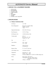
SERVICE TOOL & EQUIPMENT REQUIRED 1. SCREW DRIVER 5. DUMMY LOAD (5ohm/200W) 3. AL512/AL513 Service Manual 2. MULTIMETER 3. SPECIFICATIONS 3.1. PRODUCT SPECIFICATIONS LCD Panel 15.0" TFT Power Management Energy Star compliant VESA DPMS compatible < 3W Displayable Resolution XGA 1024× 768 (max.) Pixel Dimension 0.297× 0.297mm LCD Display Color 16.7M Color Max. (8bit) Viewing Angle CR≧10 Horizontal: -60°~+60° Vertical: -55°~+45° Tilt +90°, -5° Contrast Ratio Brightness 200 : 1 (min.) 350 : 1 (typ.) 200cd...
SERVICE TOOL & EQUIPMENT REQUIRED 1. SCREW DRIVER 5. DUMMY LOAD (5ohm/200W) 3. AL512/AL513 Service Manual 2. MULTIMETER 3. SPECIFICATIONS 3.1. PRODUCT SPECIFICATIONS LCD Panel 15.0" TFT Power Management Energy Star compliant VESA DPMS compatible < 3W Displayable Resolution XGA 1024× 768 (max.) Pixel Dimension 0.297× 0.297mm LCD Display Color 16.7M Color Max. (8bit) Viewing Angle CR≧10 Horizontal: -60°~+60° Vertical: -55°~+45° Tilt +90°, -5° Contrast Ratio Brightness 200 : 1 (min.) 350 : 1 (typ.) 200cd...
AL512 Monitor Service Guide
Page 5
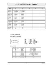
... V Border 0.000ms 0.000ms H/V Sync -/- +/+ Interlace No. D-SUB CONNECTOR D-SUB 15 PIN CONNECTOR 1 2345 6 7 8 9 10 11 12 13 14 15 1.R 2.G 3.B 4.NC 5.GND 6.GND 11.NC 7.GND 12.SDA 8.GND 13.H-SYNC 9. +5V 14.V-SYNC 10.GND 15.SCL SIGNAL LEVEL CONNECTOR R G B H V SDA SCL SIGNAL RED GREEN BLUE H/SYNC V/SYNC DDC1/2B DDC1/2B DESCRIPTION 0.7vp-p(VIDEO) 0.7vp-p(VIDEO) 0.7vp-p(VIDEO) TTL positive or negative TTL positive or negative TTL...
... V Border 0.000ms 0.000ms H/V Sync -/- +/+ Interlace No. D-SUB CONNECTOR D-SUB 15 PIN CONNECTOR 1 2345 6 7 8 9 10 11 12 13 14 15 1.R 2.G 3.B 4.NC 5.GND 6.GND 11.NC 7.GND 12.SDA 8.GND 13.H-SYNC 9. +5V 14.V-SYNC 10.GND 15.SCL SIGNAL LEVEL CONNECTOR R G B H V SDA SCL SIGNAL RED GREEN BLUE H/SYNC V/SYNC DDC1/2B DDC1/2B DESCRIPTION 0.7vp-p(VIDEO) 0.7vp-p(VIDEO) 0.7vp-p(VIDEO) TTL positive or negative TTL positive or negative TTL...
AL512 Monitor Service Guide
Page 7
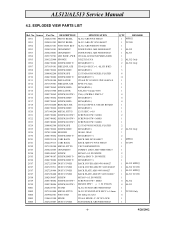
... SCREW,B OTW+ 2C09 2085740086 SCREW,B OTW+ 5B01 2028255701 STAND 5B02 2071963400 METAL FITTG 5B04 2039802301 FOOT PAD 5B05 2106653100 HINGE 5B06 2027255407 DUST COVER SPECIFICATION AL512 ABS 94V0 860027 AL513 ABS+PC 94V0 860027 AL512 ABS 94HB PS-7604B DOOR PANEL ABS 94HB 860027 DOOR PANEL ABS 94HB 860027 JT166AL LED LENS PMMA 94HB 36X23X3t EVA M3X8(BND T+) JT166L14 SECC t=1. 0(LCD...
... SCREW,B OTW+ 2C09 2085740086 SCREW,B OTW+ 5B01 2028255701 STAND 5B02 2071963400 METAL FITTG 5B04 2039802301 FOOT PAD 5B05 2106653100 HINGE 5B06 2027255407 DUST COVER SPECIFICATION AL512 ABS 94V0 860027 AL513 ABS+PC 94V0 860027 AL512 ABS 94HB PS-7604B DOOR PANEL ABS 94HB 860027 DOOR PANEL ABS 94HB 860027 JT166AL LED LENS PMMA 94HB 36X23X3t EVA M3X8(BND T+) JT166L14 SECC t=1. 0(LCD...
AL512 Monitor Service Guide
Page 8
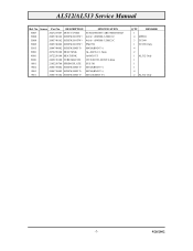
Source Part No. AL512/AL513 Service Manual Ref. DESCRIPTION 5B07 2027255607 DUST COVER 5B08 2085740162 SCREW,B OTW+ 5B08 2085740162 SCREW,B OTW+ 5B09 2085740202 SCREW,B OTW+ 5B15 2084740082 SCREW,BND T+ 9H01 2072258100 HEAT SINK 9H61 2072250100 HEAT SINK 9R81 2429150100 TUBE,SILICON 9S01 2105250700 SPRING PLATE 9S02 2084730082 SCREW,BND T+ 9S03 2084730082 SCREW,BND T+ 9S61 2084730102 SCREW,BND T+ SPECIFICATION STAND FRONT ABS 94HB 860027 4x16(+) SWRM-3 ZMC2...
Source Part No. AL512/AL513 Service Manual Ref. DESCRIPTION 5B07 2027255607 DUST COVER 5B08 2085740162 SCREW,B OTW+ 5B08 2085740162 SCREW,B OTW+ 5B09 2085740202 SCREW,B OTW+ 5B15 2084740082 SCREW,BND T+ 9H01 2072258100 HEAT SINK 9H61 2072250100 HEAT SINK 9R81 2429150100 TUBE,SILICON 9S01 2105250700 SPRING PLATE 9S02 2084730082 SCREW,BND T+ 9S03 2084730082 SCREW,BND T+ 9S61 2084730102 SCREW,BND T+ SPECIFICATION STAND FRONT ABS 94HB 860027 4x16(+) SWRM-3 ZMC2...
AL512 Monitor Service Guide
Page 9
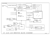
I601 TDA7053A/TDA7057 SPEAKER 15 inch LCD MONITOR BLOCK DIAGRAM 9/20/2002 -8- BLOCK DIAGRAM AC 110~220V INPUT SWITCHING POWER SUPPLY OSC. 12MHZ X101 12V for INVERTER 5V for system I103,I104,I110 5V to 3.3V 3.3V to 2.5V DC_EN DC-DC for PANEL POWER I108 AIC1341 Q105,Q106,...LCD CONTROLLER ADC+ SCALAR + T-CON SDA/SCL FROM D-SUB 15 PIN I102 24LC21 EEPROM DDC I100 24LC16B EEPROM EDID I2C BUS KEYPAD OSC. 12MHZ X100 I2C BUS I105 8051PLCC 48 Bits LCD FLAT PANEL STH1,LP,INV1,INV2 POL,STV1,CPV CPH1 BLT_ON BRIGHTNESS TO BACKLIGHT High Volt INVERTER OPTION VOLUMN CONTROL AUDIO IN AUDIO...
I601 TDA7053A/TDA7057 SPEAKER 15 inch LCD MONITOR BLOCK DIAGRAM 9/20/2002 -8- BLOCK DIAGRAM AC 110~220V INPUT SWITCHING POWER SUPPLY OSC. 12MHZ X101 12V for INVERTER 5V for system I103,I104,I110 5V to 3.3V 3.3V to 2.5V DC_EN DC-DC for PANEL POWER I108 AIC1341 Q105,Q106,...LCD CONTROLLER ADC+ SCALAR + T-CON SDA/SCL FROM D-SUB 15 PIN I102 24LC21 EEPROM DDC I100 24LC16B EEPROM EDID I2C BUS KEYPAD OSC. 12MHZ X100 I2C BUS I105 8051PLCC 48 Bits LCD FLAT PANEL STH1,LP,INV1,INV2 POL,STV1,CPV CPH1 BLT_ON BRIGHTNESS TO BACKLIGHT High Volt INVERTER OPTION VOLUMN CONTROL AUDIO IN AUDIO...
AL512 Monitor Service Guide
Page 17
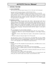
... panel data bus, Start Pulse(STH1) and Clock (CLKH), Polarity(POL)/Latch pulse(LP) for source driver IC, Start pulse(STV1) and Clock(CLKV) for gate driver IC, and Data inversion control(HMSO/HMSE) for odd/even pixel bus and the power supply (+3.2V, +3.45V,+9.2V, +18Vand-6V) for optimal image quality 4. It consists of AC voltage output. Automatically calibrate for the panel. C. AL512/513 Service Manual...
... panel data bus, Start Pulse(STH1) and Clock (CLKH), Polarity(POL)/Latch pulse(LP) for source driver IC, Start pulse(STV1) and Clock(CLKV) for gate driver IC, and Data inversion control(HMSO/HMSE) for odd/even pixel bus and the power supply (+3.2V, +3.45V,+9.2V, +18Vand-6V) for optimal image quality 4. It consists of AC voltage output. Automatically calibrate for the panel. C. AL512/513 Service Manual...
AL512 Monitor Service Guide
Page 27
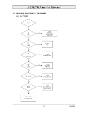
N 5V on C314,C319 Y 9.2V on C308 Y 18V on F102 Y -6V on C101 Y I101 is Failed? TROUBLE SHOOTING FLOW CHART 10.1. AL512/513 Service Manual 10. NO POWER Start 5V on F103 Y Check 3~4V Q107,C315,I108 Check N D804,D807, I801,I802,I803 D801,F801 Replace Y I101 N Check Q101,I107,Q114 N Check L111,D203, I108,Q106 N Check Q108,I109,F102 N Check D201,D202,F103, C302,Q105,I106 -26- 9/20/2002
N 5V on C314,C319 Y 9.2V on C308 Y 18V on F102 Y -6V on C101 Y I101 is Failed? TROUBLE SHOOTING FLOW CHART 10.1. AL512/513 Service Manual 10. NO POWER Start 5V on F103 Y Check 3~4V Q107,C315,I108 Check N D804,D807, I801,I802,I803 D801,F801 Replace Y I101 N Check Q101,I107,Q114 N Check L111,D203, I108,Q106 N Check Q108,I109,F102 N Check D201,D202,F103, C302,Q105,I106 -26- 9/20/2002

AL512 Monitor Service Guide
Page 28
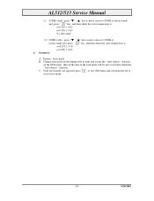
... ? Check I/P signal is Yes connect OK ? AL512/513 Service Manual 10.2. Change Inverter Check I001 MVZ if RST Pin#155 have signal Change I001 LCD controller IC Yes Check panel Powers VDDD=3.3V VDDA=9.2V VDDG=18V VEEG=-6V Yes Change LCD panel -27- 9/20/2002 Yes No Check uP I105 pin#24 send reset ? Yes Change X101 Check J105,J106 No data bus have reset pulse ? NO DISPLAY No Display Check Power region Dark Amber Check LED Color Check IO cable...
... ? Check I/P signal is Yes connect OK ? AL512/513 Service Manual 10.2. Change Inverter Check I001 MVZ if RST Pin#155 have signal Change I001 LCD controller IC Yes Check panel Powers VDDD=3.3V VDDA=9.2V VDDG=18V VEEG=-6V Yes Change LCD panel -27- 9/20/2002 Yes No Check uP I105 pin#24 send reset ? Yes Change X101 Check J105,J106 No data bus have reset pulse ? NO DISPLAY No Display Check Power region Dark Amber Check LED Color Check IO cable...

AL512 Monitor Service Guide
Page 29
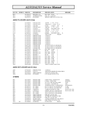
Check R602 & R605 is OK ? NO SOUND Speaker No Sound Earphone no sound Check Volume No Control Pin 1&7 Voltage 0.4~0.85V ? Check if Speaker is OK ? and Check Pin 1&7 Voltage >0.4V No Yes Check Q010 Collector has PWM output ? Yes Check if I601 Pin 4 No Vp=12V ? AL512/513 Service Manual 10.3. Yes Yes Change I601 TDA7057AQ Yes -28- 9/20/2002 Yes Adjust OSD Volume control to Max.
Check R602 & R605 is OK ? NO SOUND Speaker No Sound Earphone no sound Check Volume No Control Pin 1&7 Voltage 0.4~0.85V ? Check if Speaker is OK ? and Check Pin 1&7 Voltage >0.4V No Yes Check Q010 Collector has PWM output ? Yes Check if I601 Pin 4 No Vp=12V ? AL512/513 Service Manual 10.3. Yes Yes Change I601 TDA7057AQ Yes -28- 9/20/2002 Yes Adjust OSD Volume control to Max.
AL512 Monitor Service Guide
Page 30
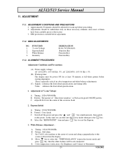
This is needed before adjustment. 11.2. Adjustment of " Shut down windows" or Full screen pixel ON/OFF pattern. B. Eeprom Initial: A. Pattern : Cross hatch. C. B. E. AL512/513 Service Manual 11. Eeprom Initial 3. D. Timing : 1024x768@60Hz. Set CA110 color analizer at the center of screen and along a perpendicular to the screen at the factory. 3. D. Adjustments should be auto dadjusted. Geometry DESIGNATION R124 (VCOM ADJ) Function Key Function Key Function Key...
This is needed before adjustment. 11.2. Adjustment of " Shut down windows" or Full screen pixel ON/OFF pattern. B. Eeprom Initial: A. Pattern : Cross hatch. C. B. E. AL512/513 Service Manual 11. Eeprom Initial 3. D. Timing : 1024x768@60Hz. Set CA110 color analizer at the center of screen and along a perpendicular to the screen at the factory. 3. D. Adjustments should be auto dadjusted. Geometry DESIGNATION R124 (VCOM ADJ) Function Key Function Key Function Key...
AL512 Monitor Service Guide
Page 31
... in turns and excute the "Auto Adjust " function on the OSD menu , then all of the each mode will be auto saved after finish the "Auto Adjust " function. C. Until all the data of modes are agjusted, press " 1 " to exit OSD menu and switch power off to 9300K at factory mode and press " 2 " key, and then check the color temperature is x=0.283 ± 0.03 y=0.298 ± 0.03 4. Geometry: A. AL512/513 Service Manual (1) 6500K...
... in turns and excute the "Auto Adjust " function on the OSD menu , then all of the each mode will be auto saved after finish the "Auto Adjust " function. C. Until all the data of modes are agjusted, press " 1 " to exit OSD menu and switch power off to 9300K at factory mode and press " 2 " key, and then check the color temperature is x=0.283 ± 0.03 y=0.298 ± 0.03 4. Geometry: A. AL512/513 Service Manual (1) 6500K...
AL512 Monitor Service Guide
Page 39
AL512/AL513 Service Manual LOC NO. R841 T801 U801 SOURCE PART NO. 2233447195 2374208200 2202121101 DESCRIPTION RES,CBN 1/4 S XFORMER,POWR PC BOARD AUDIO P.C.BOARD (AL512... POWER CORD POWER CORD POWER CORD POWER CORD POWER CORD I/O CABLE I/O CABLE CORD RCA CORD RCA FFC CABLE FFC CABLE WIRE HARNESS WIRE HARNESS WIRE HARNESS SOCKET,ASSY WIRE HARNESS INVERTER SPECIFICATION...AUDIO IN 94V0 23*30 CHINA WALL 1.5M RAL7035 E WALL 1.83M(71922) SVT 18/3 1.8M USA WALL KDS UK WALL 1.83M GE96750 AUSTRALIA WALL 1.83M GE96750 D15/C13 20276(3+6)1.5M GE96750 D15/C13 20276(3+6)1.83M 96750 3.5φPLUG...
AL512/AL513 Service Manual LOC NO. R841 T801 U801 SOURCE PART NO. 2233447195 2374208200 2202121101 DESCRIPTION RES,CBN 1/4 S XFORMER,POWR PC BOARD AUDIO P.C.BOARD (AL512... POWER CORD POWER CORD POWER CORD POWER CORD POWER CORD I/O CABLE I/O CABLE CORD RCA CORD RCA FFC CABLE FFC CABLE WIRE HARNESS WIRE HARNESS WIRE HARNESS SOCKET,ASSY WIRE HARNESS INVERTER SPECIFICATION...AUDIO IN 94V0 23*30 CHINA WALL 1.5M RAL7035 E WALL 1.83M(71922) SVT 18/3 1.8M USA WALL KDS UK WALL 1.83M GE96750 AUSTRALIA WALL 1.83M GE96750 D15/C13 20276(3+6)1.5M GE96750 D15/C13 20276(3+6)1.83M 96750 3.5φPLUG...

AL512 User Guide
Page 5
... determine it 's not properly installed and used to meet the emission level limits. If this monitor, a high-resolution multi-scan color monitor. Connect the monitor into an outlet on a circuit different from each other. ! Note: If necessary, shielded interface cables and AC power cord must use a grounded power supply cord and the provided shielded video interface cable with the limits for purchasing this monitor does cause serious interference...
... determine it 's not properly installed and used to meet the emission level limits. If this monitor, a high-resolution multi-scan color monitor. Connect the monitor into an outlet on a circuit different from each other. ! Note: If necessary, shielded interface cables and AC power cord must use a grounded power supply cord and the provided shielded video interface cable with the limits for purchasing this monitor does cause serious interference...
AL512 User Guide
Page 7
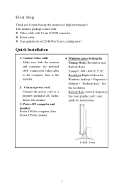
... Windows desktop > Porperties > Settings > "Desktop Area". Set the resolution. Connect video cable Make sure both the monitor and computer are powered OFF. Connect the video cable to the computer, then to the monitor. 3. Refresh Rate (vertical frequency) See your graphic card's user guide for purchasing this monitor of high performance! First Step Thank you for instructions. This monitor package comes with: # Video cable with 15 pin D-SUB connector. # Power cable. # User guidebook or CD-ROM (You're reading now) Quick Installation 1. Connect power cord Connect the power cord...
... Windows desktop > Porperties > Settings > "Desktop Area". Set the resolution. Connect video cable Make sure both the monitor and computer are powered OFF. Connect the video cable to the computer, then to the monitor. 3. Refresh Rate (vertical frequency) See your graphic card's user guide for purchasing this monitor of high performance! First Step Thank you for instructions. This monitor package comes with: # Video cable with 15 pin D-SUB connector. # Power cable. # User guidebook or CD-ROM (You're reading now) Quick Installation 1. Connect power cord Connect the power cord...
AL512 User Guide
Page 9
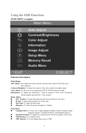
... display the resolution notice about best quality of the video. * OSD Position: To set OSD position. * OSD Timeout: To set the disappearance time of the video and the back-light current . Information: To display the Horizontal / Vertical frequency ,Pixel clock, Resolution ,Model number and Serial No. Contrast /Brightness: To adjust the contrast of OSD. 3 of the video. * H. Image Adjust: * H./V. Position: To adjust the horizontal and vertical position of the monitor. Color Adjust: To select the color temperature 6500°K, 9300°K and user settings. Using the OSD Functions...
... display the resolution notice about best quality of the video. * OSD Position: To set OSD position. * OSD Timeout: To set the disappearance time of the video and the back-light current . Information: To display the Horizontal / Vertical frequency ,Pixel clock, Resolution ,Model number and Serial No. Contrast /Brightness: To adjust the contrast of OSD. 3 of the video. * H. Image Adjust: * H./V. Position: To adjust the horizontal and vertical position of the monitor. Color Adjust: To select the color temperature 6500°K, 9300°K and user settings. Using the OSD Functions...
AL512 User Guide
Page 10
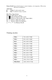
... disable the volume of contrast, brightness, color temperature, OSD position, OSD timeout and Sharpness Audio Menu: ! Timing modes VESA VESA MAC VESA VESA VESA VESA VESA MAC VESA VESA VESA/MAC 720 x 400 @ 70HZ 640 x 480 @ 60HZ 640 x 480 @ 67HZ 640 x 480 @ 75HZ 800 x 600 @ 56HZ 800 x 600 @ 60HZ 800 x 600 @ 72HZ 800 x 600 @ 75HZ 832 x 624 @ 75HZ 1024 x 768 @ 60HZ 1024 x 768 @ 70HZ 1024 x 768 @ 75 Hz 4 Volume: For adjust speaker output. ! Memory Recall: Restore default settings of speaker...
... disable the volume of contrast, brightness, color temperature, OSD position, OSD timeout and Sharpness Audio Menu: ! Timing modes VESA VESA MAC VESA VESA VESA VESA VESA MAC VESA VESA VESA/MAC 720 x 400 @ 70HZ 640 x 480 @ 60HZ 640 x 480 @ 67HZ 640 x 480 @ 75HZ 800 x 600 @ 56HZ 800 x 600 @ 60HZ 800 x 600 @ 72HZ 800 x 600 @ 75HZ 832 x 624 @ 75HZ 1024 x 768 @ 60HZ 1024 x 768 @ 70HZ 1024 x 768 @ 75 Hz 4 Volume: For adjust speaker output. ! Memory Recall: Restore default settings of speaker...
AL512 User Guide
Page 12
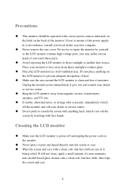
.... Cleaning the LCD monitor + Make sure the LCD monitor is clean and free of the power supply in a well ventilated area. Place your monitor to face away from magnets, motors, transformers, speakers, and TV sets. + If smoke, abnormal noise, or strange odor is present, immediately switch off the monitor and call your dealer or service center. + Do not push or scratch the screen with anything on the LCD monitor...
.... Cleaning the LCD monitor + Make sure the LCD monitor is clean and free of the power supply in a well ventilated area. Place your monitor to face away from magnets, motors, transformers, speakers, and TV sets. + If smoke, abnormal noise, or strange odor is present, immediately switch off the monitor and call your dealer or service center. + Do not push or scratch the screen with anything on the LCD monitor...
AL512 User Guide
Page 13
Troubleshooting + No power 1. If the monitor LED light color is orange, please check it securely connected. Make sure your computer is tightly secured to the LCD monitor. + Power on . Check the video cable to make sure it goes into the power management state or not. + Wrong color 1. Loose or broken pins in the back of the computer. 2. Adjust brightness and contrast. 3. Make sure power botton (or switch) is securely connected to the video output port in the cable connector could cause...
Troubleshooting + No power 1. If the monitor LED light color is orange, please check it securely connected. Make sure your computer is tightly secured to the LCD monitor. + Power on . Check the video cable to make sure it goes into the power management state or not. + Wrong color 1. Loose or broken pins in the back of the computer. 2. Adjust brightness and contrast. 3. Make sure power botton (or switch) is securely connected to the video output port in the cable connector could cause...

