
AL1911 Service Guide
Page 1
......41 1 AL1911 TFT LCD MONITOR CONTENTS 1. VK906 Control Panel Board...24 4.1 Description...24 4.2 Connector and Switch Locations...24 4.3 Connector type...24 4.4 Connector pin Assignment ...24 4.5 Switch definition...25 4.6 LED definition...25 5. POWER SUPPLY (VI-902) ...26 5.1 Electrical specification ...26 5.2 Pin Assignments...27 6. VM-902 AUDIO BOARD...28 6.1 Description...28 6.2 Connector Locations...28 7. VL-901 DISPLAY CONTROL BOARD 19 3.1 Description...19 3.2 Features...19 3.3 Block Diagram...19 3.4 Connector Locations...21 3.5 Connector Type...21 3.6 Connector pin assignment...
......41 1 AL1911 TFT LCD MONITOR CONTENTS 1. VK906 Control Panel Board...24 4.1 Description...24 4.2 Connector and Switch Locations...24 4.3 Connector type...24 4.4 Connector pin Assignment ...24 4.5 Switch definition...25 4.6 LED definition...25 5. POWER SUPPLY (VI-902) ...26 5.1 Electrical specification ...26 5.2 Pin Assignments...27 6. VM-902 AUDIO BOARD...28 6.1 Description...28 6.2 Connector Locations...28 7. VL-901 DISPLAY CONTROL BOARD 19 3.1 Description...19 3.2 Features...19 3.3 Block Diagram...19 3.4 Connector Locations...21 3.5 Connector Type...21 3.6 Connector pin assignment...
AL1911 Service Guide
Page 3
... also supports VESA DPMS power management and plug & play function. 1. There is a build-in stereo audio amplifier with volume control to provide a performance oriented product with no radiation. INTRODUCTION 1.1 Scope This specification defines the requirements for the 19" MICRO-PROCESSOR based Multimode supported high resolution color LCD monitor, This monitor can be directly connected to general 15 pin D-sub VGA connector, eliminates the requirement of speakers. 1.2 Description The LCD monitor is...
... also supports VESA DPMS power management and plug & play function. 1. There is a build-in stereo audio amplifier with volume control to provide a performance oriented product with no radiation. INTRODUCTION 1.1 Scope This specification defines the requirements for the 19" MICRO-PROCESSOR based Multimode supported high resolution color LCD monitor, This monitor can be directly connected to general 15 pin D-sub VGA connector, eliminates the requirement of speakers. 1.2 Description The LCD monitor is...
AL1911 Service Guide
Page 4
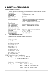
... settings User brightness control: User contrast control: User red/white balance, Green/white balance and Blue/white balance control: Power input : Ambient temperature : Analog input mode : 225 lux 50 cm in x 2.54 lb = kg x 2.2 degrees F = [°C x 1.8] + 32 degrees C = [°F - 32]/1.8 u' = 4x/(-2x + 12y + 3) v' = 9y/(-2x + 12y + 3) x = (27u'/4)/[(9u'/2) - 12v' + 9] y = (3v')/[(9u'/2) - 12v' + 9] nits = cd/(m2) = Ft-L x 3.426 lux = foot-candle x 10.76 2.2 LCD monitor General specification Panel Type : 19 " active matrix color TFT LCD 1). FUJITSU FLC48SXC8V-10 Display size...
... settings User brightness control: User contrast control: User red/white balance, Green/white balance and Blue/white balance control: Power input : Ambient temperature : Analog input mode : 225 lux 50 cm in x 2.54 lb = kg x 2.2 degrees F = [°C x 1.8] + 32 degrees C = [°F - 32]/1.8 u' = 4x/(-2x + 12y + 3) v' = 9y/(-2x + 12y + 3) x = (27u'/4)/[(9u'/2) - 12v' + 9] y = (3v')/[(9u'/2) - 12v' + 9] nits = cd/(m2) = Ft-L x 3.426 lux = foot-candle x 10.76 2.2 LCD monitor General specification Panel Type : 19 " active matrix color TFT LCD 1). FUJITSU FLC48SXC8V-10 Display size...
AL1911 Service Guide
Page 5
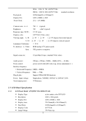
... with LED select (up, down) adjustment (+,-) Interface frequency Ÿ Horizontal Frequency 24KHz --80KHz Ÿ Vertical Frequency 56Hz ----75Hz Plug & play : Support VESA DDC2B functions Power Input voltage : Single phase, 50/60HZ, 100VAC to 240VAC ±10% Total output power : 55 Watt max. 2.3 LCD Panel Specification 2.3.1 LCD Panel Model (FUJITSU FLC48SXC8V-10) • Display Type • Resolution • Display Dot • Display Area • Pixel Pitch • Display Color • Lamp Voltage active matrix color TFT LCD 1280 x 1024 pixels 1280 x (RGB...
... with LED select (up, down) adjustment (+,-) Interface frequency Ÿ Horizontal Frequency 24KHz --80KHz Ÿ Vertical Frequency 56Hz ----75Hz Plug & play : Support VESA DDC2B functions Power Input voltage : Single phase, 50/60HZ, 100VAC to 240VAC ±10% Total output power : 55 Watt max. 2.3 LCD Panel Specification 2.3.1 LCD Panel Model (FUJITSU FLC48SXC8V-10) • Display Type • Resolution • Display Dot • Display Area • Pixel Pitch • Display Color • Lamp Voltage active matrix color TFT LCD 1280 x 1024 pixels 1280 x (RGB...
AL1911 Service Guide
Page 10
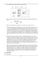
...Display the background only at level Gbkg. Turn on each box at the center point of Btgt (without Btgt present.). Look for the case with the source box (Bsrc) turned on the source box Bsrc. That is the shadowing source...Display Btgt determined in the shadow path. Again measure at a time. Turn off for the actual measurement. ♦ The target box point (Btgt) will be measuring the shadowing level, Lsh. 2.4 Input Signals 2.4.1 Video input 10 Use... (colors),first set to its proper level, measure the luminance (or color). Note 8) Definition of Crosstalk (Refer to the VESA STD...
...Display the background only at level Gbkg. Turn on each box at the center point of Btgt (without Btgt present.). Look for the case with the source box (Bsrc) turned on the source box Bsrc. That is the shadowing source...Display Btgt determined in the shadow path. Again measure at a time. Turn off for the actual measurement. ♦ The target box point (Btgt) will be measuring the shadowing level, Lsh. 2.4 Input Signals 2.4.1 Video input 10 Use... (colors),first set to its proper level, measure the luminance (or color). Note 8) Definition of Crosstalk (Refer to the VESA STD...
AL1911 Service Guide
Page 11
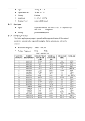
... • Amplitude • Display Color Analog R, G, B. 75 ohm +/- 2% Positive 0 - 0.7 +/- 0.05 Vp same as LCD panel 2.4.2 Sync input • Signal • Polarity separate horizontal and vertical sync, or composite sync which are TTL compatible positive and negative. 2.4.3 Interface frequency The following frequency range is generalized by supported timing. If the entered mode does not match the supported timing the display optimization will not be assured. • Horizontal Frequency 24KHz --80KHz • Vertical Frequency 56Hz ---------75Hz DISPLAY MODES MONITOR MODE NO...
... • Amplitude • Display Color Analog R, G, B. 75 ohm +/- 2% Positive 0 - 0.7 +/- 0.05 Vp same as LCD panel 2.4.2 Sync input • Signal • Polarity separate horizontal and vertical sync, or composite sync which are TTL compatible positive and negative. 2.4.3 Interface frequency The following frequency range is generalized by supported timing. If the entered mode does not match the supported timing the display optimization will not be assured. • Horizontal Frequency 24KHz --80KHz • Vertical Frequency 56Hz ---------75Hz DISPLAY MODES MONITOR MODE NO...
AL1911 Service Guide
Page 15
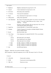
...; Exit: Brightness adjustment, the range from 0 to 100. message. Current mode vertical frequency±1Hz. Contrast adjustment, the range from 0 to +48, but some modes the range will automatically adjust size, position, clock and phase. Red signal gain by user defined. Set CIE coordinate at 6500°K color temperature. Exit OSD menu function. Vertical position adjustment. Focus adjustment, the range from 0 to 100. When auto start, it shows "Auto Adjusting... ." The max range from 0 to finish. Blue signal gain by user defined. Set CIE coordinate...
...; Exit: Brightness adjustment, the range from 0 to 100. message. Current mode vertical frequency±1Hz. Contrast adjustment, the range from 0 to +48, but some modes the range will automatically adjust size, position, clock and phase. Red signal gain by user defined. Set CIE coordinate at 6500°K color temperature. Exit OSD menu function. Vertical position adjustment. Focus adjustment, the range from 0 to 100. When auto start, it shows "Auto Adjusting... ." The max range from 0 to finish. Blue signal gain by user defined. Set CIE coordinate...

AL1911 Service Guide
Page 16
... "No Signal" and enter power saving mode. 2.6 White Color Temperature White color temperature is maximum setting for this mode whenever encounter this mode and switch to optimized condition automatically for panel. Target of user color should follow "Microsoft Windows Color Quality Specification for Liquid Crystal Display OEM's". (http://www.microsoft.com/hwdev/tech/color/ColorTest.asp) 16 User should be user which is 4 preset as 9300, 7500,6500 and User, Default value of color setting Color Color Coordinate Temp...
... "No Signal" and enter power saving mode. 2.6 White Color Temperature White color temperature is maximum setting for this mode whenever encounter this mode and switch to optimized condition automatically for panel. Target of user color should follow "Microsoft Windows Color Quality Specification for Liquid Crystal Display OEM's". (http://www.microsoft.com/hwdev/tech/color/ColorTest.asp) 16 User should be user which is 4 preset as 9300, 7500,6500 and User, Default value of color setting Color Color Coordinate Temp...
AL1911 Service Guide
Page 19
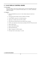
... convert the analog RGB signals from standard VGA display card to optimum LCD timing signals so as to construct a high display quality LCD monitor. 3.2 Features • On board embedded micro-processor to detect display timings and control user functions. • Using Genesis gm5120 design to generate optimum LCD timings. 2 • Using E PROM to memorize every adjusted parameter. • support up to 22 display modes from VGA to SXGA. • Offer full screen expansion function...
... convert the analog RGB signals from standard VGA display card to optimum LCD timing signals so as to construct a high display quality LCD monitor. 3.2 Features • On board embedded micro-processor to detect display timings and control user functions. • Using Genesis gm5120 design to generate optimum LCD timings. 2 • Using E PROM to memorize every adjusted parameter. • support up to 22 display modes from VGA to SXGA. • Offer full screen expansion function...
AL1911 Service Guide
Page 24
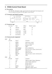
... Signal MUTE LED-Y LED-G GND KEY-POWER KEY-DOWN KEY-R KEY-L KEY-UP GND 4.4.2 J6 Pin NO. 1 2 3 4 5 6 Signal +5V VR L+ LMUTE HP-S Maker E&T E&T ACER ACER SC Number of pins 10 11 2 2 9 Comment Audio mute control Power saving mode Monitor is ON GND Power ON/OFF key Function select counter-clockwise key Adjust up key Adjust down key Function select counter-clockwise key GND Comment VDD for Audio Volume Adjustment Audio Volume Adjustment Speaker Out L + Speaker...
... Signal MUTE LED-Y LED-G GND KEY-POWER KEY-DOWN KEY-R KEY-L KEY-UP GND 4.4.2 J6 Pin NO. 1 2 3 4 5 6 Signal +5V VR L+ LMUTE HP-S Maker E&T E&T ACER ACER SC Number of pins 10 11 2 2 9 Comment Audio mute control Power saving mode Monitor is ON GND Power ON/OFF key Function select counter-clockwise key Adjust up key Adjust down key Function select counter-clockwise key GND Comment VDD for Audio Volume Adjustment Audio Volume Adjustment Speaker Out L + Speaker...

AL1911 Service Guide
Page 26
POWER SUPPLY (VI-902) 5.1 Electrical specification 5.1.1 AC/DC CKT: 1. Efficiency: 75% Min. 5. Dynamic Load Regulation: Less than +/- 5% * 0% ~ 100% or 100% ~ 50% load change of any DC output @ 50% duty of +5Vdc: +5.02 ~ 5.05V 16. Output setting voltage of 1Khz 13. Hold Up Time: 20mS Min. @ full load & 100Vac input condition (@Normal working loading) 7. MAX. +5Vdc (Vcc) +-5% 0.05A 1.4A...
POWER SUPPLY (VI-902) 5.1 Electrical specification 5.1.1 AC/DC CKT: 1. Efficiency: 75% Min. 5. Dynamic Load Regulation: Less than +/- 5% * 0% ~ 100% or 100% ~ 50% load change of any DC output @ 50% duty of +5Vdc: +5.02 ~ 5.05V 16. Output setting voltage of 1Khz 13. Hold Up Time: 20mS Min. @ full load & 100Vac input condition (@Normal working loading) 7. MAX. +5Vdc (Vcc) +-5% 0.05A 1.4A...

AL1911 Service Guide
Page 27
...=13V,ILAMP= 7.5mA - 750 3 Luminance 4 Brightness adjustable range Bmax Center of screen, 7mA for Open 13 Lamp Protection /each lamp 14 Audible Noise Ts Topen Vin=13V, ON/OFF=0V Vin=13V, each lamp. 240 300 Minimum Luminance ÷ Maximum Luminance - 40 5 Working Frequency Fo 50 55 6 Lamp Current ILAMP 7.5 7.7 7 Backlight ON/OFF Control Brightness control 8 range(positive adjustment) 9 Lamp Current Balance ON OFF...
...=13V,ILAMP= 7.5mA - 750 3 Luminance 4 Brightness adjustable range Bmax Center of screen, 7mA for Open 13 Lamp Protection /each lamp 14 Audible Noise Ts Topen Vin=13V, ON/OFF=0V Vin=13V, each lamp. 240 300 Minimum Luminance ÷ Maximum Luminance - 40 5 Working Frequency Fo 50 55 6 Lamp Current ILAMP 7.5 7.7 7 Backlight ON/OFF Control Brightness control 8 range(positive adjustment) 9 Lamp Current Balance ON OFF...
AL1911 User Guide
Page 1
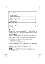
... 3 Connecting the AC Power...3 Connecting the Audio Cable ...3 Setting Up the LCD Monitor...4 Power Management System ...4 Chapter 2 Display Controls 4 User Controls ...4 Adjusting the Monitor's Display...4 Function Description ...5 Chapter 3 Technical Information 7 Specifications ...7 Standard Timing Table...9 Troubleshooting ...9 Preface This manual is designed to assist users in this document is required in accordance with the limits for help. Canadian DOC Notice This Class B digital apparatus meets all requirements of the manufacturer. NOTE A shielded-type signal cord is...
... 3 Connecting the AC Power...3 Connecting the Audio Cable ...3 Setting Up the LCD Monitor...4 Power Management System ...4 Chapter 2 Display Controls 4 User Controls ...4 Adjusting the Monitor's Display...4 Function Description ...5 Chapter 3 Technical Information 7 Specifications ...7 Standard Timing Table...9 Troubleshooting ...9 Preface This manual is designed to assist users in this document is required in accordance with the limits for help. Canadian DOC Notice This Class B digital apparatus meets all requirements of the manufacturer. NOTE A shielded-type signal cord is...
AL1911 User Guide
Page 2
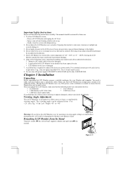
... a non-solvent cleaning solution onto a rag. -- You need a stable and clean surface near a window. Viewing Angle Adjustment The LCD Monitor is designed to allow users to rain. * LCD Monitor or the case is damaged. 7. Power off LCD Monitor and unplug the AC Cord. -- Do not place the LCD Monitor near a wall power outlet. Make sure that the following items were included in damaging the Monitor and Monitor stand. Important Safety Instructions Please read the...
... a non-solvent cleaning solution onto a rag. -- You need a stable and clean surface near a window. Viewing Angle Adjustment The LCD Monitor is designed to allow users to rain. * LCD Monitor or the case is damaged. 7. Power off LCD Monitor and unplug the AC Cord. -- Do not place the LCD Monitor near a wall power outlet. Make sure that the following items were included in damaging the Monitor and Monitor stand. Important Safety Instructions Please read the...
AL1911 User Guide
Page 3
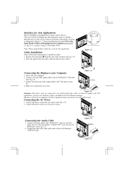
... your Computer 1. Power off -the-shelf video cable in Figure 1-3. Connect the power cord to your computer. 2. Make sure connections are secure. Connect the power cord to Fig.1-2. Note :Please using Ø 4mm x 8mm (L) screw for Arm Applications Before installing to mounting device, please refer to an AC power source. These specifications meet the VESA Flat Panel Monitor Physical Mounting Interface Standard (paragraphs 2.1 and 2.1.3, version 1, dated 13 November 1997). Connecting the Audio Cable 1. Remove the back panel n from...
... your Computer 1. Power off -the-shelf video cable in Figure 1-3. Connect the power cord to your computer. 2. Make sure connections are secure. Connect the power cord to Fig.1-2. Note :Please using Ø 4mm x 8mm (L) screw for Arm Applications Before installing to mounting device, please refer to an AC power source. These specifications meet the VESA Flat Panel Monitor Physical Mounting Interface Standard (paragraphs 2.1 and 2.1.3, version 1, dated 13 November 1997). Connecting the Audio Cable 1. Remove the back panel n from...
AL1911 User Guide
Page 4
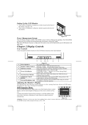
... for OSD (On Screen Display) menu selection. 6 Adjustment Control Buttons Press the left button to decrease the OSD setting and press the right button to switch the monitor ON/OFF. 4 Power-On Indicator LED lights Green color --- Turn the knob clock wise. The VESA DPMS provides four power saving modes through the entire menu items, then press Adjustment Control buttons to select among functions shown on all LCD Monitor functions control and indicator: 1 Stereo Speakers Figure 2-1 PC Audio Stereo output. 2 Speaker Volume Control 3 Soft Power Switch Increase Volume - Turn...
... for OSD (On Screen Display) menu selection. 6 Adjustment Control Buttons Press the left button to decrease the OSD setting and press the right button to switch the monitor ON/OFF. 4 Power-On Indicator LED lights Green color --- Turn the knob clock wise. The VESA DPMS provides four power saving modes through the entire menu items, then press Adjustment Control buttons to select among functions shown on all LCD Monitor functions control and indicator: 1 Stereo Speakers Figure 2-1 PC Audio Stereo output. 2 Speaker Volume Control 3 Soft Power Switch Increase Volume - Turn...
AL1911 User Guide
Page 5
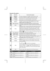
... coordinate color temperature to 6500°K Sets the settings to a by user defined CIE 5 Please see the diagram below for text. The recall function will take 3 ~ 5 seconds to obtain the best viewing settings. Auto Press button ( ) to select other language. This function let's you adjust the display's horizontal position This function let's you select the images sharpness. This function moves the OSD menu window horizontally. Because the H and V-Frequencies of the display...
... coordinate color temperature to 6500°K Sets the settings to a by user defined CIE 5 Please see the diagram below for text. The recall function will take 3 ~ 5 seconds to obtain the best viewing settings. Auto Press button ( ) to select other language. This function let's you adjust the display's horizontal position This function let's you select the images sharpness. This function moves the OSD menu window horizontally. Because the H and V-Frequencies of the display...

AL1911 User Guide
Page 7
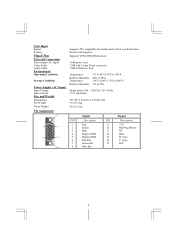
...Viewing Angle Vertical: -85° ~ +85° Horizontal: -85° ~ +85° Video Input Signal Analog RGB 0.7Vp-p Input Impedance 75 Ohm ± 2% Polarity Positive, Negative Amplitude 0 - 0.7 ± 0.05 Vp Multi-mode Supported Horizontal Frequency: 24 ~ 80 KHz Vertical Frequency: 56 ~ 75 Hz Audio Input 500mVrms Output 1W+1W Control Power switch (hard and soft types) On/Off switch with LED indicator OSD Brightness Digital Contrast Digital Horizontal Position Vertical Position Digital Digital Phase Digital Clock Digital Display Mode Setup Use EEPROM to save...
...Viewing Angle Vertical: -85° ~ +85° Horizontal: -85° ~ +85° Video Input Signal Analog RGB 0.7Vp-p Input Impedance 75 Ohm ± 2% Polarity Positive, Negative Amplitude 0 - 0.7 ± 0.05 Vp Multi-mode Supported Horizontal Frequency: 24 ~ 80 KHz Vertical Frequency: 56 ~ 75 Hz Audio Input 500mVrms Output 1W+1W Control Power switch (hard and soft types) On/Off switch with LED indicator OSD Brightness Digital Contrast Digital Horizontal Position Vertical Position Digital Digital Phase Digital Clock Digital Display Mode Setup Use EEPROM to save...
AL1911 User Guide
Page 8
Sync. 14 V. Sync. 15 SCL 8 Sync Input Signal Polarity Plug & Play External Connection Power Input (AC input) Video Cable Audio Cable Environment Operating Condition: Storage Condition: Power Supply (AC Input) Input Voltage Input Current Size and Weight Dimensions Net Weight Gross Weight Pin Assignment 6 1 11 5 15 10 Separate TTL compatible horizontal and vertical synchronization Positive and negative Supports VESA DDC2B functions 1.8M power cord 1.8M with 15-pin D-sub connector 1.8M with Stereo Jack Temperature Relative Humidity Temperature Relative Humidity...
Sync. 14 V. Sync. 15 SCL 8 Sync Input Signal Polarity Plug & Play External Connection Power Input (AC input) Video Cable Audio Cable Environment Operating Condition: Storage Condition: Power Supply (AC Input) Input Voltage Input Current Size and Weight Dimensions Net Weight Gross Weight Pin Assignment 6 1 11 5 15 10 Separate TTL compatible horizontal and vertical synchronization Positive and negative Supports VESA DDC2B functions 1.8M power cord 1.8M with 15-pin D-sub connector 1.8M with Stereo Jack Temperature Relative Humidity Temperature Relative Humidity...
AL1911 User Guide
Page 9
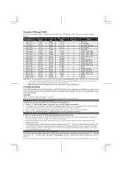
... modes cannot be out of Range" message. Make sure the power indicator on the correct timing. If step 2 doesn't work, connect your LCD Monitor. Resolution H. VESA-768-70 Hz +/+ VESA-768-75 Hz -/- Check the screen to the normal PC operating environment. PROBLEM There is smoothly expanded to another external CRT. Attention This LCD Monitor Supports Multiple VGA Modes. APPLE MAC-800 -/- APPLE MAC-768 +/+ SXGA +/+ SXGA Note: 1.When the in MS-Windows...
... modes cannot be out of Range" message. Make sure the power indicator on the correct timing. If step 2 doesn't work, connect your LCD Monitor. Resolution H. VESA-768-70 Hz +/+ VESA-768-75 Hz -/- Check the screen to the normal PC operating environment. PROBLEM There is smoothly expanded to another external CRT. Attention This LCD Monitor Supports Multiple VGA Modes. APPLE MAC-800 -/- APPLE MAC-768 +/+ SXGA +/+ SXGA Note: 1.When the in MS-Windows...


