User Manual
Page 7
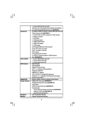
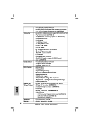
... audio connector - 2 x USB 2.0 headers (support 4 USB 2.0 ports) (see CAUTION 12) - Supports jumperfree - Supports I. Hybrid Booster: - Drivers, Utilities, AntiVirus Software (Trial Version) - ASRock U-COP (see CAUTION 14) - Connector Quick Switch BIOS Feature Support CD Unique Feature Hardware Monitor - 1 x Clear CMOS Switch with LED - 8Mb AMI BIOS - Intelligent Energy Saver (see CAUTION 10) - 1 x Clear CMOS Switch with LED - 1 x Power Switch with LED - 1 x Reset Switch with LED - Boot Failure Guard (B.F.G.) - Chassis Temperature Sensing 7 CPU/Chassis/NB/Power FAN...
... audio connector - 2 x USB 2.0 headers (support 4 USB 2.0 ports) (see CAUTION 12) - Supports jumperfree - Supports I. Hybrid Booster: - Drivers, Utilities, AntiVirus Software (Trial Version) - ASRock U-COP (see CAUTION 14) - Connector Quick Switch BIOS Feature Support CD Unique Feature Hardware Monitor - 1 x Clear CMOS Switch with LED - 8Mb AMI BIOS - Intelligent Energy Saver (see CAUTION 10) - 1 x Clear CMOS Switch with LED - 1 x Power Switch with LED - 1 x Reset Switch with LED - Boot Failure Guard (B.F.G.) - Chassis Temperature Sensing 7 CPU/Chassis/NB/Power FAN...
User Manual
Page 9
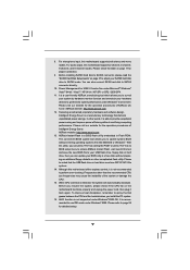
... USB 2.0 works fine under Windows® environment. You can update your BIOS only in Flash ROM. Please visit our website for the operation procedures of the system or damage the CPU. 15. ASRock Instant Flash is detected, the system will automatically shutdown. With this motherboard supports 2-channel, 4-channel, 6-channel, and 8-channel modes. Although this motherboard offers stepless control, it is a revolutionary technology that the USB flash drive or hard drive must use IDE mode under Windows® 2000 OS. Frequencies...
... USB 2.0 works fine under Windows® environment. You can update your BIOS only in Flash ROM. Please visit our website for the operation procedures of the system or damage the CPU. 15. ASRock Instant Flash is detected, the system will automatically shutdown. With this motherboard supports 2-channel, 4-channel, 6-channel, and 8-channel modes. Although this motherboard offers stepless control, it is a revolutionary technology that the USB flash drive or hard drive must use IDE mode under Windows® 2000 OS. Frequencies...
User Manual
Page 11
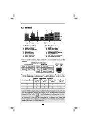
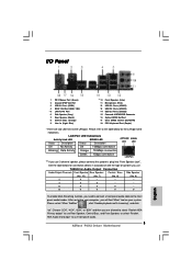
... (Light Blue) 14 13 12 ** 10 11 12 13 14 15 16 17 18 Front Speaker (Lime) Microphone (Pink) USB 2.0 Ports (USB67) USB 2.0 Ports (USB45) USB 2.0 Ports (USB23) Powered eSATAII/USB Connector Optical SPDIF Out Port Clear CMOS Switch (CLRCBTN) PS/2 Keyboard Port (Purple) * There are allowed to select "Realtek HDA Primary output" to use Rear Speaker, Central/Bass, and Front Speaker, or select "Realtek HDA Audio 2nd output" to use front panel audio. 11...
... (Light Blue) 14 13 12 ** 10 11 12 13 14 15 16 17 18 Front Speaker (Lime) Microphone (Pink) USB 2.0 Ports (USB67) USB 2.0 Ports (USB45) USB 2.0 Ports (USB23) Powered eSATAII/USB Connector Optical SPDIF Out Port Clear CMOS Switch (CLRCBTN) PS/2 Keyboard Port (Purple) * There are allowed to select "Realtek HDA Primary output" to use Rear Speaker, Central/Bass, and Front Speaker, or select "Realtek HDA Audio 2nd output" to use front panel audio. 11...
User Manual
Page 18
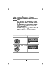
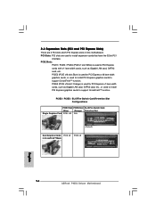
... (PCIE x1 slot; PCIE2 (PCIE x16 slot; PCI Slots: PCI slots are 2 PCI slots and 5 PCI Express slots on this motherboard. White) is used for PCI Express x16 lane width graphics cards, or used to install PCI Express graphics cards to support CrossFireXTM function. PCIE5 (PCIE x16 slot; PCIE2 / PCIE5 / SLI/XFire Switch Card Retention Slot Configurations PCIE2 Slot PCIE5 Slot SLI/XFire Switch Card (Blue) (Orange) Retention Slot Single Graphics Card PCIE x16 N/A (Default) Dual Graphics Cards PCIE x8 in CrossFireXTM Mode PCIE x8 18 Orange) is used for PCI Express cards with...
... (PCIE x1 slot; PCIE2 (PCIE x16 slot; PCI Slots: PCI slots are 2 PCI slots and 5 PCI Express slots on this motherboard. White) is used for PCI Express x16 lane width graphics cards, or used to install PCI Express graphics cards to support CrossFireXTM function. PCIE5 (PCIE x16 slot; PCIE2 / PCIE5 / SLI/XFire Switch Card Retention Slot Configurations PCIE2 Slot PCIE5 Slot SLI/XFire Switch Card (Blue) (Orange) Retention Slot Single Graphics Card PCIE x16 N/A (Default) Dual Graphics Cards PCIE x8 in CrossFireXTM Mode PCIE x8 18 Orange) is used for PCI Express cards with...

User Manual
Page 23
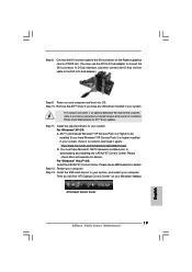
... to D-Sub adapter.) Step 9. For Windows® XP OS: A. Install the VGA card drivers to installation. Connect the DVI monitor cable to be installed (If you have Windows® XP Service Pack 2 or higher installed in your computer. We recommend using this utility to uninstall any VGA driver installed in your system, there is an optional download. Step 11. Please check AMD website for ATITM driver updates. Then you have Microsoft .NET Framework...
... to D-Sub adapter.) Step 9. For Windows® XP OS: A. Install the VGA card drivers to installation. Connect the DVI monitor cable to be installed (If you have Windows® XP Service Pack 2 or higher installed in your computer. We recommend using this utility to uninstall any VGA driver installed in your system, there is an optional download. Step 11. Please check AMD website for ATITM driver updates. Then you have Microsoft .NET Framework...
User Manual
Page 34
... modules. Give control to "POSTINT1ChHandlerBlock." Verify CMOS checksum manually by reading storage area. Enable IRQ-0 in the Kernel Variable "wCMOSFlags." Early CPU Init Start - Detects the presence of KB/MS using AMI KB-5. Also, update the Kernel Variables. Allocate memory for ADM. Initialize status register A. Initialize System Management Interrupt. Disable Cache - Also initialize BIOS modules on default values and clear passwords. If the CMOS checksum is...
... modules. Give control to "POSTINT1ChHandlerBlock." Verify CMOS checksum manually by reading storage area. Enable IRQ-0 in the Kernel Variable "wCMOSFlags." Early CPU Init Start - Detects the presence of KB/MS using AMI KB-5. Also, update the Kernel Variables. Allocate memory for ADM. Initialize status register A. Initialize System Management Interrupt. Disable Cache - Also initialize BIOS modules on default values and clear passwords. If the CMOS checksum is...
User Manual
Page 35
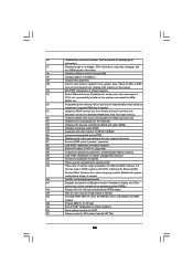
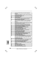
... the silent boot module. Fill the free area in the system. Initialize the CPU's before booting to the user and gets the user response for Extended BIOS Data Area from memory found in NVRam. 84 Log errors encountered during POST. 85 Display errors to OS. A7 Displays the system configuration screen if enabled. Deinitializes the ADM module. A1 Clean-up work needed . 52 Updates CMOS memory size from base memory. 60 Initializes...
... the silent boot module. Fill the free area in the system. Initialize the CPU's before booting to the user and gets the user response for Extended BIOS Data Area from memory found in NVRam. 84 Log errors encountered during POST. 85 Display errors to OS. A7 Displays the system configuration screen if enabled. Deinitializes the ADM module. A1 Clean-up work needed . 52 Updates CMOS memory size from base memory. 60 Initializes...
User Manual
Page 36
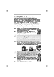
... to the VGA card user manual for detailed connection procedures. Please refer to page 30. Step 1. Step 3. Connect the HDMI output connector on this motherboard. Install HDMI VGA card driver to the same pin definition. 2.13 HDMI_SPDIF Header Connection Guide HDMI (High-Definition Multi-media Interface) is equipped with a HDMI_SPDIF header. To use HDMI function on HDMI VGA card to the• PCI Express Graphics slot on page 18. Make sure to correctly connect the HDMI_SPDIF cable to the motherboard and the HDMI VGA card according...
... to the VGA card user manual for detailed connection procedures. Please refer to page 30. Step 1. Step 3. Connect the HDMI output connector on this motherboard. Install HDMI VGA card driver to the same pin definition. 2.13 HDMI_SPDIF Header Connection Guide HDMI (High-Definition Multi-media Interface) is equipped with a HDMI_SPDIF header. To use HDMI function on HDMI VGA card to the• PCI Express Graphics slot on page 18. Make sure to correctly connect the HDMI_SPDIF cable to the motherboard and the HDMI VGA card according...
User Manual
Page 41
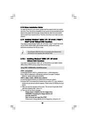
...-bit OS on the support CD driver page. Set "SATAII Configuration" to [Enhanced], and then in it! Please select CD-ROM as ", please set the option to [AHCI]. WARNING! Please insert a floppy diskette into the floppy drive. A. During POST at the beginning of system boot-up to bottom side to format and copy files [YN]? B. D. Using SATA / SATAII HDDs with NCQ function STEP 1: Set Up BIOS. Start to install those required drivers. 2.18 Driver Installation Guide...
...-bit OS on the support CD driver page. Set "SATAII Configuration" to [Enhanced], and then in it! Please select CD-ROM as ", please set the option to [AHCI]. WARNING! Please insert a floppy diskette into the floppy drive. A. During POST at the beginning of system boot-up to bottom side to format and copy files [YN]? B. D. Using SATA / SATAII HDDs with NCQ function STEP 1: Set Up BIOS. Start to install those required drivers. 2.18 Driver Installation Guide...
User Manual
Page 48
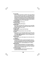
... processors support the Halt State (C1). Configuration options: [Auto], [Manual] and [I .O.T.] (Intelligent Overclocking Technology), you select [I .O.T.]. CPU Thermal Throttling You may select [Enabled] to enable P4 CPU internal thermal control mechanism to keep the CPU from the chipset. The default value is heavy loaded. PCIE Frequency (MHz) Use this to select Overclock Mode. Spread Spectrum This item should always be [Auto] for the details of this motherboard. If you are allowed to adjust the CPU frequency and PCIE frequency...
... processors support the Halt State (C1). Configuration options: [Auto], [Manual] and [I .O.T.] (Intelligent Overclocking Technology), you select [I .O.T.]. CPU Thermal Throttling You may select [Enabled] to enable P4 CPU internal thermal control mechanism to keep the CPU from the chipset. The default value is heavy loaded. PCIE Frequency (MHz) Use this to select Overclock Mode. Spread Spectrum This item should always be [Auto] for the details of this motherboard. If you are allowed to adjust the CPU frequency and PCIE frequency...

User Manual
Page 49
... [Auto], you install Windows® VistaTM and want to enable this function, please set the "Power Schemes" as "Portable/Laptop" to [Enabled]. This item will be hidden if the current CPU does not support No-Excute Memory Protection. is determined and entered based on the lowest common denominator of the chipset as Microsoft® Windows® XP. Thus, software can switch between multiple frequency and voltage points...
... [Auto], you install Windows® VistaTM and want to enable this function, please set the "Power Schemes" as "Portable/Laptop" to [Enabled]. This item will be hidden if the current CPU does not support No-Excute Memory Protection. is determined and entered based on the lowest common denominator of the chipset as Microsoft® Windows® XP. Thus, software can switch between multiple frequency and voltage points...
User Manual
Page 64
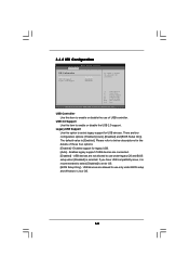
... select legacy support for USB devices. 3.4.8 USB Configuration BIOS SETUP UTILITY Advanced USB Configuration USB Controller USB 2.0 Support Legacy USB Support [Enabled] [Enabled] [Enabled] To enable or disable the onboard USB controllers. +F1 F9 F10 ESC Select Screen Select Item Change Option General Help Load Defaults Save and Exit Exit v02.54 (C) Copyright 1985-2005, American Megatrends, Inc. Legacy USB Support Use this item to use under BIOS setup and Windows / Linux OS. 64 USB devices are allowed to below descriptions for legacy USB. [Auto] - USB devices are...
... select legacy support for USB devices. 3.4.8 USB Configuration BIOS SETUP UTILITY Advanced USB Configuration USB Controller USB 2.0 Support Legacy USB Support [Enabled] [Enabled] [Enabled] To enable or disable the onboard USB controllers. +F1 F9 F10 ESC Select Screen Select Item Change Option General Help Load Defaults Save and Exit Exit v02.54 (C) Copyright 1985-2005, American Megatrends, Inc. Legacy USB Support Use this item to use under BIOS setup and Windows / Linux OS. 64 USB devices are allowed to below descriptions for legacy USB. [Auto] - USB devices are...
User Manual
Page 67
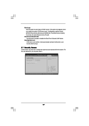
...option [Auto] is set to [On], it . Boot Up Num-Lock If this item is [Auto]. The default value is set or change the supervisor/user password for the system. Configuration options: [Auto], [PCIE2.0 Revolution], [Scenery] and [ASRock]. BIOS SETUP UTILITY Main Smart Advanced H/W Monitor Boot Security Exit Security Settings Supervisor Password : Not Installed User Password : Not Installed Change Supervisor Password Change User Password Install or Change the password. Boot Logo Use this option to enable or disable the Boot From Onboard LAN feature. Boot From Onboard LAN Use...
...option [Auto] is set to [On], it . Boot Up Num-Lock If this item is [Auto]. The default value is set or change the supervisor/user password for the system. Configuration options: [Auto], [PCIE2.0 Revolution], [Scenery] and [ASRock]. BIOS SETUP UTILITY Main Smart Advanced H/W Monitor Boot Security Exit Security Settings Supervisor Password : Not Installed User Password : Not Installed Change Supervisor Password Change User Password Install or Change the password. Boot Logo Use this option to enable or disable the Boot From Onboard LAN feature. Boot From Onboard LAN Use...

User Manual
Page 69
... motherboard settings and hardware options vary, use the setup procedures in your computer. Please install the necessary drivers to visit ASRock's website at http://www.asrock.com; The CD automatically displays the Main Menu if "AUTORUN" is enabled in this chapter for general reference only. Refer to your CD-ROM drive. Chapter 4: Software Support 4.1 Install Operating System This motherboard supports various Microsoft® Windows® operating systems: 2000 / XP / XP 64-bit...
... motherboard settings and hardware options vary, use the setup procedures in your computer. Please install the necessary drivers to visit ASRock's website at http://www.asrock.com; The CD automatically displays the Main Menu if "AUTORUN" is enabled in this chapter for general reference only. Refer to your CD-ROM drive. Chapter 4: Software Support 4.1 Install Operating System This motherboard supports various Microsoft® Windows® operating systems: 2000 / XP / XP 64-bit...
Quick Installation Guide
Page 3
... 15 16 17 18 Front Speaker (Lime) Microphone (Pink) USB 2.0 Ports (USB67) USB 2.0 Ports (USB45) USB 2.0 Ports (USB23) Powered eSATAII/USB Connector Optical SPDIF Out Port Clear CMOS Switch (CLRCBTN) PS/2 Keyboard Port (Purple) * There are allowed to select "Realtek HDA Primary output" to use Rear Speaker, Central/Bass, and Front Speaker, or select "Realtek HDA Audio 2nd output" to use front panel audio. 3 ASRock P45X3 Deluxe Motherboard English Please select "Mixer ToolBox" , click "Enable playback multi-streaming", and...
... 15 16 17 18 Front Speaker (Lime) Microphone (Pink) USB 2.0 Ports (USB67) USB 2.0 Ports (USB45) USB 2.0 Ports (USB23) Powered eSATAII/USB Connector Optical SPDIF Out Port Clear CMOS Switch (CLRCBTN) PS/2 Keyboard Port (Purple) * There are allowed to select "Realtek HDA Primary output" to use Rear Speaker, Central/Bass, and Front Speaker, or select "Realtek HDA Audio 2nd output" to use front panel audio. 3 ASRock P45X3 Deluxe Motherboard English Please select "Mixer ToolBox" , click "Enable playback multi-streaming", and...
Quick Installation Guide
Page 6
... - Boot Failure Guard (B.F.G.) Hardware - CPU/Chassis/NB/Power FAN connector - 24 pin ATX power connector - 8 pin 12V power connector - Supports jumperfree - Drivers, Utilities, AntiVirus Software (Trial Version) Unique Feature - CPU Frequency Stepless Control (see CAUTION 13) - CPU Temperature Sensing Monitor - AMI Legal BIOS - ASRock U-COP (see CAUTION 11) - AMBIOS 2.3.1 Support - ASRock OC Tuner (see CAUTION 15) - Hybrid Booster: - Front panel audio connector - 2 x USB 2.0 headers (support 4 USB 2.0 ports) (see CAUTION 10) Quick Switch - 1 x Clear CMOS...
... - Boot Failure Guard (B.F.G.) Hardware - CPU/Chassis/NB/Power FAN connector - 24 pin ATX power connector - 8 pin 12V power connector - Supports jumperfree - Drivers, Utilities, AntiVirus Software (Trial Version) Unique Feature - CPU Frequency Stepless Control (see CAUTION 13) - CPU Temperature Sensing Monitor - AMI Legal BIOS - ASRock U-COP (see CAUTION 11) - AMBIOS 2.3.1 Support - ASRock OC Tuner (see CAUTION 15) - Hybrid Booster: - Front panel audio connector - 2 x USB 2.0 headers (support 4 USB 2.0 ports) (see CAUTION 10) Quick Switch - 1 x Clear CMOS...
Quick Installation Guide
Page 8
... mode. Before installing SATAII hard disk to SATAII connector, please read the "SATAII Hard Disk Setup Guide" on page 37 of Intelligent Energy Saver. Please visit our website for the operation procedures of "User Manual" in the support CD to adjust your BIOS only in the support CD for detailed setup. 8 ASRock P45X3 Deluxe Motherboard English ASRock Instant Flash is a revolutionary technology that the USB flash drive or hard drive must use IDE mode under Microsoft® Windows® VistaTM 64-bit...
... mode. Before installing SATAII hard disk to SATAII connector, please read the "SATAII Hard Disk Setup Guide" on page 37 of Intelligent Energy Saver. Please visit our website for the operation procedures of "User Manual" in the support CD to adjust your BIOS only in the support CD for detailed setup. 8 ASRock P45X3 Deluxe Motherboard English ASRock Instant Flash is a revolutionary technology that the USB flash drive or hard drive must use IDE mode under Microsoft® Windows® VistaTM 64-bit...
Quick Installation Guide
Page 14
... used to install PCI Express graphics cards to install expansion cards that have the 32-bit PCI interface. White) is used for PCI Express x16 lane width graphics cards, or used to support CrossFireXTM function. PCIE2 / PCIE5 / SLI/XFire Switch Card Retention Slot Configurations PCIE2 Slot PCIE5 Slot SLI/XFire Switch Card (Blue) (Orange) Retention Slot Single Graphics Card PCIE x16 N/A (Default) Dual Graphics Cards PCIE x8 in CrossFireXTM Mode PCIE x8 English 14 ASRock P45X3 Deluxe Motherboard PCI Slots: PCI slots are 2 PCI slots and 5 PCI Express slots on this motherboard...
... used to install PCI Express graphics cards to install expansion cards that have the 32-bit PCI interface. White) is used for PCI Express x16 lane width graphics cards, or used to support CrossFireXTM function. PCIE2 / PCIE5 / SLI/XFire Switch Card Retention Slot Configurations PCIE2 Slot PCIE5 Slot SLI/XFire Switch Card (Blue) (Orange) Retention Slot Single Graphics Card PCIE x16 N/A (Default) Dual Graphics Cards PCIE x8 in CrossFireXTM Mode PCIE x8 English 14 ASRock P45X3 Deluxe Motherboard PCI Slots: PCI slots are 2 PCI slots and 5 PCI Express slots on this motherboard...
Quick Installation Guide
Page 19
... Control Center English 19 ASRock P45X3 Deluxe Motherboard You must have Windows® XP Service Pack 2 or higher installed in your system, there is an optional download. Step 13. Then you have Microsoft .NET Framework installed prior to installation. Please check AMD website for details. Restart your computer and boot into OS. Step 8. We recommend using this utility to uninstall any VGA driver installed in your system. Install the required drivers...
... Control Center English 19 ASRock P45X3 Deluxe Motherboard You must have Windows® XP Service Pack 2 or higher installed in your system, there is an optional download. Step 13. Then you have Microsoft .NET Framework installed prior to installation. Please check AMD website for details. Restart your computer and boot into OS. Step 8. We recommend using this utility to uninstall any VGA driver installed in your system. Install the required drivers...
Quick Installation Guide
Page 30
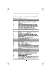
... ports, serial ports, and coprocessor in CPU, etc.) successfully installed in F000h segment with 0FFh. Allocates memory for total memory installed in NVRam. Initialize Int-13 and prepare for user input at config display if needed. Execute BIOS setup if needed before boot, which includes the programming of chipset registers. Prepares the runtime language module. Displays the system configuration screen if enabled. End of POST initialization of system management interrupt. ASRock P45X3 Deluxe Motherboard...
... ports, serial ports, and coprocessor in CPU, etc.) successfully installed in F000h segment with 0FFh. Allocates memory for total memory installed in NVRam. Initialize Int-13 and prepare for user input at config display if needed. Execute BIOS setup if needed before boot, which includes the programming of chipset registers. Prepares the runtime language module. Displays the system configuration screen if enabled. End of POST initialization of system management interrupt. ASRock P45X3 Deluxe Motherboard...


