User Manual
Page 4
... 44 3.1 Introduction 44 3.1.1 BIOS Menu Bar 44 3.1.2 Navigation Keys 45 3.2 Main Screen 45 3.3 Smart Screen 46 3.4 Advanced Screen 46 3.4.1 CPU Configuration 47 3.4.2 Chipset Configuration 50 3.4.3 ACPI Configuration 58 3.4.4 IDE ...
... 44 3.1 Introduction 44 3.1.1 BIOS Menu Bar 44 3.1.2 Navigation Keys 45 3.2 Main Screen 45 3.3 Smart Screen 46 3.4 Advanced Screen 46 3.4.1 CPU Configuration 47 3.4.2 Chipset Configuration 50 3.4.3 ACPI Configuration 58 3.4.4 IDE ...
User Manual
Page 5
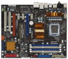
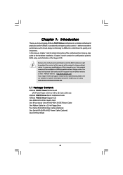
... to quality and endurance. It delivers excellent performance with robust design conforming to ASRock's commitment to BIOS setup and information of the motherboard and step-by-step guide to the hardware installation. www.asrock.com/support/index.asp 1.1 Package Contents ASRock P45X3 Deluxe Motherboard (ATX Form Factor: 12.0-in x 9.6-in Floppy Drive Four Serial ATA (SATA...
... to quality and endurance. It delivers excellent performance with robust design conforming to ASRock's commitment to BIOS setup and information of the motherboard and step-by-step guide to the hardware installation. www.asrock.com/support/index.asp 1.1 Package Contents ASRock P45X3 Deluxe Motherboard (ATX Form Factor: 12.0-in x 9.6-in Floppy Drive Four Serial ATA (SATA...
User Manual
Page 7
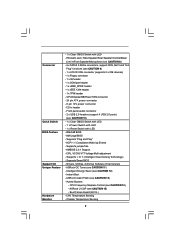
..., AntiVirus Software (Trial Version) - Instant Boot - CPU Temperature Sensing - Chassis Temperature Sensing 7 T. (Intelligent Overclocking Technology) - Connector Quick Switch BIOS Feature Support CD Unique Feature Hardware Monitor - 1 x Clear CMOS Switch with LED - 8Mb AMI BIOS - ASRock U-COP (see CAUTION 13) - CD in /Front Speaker/Microphone (see CAUTION 8) - 6 x SATAII 3.0Gb/s connectors, support NCQ, AHCI and...
..., AntiVirus Software (Trial Version) - Instant Boot - CPU Temperature Sensing - Chassis Temperature Sensing 7 T. (Intelligent Overclocking Technology) - Connector Quick Switch BIOS Feature Support CD Unique Feature Hardware Monitor - 1 x Clear CMOS Switch with LED - 8Mb AMI BIOS - ASRock U-COP (see CAUTION 13) - CD in /Front Speaker/Microphone (see CAUTION 8) - 6 x SATAII 3.0Gb/s connectors, support NCQ, AHCI and...
User Manual
Page 8
FCC, CE, WHQL * For detailed product information, please visit our website: http://www.asrock.com WARNING Please realize that there is no such limitation. 7. Please read the installation guide of your own risk and expense. Please ..."Untied Overclocking Technology" on page 21 to reverse the direction of "Hyper Threading Technology", please check page 49. 3. About the setting of ASRock SLI/XFire Switch Card in the BIOS, applying Untied Overclocking Technology, or using the thirdparty overclocking tools. Voltage Monitoring: +12V, +5V, +3.3V, CPU Vcore OS - Overclocking ...
FCC, CE, WHQL * For detailed product information, please visit our website: http://www.asrock.com WARNING Please realize that there is no such limitation. 7. Please read the installation guide of your own risk and expense. Please ..."Untied Overclocking Technology" on page 21 to reverse the direction of "Hyper Threading Technology", please check page 49. 3. About the setting of ASRock SLI/XFire Switch Card in the BIOS, applying Untied Overclocking Technology, or using the thirdparty overclocking tools. Voltage Monitoring: +12V, +5V, +3.3V, CPU Vcore OS - Overclocking ...
User Manual
Page 9
... Guide" on page 37 to adjust your BIOS only in Flash ROM. Please visit our website for the operation procedures of Intelligent Energy Saver. In other words, it is able to access ASRock Instant Flash. This convenient BIOS update tool allows you install the PC system.... 16. Although this motherboard offers stepless control, it is not recommended to update system BIOS without sacrificing computing performance. For microphone input, this motherboard...
... Guide" on page 37 to adjust your BIOS only in Flash ROM. Please visit our website for the operation procedures of Intelligent Energy Saver. In other words, it is able to access ASRock Instant Flash. This convenient BIOS update tool allows you install the PC system.... 16. Although this motherboard offers stepless control, it is not recommended to update system BIOS without sacrificing computing performance. For microphone input, this motherboard...
User Manual
Page 10
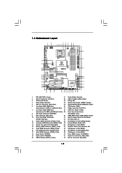
... Center: Bottom: PWR_FAN1 LAN PHY 1 CLRCMOS1 PCIE1 CMOS Battery Intel P45 Chipset Super I/O PCIE2 PCIE3 P45X3 Deluxe FSB2000 IDE1 VIA VT6330 FRONT_1394 1 IR1 1 AUDIO CODEC CD1 PCIE4 CrossFireX PCI Express 2.0 PCIE5 1394a PCI1 RoHS Debug LED 8Mb BIOS 1 HDMI_SPDIF1 1 HD_AUDIO1 COM1 PCI2 FLOPPY1 1 1 TPM1 SPEAKER1 1 PANEL1 PLED PWRBTN 1 HDLED RESET CHA_FAN1 Intel ICH10...
... Center: Bottom: PWR_FAN1 LAN PHY 1 CLRCMOS1 PCIE1 CMOS Battery Intel P45 Chipset Super I/O PCIE2 PCIE3 P45X3 Deluxe FSB2000 IDE1 VIA VT6330 FRONT_1394 1 IR1 1 AUDIO CODEC CD1 PCIE4 CrossFireX PCI Express 2.0 PCIE5 1394a PCI1 RoHS Debug LED 8Mb BIOS 1 HDMI_SPDIF1 1 HD_AUDIO1 COM1 PCI2 FLOPPY1 1 1 TPM1 SPEAKER1 1 PANEL1 PLED PWRBTN 1 HDLED RESET CHA_FAN1 Intel ICH10...
User Manual
Page 25
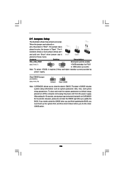
... the jumper cap is "Short". The il- Note: To select +5VSB, it down before you do not clear the CMOS right after you update the BIOS. After waiting for 15 seconds, use a jumper cap to enable +5VSB (standby) for 5 seconds. If no jumper cap is "Open". To clear and reset the... setup information such as system password, date, time, and system setup parameters. If you need to clear the CMOS when you just finish updating the BIOS, you to default setup, please turn off the computer and unplug the power cord from the power supply. Jumper Setting Description PS2_USB_PWR1 (see p.10 No...
... the jumper cap is "Short". The il- Note: To select +5VSB, it down before you do not clear the CMOS right after you update the BIOS. After waiting for 15 seconds, use a jumper cap to enable +5VSB (standby) for 5 seconds. If no jumper cap is "Open". To clear and reset the... setup information such as system password, date, time, and system setup parameters. If you need to clear the CMOS when you just finish updating the BIOS, you to default setup, please turn off the computer and unplug the power cord from the power supply. Jumper Setting Description PS2_USB_PWR1 (see p.10 No...
User Manual
Page 28
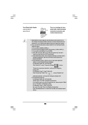
...; 2000 / XP / XP 64-bit OS: Click "Audio I/O", select "Connector Settings" , choose "Disable front panel jack detection", and save the change by clicking "OK". D. Enter BIOS Setup Utility. Enter Windows system. Set the Front Panel Control option from [Auto] to Ground (GND). Click the icon on the chassis must support HDA...
...; 2000 / XP / XP 64-bit OS: Click "Audio I/O", select "Connector Settings" , choose "Disable front panel jack detection", and save the change by clicking "OK". D. Enter BIOS Setup Utility. Enter Windows system. Set the Front Panel Control option from [Auto] to Ground (GND). Click the icon on the chassis must support HDA...
User Manual
Page 33
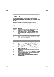
... before memory detection. Verify the bootblock checksum. Verify that flat mode is available. Test base 512KB memory. Set stack. BIOS now executes out of the BIOS: Checkpoint Before D1 D1 D0 D2 D3 D4 D5 D6 D7 D8 D9 DA Description Early chipset initialization is stored in PMM...and OEM specific method is checked to it . Give control to checkpoint E0. Early super I/O initialization is forced. If BIOS recovery is given to determine if BIOS recovery is done including RTC and keyboard controller. The Bootblock-Runtime interface module is moved to system memory and control is ...
... before memory detection. Verify the bootblock checksum. Verify that flat mode is available. Test base 512KB memory. Set stack. BIOS now executes out of the BIOS: Checkpoint Before D1 D1 D0 D2 D3 D4 D5 D6 D7 D8 D9 DA Description Early chipset initialization is stored in PMM...and OEM specific method is checked to it . Give control to checkpoint E0. Early super I/O initialization is forced. If BIOS recovery is given to determine if BIOS recovery is done including RTC and keyboard controller. The Bootblock-Runtime interface module is moved to system memory and control is ...
User Manual
Page 34
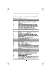
...interrupt vector table. Check CMOS diagnostic byte to "POSTINT1ChHandlerBlock." Initializes data variables that have optional ROMs. Initializes all available language, BIOS logo, and Silent logo modules. Traps INT1Ch vector to determine if battery power is OK and CMOS checksum is bad, ... of chipset registers. Initialized CMOS as system timer. If the CMOS checksum is OK. Uncompress and initialize any platform specific BIOS modules. Initialize language and font modules for system timer interrupt. Early POST initialization of different Input Devices. Detects and initializes ...
...interrupt vector table. Check CMOS diagnostic byte to "POSTINT1ChHandlerBlock." Initializes data variables that have optional ROMs. Initializes all available language, BIOS logo, and Silent logo modules. Traps INT1Ch vector to determine if battery power is OK and CMOS checksum is bad, ... of chipset registers. Initialized CMOS as system timer. If the CMOS checksum is OK. Uncompress and initialize any platform specific BIOS modules. Initialize language and font modules for system timer interrupt. Early POST initialization of different Input Devices. Detects and initializes ...
User Manual
Page 35
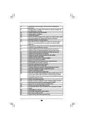
... Check boot password if installed. Initialize the CPU's before booting to the user and gets the user response for error. 87 Execute BIOS setup if needed before boot, which includes the programming of chipset registers. 40 Detect different devices (Parallel ports, serial ports, and ...A2 Takes care of system management interrupt. AB Prepare BBS for OS boot including final MTRR values. B1 Save system context for different BIOS modules. Prepares the runtime language module. AC End of POST initialization of chipset registers. 8D Build ACPI tables (if ACPI is supported...
... Check boot password if installed. Initialize the CPU's before booting to the user and gets the user response for error. 87 Execute BIOS setup if needed before boot, which includes the programming of chipset registers. 40 Detect different devices (Parallel ports, serial ports, and ...A2 Takes care of system management interrupt. AB Prepare BBS for OS boot including final MTRR values. B1 Save system context for different BIOS modules. Prepares the runtime language module. AC End of POST initialization of chipset registers. 8D Build ACPI tables (if ACPI is supported...
User Manual
Page 41
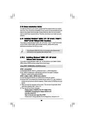
... drivers you install can be auto-detected and listed on your SATA / SATAII HDDs without RAID functions, please follow below steps. Enter BIOS SETUP UTILITY Advanced screen IDE Configuration. Please select CD-ROM as ", please set the option to [AHCI]. When you install. Formatting ... install the drivers to your system, please insert the support CD to your system. Using SATA / SATAII HDDs with NCQ function STEP 1: Set Up BIOS. B. WARNING! B. Please follow below procedures according to the OS you see these messages, Please insert a diskette into the floppy drive. STEP 2:...
... drivers you install can be auto-detected and listed on your SATA / SATAII HDDs without RAID functions, please follow below steps. Enter BIOS SETUP UTILITY Advanced screen IDE Configuration. Please select CD-ROM as ", please set the option to [AHCI]. When you install. Formatting ... install the drivers to your system, please insert the support CD to your system. Using SATA / SATAII HDDs with NCQ function STEP 1: Set Up BIOS. B. WARNING! B. Please follow below procedures according to the OS you see these messages, Please insert a diskette into the floppy drive. STEP 2:...
User Manual
Page 42
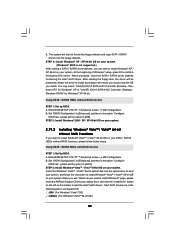
... and click the "Load Driver" button on the left on your system. You may select: "Intel(R) ICH10 SATA AHCI Controller (Desktop - Enter BIOS SETUP UTILITY Advanced screen IDE Configuration. STEP 2: Install Windows® VistaTM / VistaTM 64-bit OS on your system. 2.19.2 Installing Windows®...2: Install Windows® 2000 / XP / XP 64-bit OS on your SATA / SATAII HDDs without NCQ function STEP 1: Set up BIOS. page, please insert the ASRock Support CD into the floppy diskette. Set "SATAII Configuration" to [Enhanced], and then in the option "Configure SATAII as ", please set ...
... and click the "Load Driver" button on the left on your system. You may select: "Intel(R) ICH10 SATA AHCI Controller (Desktop - Enter BIOS SETUP UTILITY Advanced screen IDE Configuration. STEP 2: Install Windows® VistaTM / VistaTM 64-bit OS on your system. 2.19.2 Installing Windows®...2: Install Windows® 2000 / XP / XP 64-bit OS on your SATA / SATAII HDDs without NCQ function STEP 1: Set up BIOS. page, please insert the ASRock Support CD into the floppy diskette. Set "SATAII Configuration" to [Enhanced], and then in the option "Configure SATAII as ", please set ...
User Manual
Page 43
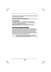
...that FSB can operate under a more stable overclocking environment. B. Before you enable Untied Overclocking function, please enter "Overclock Mode" option of BIOS setup to set the selection from [Auto] to the warning on your system. 2.20 Untied Overclocking Technology This motherboard supports Untied Overclocking ...[IDE]. Therefore, CPU FSB is untied during overclocking, FSB enjoys better margin due to continue the installation. Enter BIOS SETUP UTILITY Advanced screen IDE Configuration. Please refer to [Manual]. A. Using SATA / SATAII HDDs without NCQ function STEP 1: Set up...
...that FSB can operate under a more stable overclocking environment. B. Before you enable Untied Overclocking function, please enter "Overclock Mode" option of BIOS setup to set the selection from [Auto] to the warning on your system. 2.20 Untied Overclocking Technology This motherboard supports Untied Overclocking ...[IDE]. Therefore, CPU FSB is untied during overclocking, FSB enjoys better margin due to continue the installation. Enter BIOS SETUP UTILITY Advanced screen IDE Configuration. Please refer to [Manual]. A. Using SATA / SATAII HDDs without NCQ function STEP 1: Set up...
User Manual
Page 44
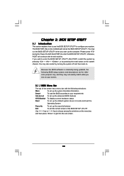
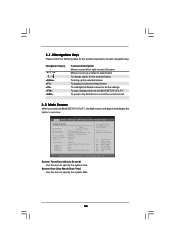
... reference purpose only, and they may not exactly match what you see on your screen. 3.1.1 BIOS Menu Bar The top of the screen has a menu bar with its test routines. You may... also restart by pressing the reset button on the menu bar, and then press to enter the BIOS SETUP UTILITY, otherwise, POST will continue with the following selections: Main To set up the system time/date ...-On-Self-Test (POST) to get into the sub screen. 44 You may run the BIOS SETUP UTILITY when you wish to enter the BIOS SETUP UTILITY after POST, restart the system by pressing + + , or by turning the ...
... reference purpose only, and they may not exactly match what you see on your screen. 3.1.1 BIOS Menu Bar The top of the screen has a menu bar with its test routines. You may... also restart by pressing the reset button on the menu bar, and then press to enter the BIOS SETUP UTILITY, otherwise, POST will continue with the following selections: Main To set up the system time/date ...-On-Self-Test (POST) to get into the sub screen. 44 You may run the BIOS SETUP UTILITY when you wish to enter the BIOS SETUP UTILITY after POST, restart the system by pressing + + , or by turning the ...
User Manual
Page 45
...Smart Advanced H/W Monitor Boot Security Exit System Overview System Time System Date [14:00:09] [Thu 05/21/2009] BIOS Version : P45X3 Deluxe P1.00 Processor Type : Intel (R) Core (TM) 2 Duo CPU E7500 @ 2.936GHz (64bit) Processor Speed : ... following table for all the settings To save changes and exit the BIOS SETUP UTILITY To jump to the Exit Screen or exit the current screen 3.2 Main Screen When you enter ...the BIOS SETUP UTILITY, the Main screen will appear and display the system overview. System Time [Hour...
...Smart Advanced H/W Monitor Boot Security Exit System Overview System Time System Date [14:00:09] [Thu 05/21/2009] BIOS Version : P45X3 Deluxe P1.00 Processor Type : Intel (R) Core (TM) 2 Duo CPU E7500 @ 2.936GHz (64bit) Processor Speed : ... following table for all the settings To save changes and exit the BIOS SETUP UTILITY To jump to the Exit Screen or exit the current screen 3.2 Main Screen When you enter ...the BIOS SETUP UTILITY, the Main screen will appear and display the system overview. System Time [Hour...
User Manual
Page 46
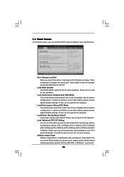
...Optimized CPU OC Setting You can be compatible with all system configurations. ASRock Instant Flash ASRock Instant Flash is a BIOS flash utility embedded in Flash ROM. Select Screen Select Item Enter Go to update system BIOS without entering operating systems first like MS-DOS or Windows®. Load...IDE/SATA) Load Performance Setup AHCI Mode Load Power Saving Setup Default EZ Overclocking Load Optimized CPU OC Setting [Press Enter] BIOS Update Utility ASRock Instant Flash Exit system setup after saving the changes. Just launch 46 F3 key can be used for all system configurations....
...Optimized CPU OC Setting You can be compatible with all system configurations. ASRock Instant Flash ASRock Instant Flash is a BIOS flash utility embedded in Flash ROM. Select Screen Select Item Enter Go to update system BIOS without entering operating systems first like MS-DOS or Windows®. Load...IDE/SATA) Load Performance Setup AHCI Mode Load Power Saving Setup Default EZ Overclocking Load Optimized CPU OC Setting [Press Enter] BIOS Update Utility ASRock Instant Flash Exit system setup after saving the changes. Just launch 46 F3 key can be used for all system configurations....

User Manual
Page 47
...and Exit Exit v02.54 (C) Copyright 1985-2005, American Megatrends, Inc. 47 If you execute ASRock Instant Flash utility, the utility will show the BIOS files and their respective information. BIOS SETUP UTILITY Main Smart Advanced H/W Monitor Boot Security Exit Advanced Settings WARNING : Setting wrong values in... F10 Save and Exit ESC Exit v02.54 (C) Copyright 1985-2005, American Megatrends, Inc. Select the proper BIOS file to update your BIOS, and reboot your BIOS only in a few clicks without preparing an additional floppy diskette or other complicated flash utility. this tool and ...
...and Exit Exit v02.54 (C) Copyright 1985-2005, American Megatrends, Inc. 47 If you execute ASRock Instant Flash utility, the utility will show the BIOS files and their respective information. BIOS SETUP UTILITY Main Smart Advanced H/W Monitor Boot Security Exit Advanced Settings WARNING : Setting wrong values in... F10 Save and Exit ESC Exit v02.54 (C) Copyright 1985-2005, American Megatrends, Inc. Select the proper BIOS file to update your BIOS, and reboot your BIOS only in a few clicks without preparing an additional floppy diskette or other complicated flash utility. this tool and ...
User Manual
Page 50
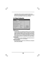
... The configuration options depend on the CPU and memory module you adopt on this option is [Disabled]. 3.4.2 Chipset Configuration BIOS SETUP UTILITY Advanced Chipset Settings DRAM Frequency Flexibility Option DRAM Command Rate [Auto] [Disabled] [Auto] DRAM Timing Configuration ...DRAM RCOMP and tRD Configuration DRAM DLL SKEW Configuration Voltage Configuration Intelligent Energy Saver ASRock VDrop Control Primary Graphics Adapter Onboard HD Audio Front Panel CD-In OnBoard Lan [Disabled] [With VDrop] [PCI] [Auto] [Enabled...
... The configuration options depend on the CPU and memory module you adopt on this option is [Disabled]. 3.4.2 Chipset Configuration BIOS SETUP UTILITY Advanced Chipset Settings DRAM Frequency Flexibility Option DRAM Command Rate [Auto] [Disabled] [Auto] DRAM Timing Configuration ...DRAM RCOMP and tRD Configuration DRAM DLL SKEW Configuration Voltage Configuration Intelligent Energy Saver ASRock VDrop Control Primary Graphics Adapter Onboard HD Audio Front Panel CD-In OnBoard Lan [Disabled] [With VDrop] [PCI] [Auto] [Enabled...

User Manual
Page 51
... This controls the number of DRAM clocks for TWTR. The default value is [Auto]. Max: 10. The default value is [Auto]. Min: 2. DRAM Timing Configuation BIOS SETUP UTILITY Advanced Standard Memory Settings Standard Memory Settings : 7-7-7-20-60-8-4-4-4 DRAM tCL [Auto] DRAM tRCD [Auto] DRAM tRP [Auto] DRAM tRAS [Auto] DRAM tRFC...
... This controls the number of DRAM clocks for TWTR. The default value is [Auto]. Max: 10. The default value is [Auto]. Min: 2. DRAM Timing Configuation BIOS SETUP UTILITY Advanced Standard Memory Settings Standard Memory Settings : 7-7-7-20-60-8-4-4-4 DRAM tCL [Auto] DRAM tRCD [Auto] DRAM tRP [Auto] DRAM tRAS [Auto] DRAM tRFC...


